DOI:10.32604/iasc.2021.019274
| Intelligent Automation & Soft Computing DOI:10.32604/iasc.2021.019274 | |
| Article |
A Low-Cost 3-Axis Computer Controlled Filament-Winding Pattern Design Method for Composite Elbows
1College of Engineering & Technology, Northeast Forestry University, Harbin, 150040, China
2Engineering Research Center of Flax processing technology Ministry of Education, P.R.C, Qiqihar University, Qiqihar, Heilongjiang, 161006, China
3Kennedy College of Sciences, University of Massachusetts Lowell, Lowell, MA, 01852, USA
*Corresponding Author: Xigui Wang. Email: wxg1972@nefu.edu.cn
Received: 08 April 2021; Accepted: 12 May 2021
Abstract: The aeronautics and aerospace industries often require special-shaped parts made from lightweight materials with a constant resistance, such as filament winding composite elbows and tees. Filament winding patterns can be realized using numerically controlled filament winding machines. Herein, a 3-axis computer controlled filament winding machine is proposed to solve existing problems with winding of composite elbows such as inconsistent quality, low productivity, and high costs. In this study, a geodesic winding equation for the torus and non-geodesic winding equation for the cylindrical sections of the elbow are provided and the winding angle α’ is optimized. Furthermore, the correspondence relationship between the cylindrical and torus section motion is derived. The winding pattern is optimized and tested using the proposed 3-axis filament-winding machine. The results show that the optimal winding pattern design can be easily calculated with a programmable multi-axis controller using a simple control program, and a consistent winding pattern can be achieved. This paper provides a low-cost manufacturing method for the filament winding of composite elbows with cylindrical ends of unequal lengths.
Keywords: Composite elbow; 3-axis filament winding machine; winding pattern; computer controlled
Composite materials are increasingly used for aircraft construction in the aviation industry due to their high performance-to-weight ratios, low thermal conductivity, good corrosion resistance, good chemical/physical stability, vibration reduction and anti-magnetic characteristics, as well many other excellent properties [1–2]. The fabrication of composite materials often involves various molding technologies including autoclave molding, filament winding, fiber placement, resin transfer molding (RTM), and pultrusion and hand lay-up processes [3]. Filament winding is a low-cost, high efficiency technology that has been successfully used to produce pressure vessels, pipes, shafts and other axisymmetric bodies [4]. However, many challenges still exist in filament winding of asymmetric components such as composite tees and elbows. Due to the complex geometric topology of asymmetric parts, the design of the winding path is difficult. As a minimum, a 4-axis computer-controlled winding machine is required to produce asymmetric components. In most cases, to reduce production costs, manual winding and hand lay-up processes are used to produce asymmetric components. However, the production efficiency is low and product quality is not consistent.
Several companies offer commercial filament winding computer-aided design (CAD) software including FiberGrafiX™ (ENTEC Composite Machines, USA), CADFIL™ (Crescent Consultants, UK), CADWIND™ (MATERIAL SA, Belgium), and ComposicaD™. According to ENTEC, its FiberGrafiX™ software is used in more filament winding machines around the world than any other similar application. Fiber paths can be created in the software and used to wind parts for machines with two to six axes of motion. Crescent Consultants offers CADFIL as both a standard or customized software package for use with any numerically controlled winding machine. CADFIL-Lite has many of the same features as the more powerful CADFIL-Axsym package but with quick and simple parametric programming for common filament winding geometries. The CADWIND software from MATERIAL SA can calculate winding patterns for any mandrel geometry and automatically generate a program to produce the part on any winding machine [5–6]. The ComposicaD software can generate winding patterns for any filament winding machine including pipes and tubes, tanks and vessels, any figure of revolution, pipe tees and elbows, spars and other geometric shapes [7].
Although the four commercial software mentioned above can be used to design and produce asymmetric winding components such as elbows and tees, a computer numerical control (CNC) winding machine with a minimum of four axesis required for combined-elbow winding and the software is expensive. Han et al. [8–9] proposed differential geometry surface theory to obtain the geodesic and non-geometric expressions for designing the fiber path and machine path for elbows. The elbow mandrel rotates around its chord, therefore, the mandrel servo motor must work hard during the winding process. The high torque demands high geometric accuracy of elbow mandrel and if a computer-controlled winding machine with fewer than 4 axes is used to complete the winding process, linear distortion and interference may occur. Xu [10] investigated the geodesic winding trajectory for a six-degrees-of-freedom industrial robot with a composite elbow. Parameter variation caused by the enveloping form, length of the hanging filament, and geodesic winding was considered.
The commercial software and investigations mentioned above are suitable for winding of elbows when the length L1 of cylindrical part AB is equal to the length L2 of cylindrical part CD, as shown in Fig. 1. The length should be short, and the winding process must be completed with no less than a 4-axis CNC winding machine. Through partial application of non-geodesics for the cylindrical sections of the elbow, this last requirement can be met. This paper aims to investigate the winding trajectory of the composite elbow and presents a structure model of the composite elbow winding machine suitable for industrial production that ensures a precise winding pattern with no bridging or slippage. The winding method requires only a 3-axis CNC winding machine and has low precision requirements for the composite elbow mandrel. The proposed method is low cost with high production efficiency and is suitable for mass industrial production.
2 Composite Elbow Mandrel and Winding Machine Unit
The composite elbow is an asymmetric rotating body with a relatively complex structure that can be divided into three parts, as shown in Fig. 1: a torus section BC and two cylindrical sections AB and CD.
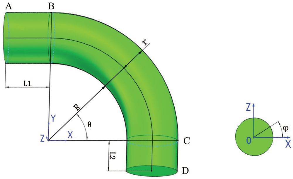
Figure 1: Schematic diagram of the composite elbow
2.2 Schematic Diagram and Working Principle of Composite Elbow Winding Machine
A schematic diagram of the composite elbow winding machine is presented in Fig. 2. The machine consists of an elbow mandrel bracket (1), elbow mandrel (2), carriage assembly (3), servo motor for swinging the carriage (4), servo motor for generating vertical movement of the elbow mandrel (5), counterweight to the elbow mandrel (6), servo motor for rotating the elbow mandrel (7), and machine bed (8). The winding process of the composite elbow can be described as follows. When the cylindrical sections AB and CD are wound, the elbow mandrel is driven by the servo motor (5) to produce vertical linear movement along the machine bed (8), and the carriage assembly (3) is driven by the servo motor (4) and rotates around the elbow mandrel to complete the helical winding process of the cylindrical section. For winding the torus section BC, the composite elbow mandrel (2) is driven by the servo motor (7) and swings around center O while the carriage assembly (3), driven by the servo motor (4), rotates around the elbow mandrel (2) to complete the winding process of the torus section.
Traditional composite elbow winding mandrels usually have cylindrical sections (AB and CD) of equal length on both ends. The length of the cylindrical sections should not be too long, so that the elbow mandrel can rotate about its centerline at both ends, controlled by either a 4-or 5-axis computer-controlled winding machine. However, the 3-axis composite elbow winding machine does not have any cylindrical length requirements on either end of the elbow mandrel and the winding process can be completed by a 3-axis CNC winding machine, which reduces the cost and is more efficient. In this kind of winding machine, when swing radius R of the torus changes, the distance between the carriage assembly and the bed can be adjusted by the screw adjustment mechanism to ensure the geometric center O’ of the composite elbow coincides with the rotation center of the carriage assembly. The elbow mandrel is arranged vertically to ensure the carriage assembly rotates on the horizontal plane. This makes it easy to place the winding fiber tows and deal with problems in the winding process, however, it is also easy to collect excess resin during the winding process. Therefore, a counterweight weight must be added to counteract the weight of the elbow mandrel, which presents a disadvantage.
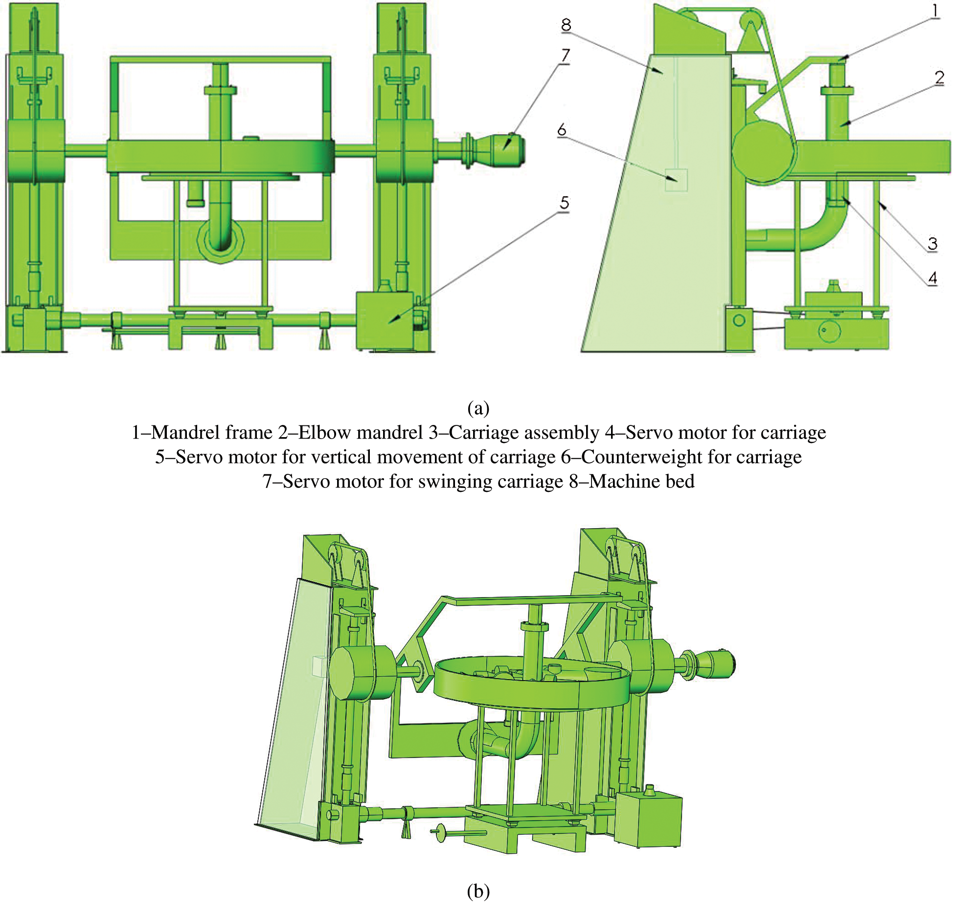
Figure 2: Schematic diagram of winding machine for composite elbow
3 Design of Fiber Winding Trajectory on Composite Elbow
3.1 Fiber Trajectory Equation for Torus Section
Generally, the elbow can be regarded as a part of the torus. In elbow section BC, shown in Fig. 1, the corresponding parameter expression of the torus r (φ, θ) is [11]
where R is the bending radius of the torus; r is the radius of the torus; and φ and θ denote the angular coordinates along the meridional and parallel direction of the torus, respectively, φ ∈ (0, 2π), θ ∈ (0, π/2).
Considering a microelement on the torus of the elbow section, as shown in Fig. 3, we obtain.
where α is the winding angle.
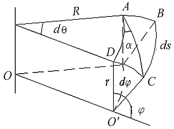
Figure 3: Microelement on the torus section of the elbow
According to differential geometry [12], the geodesic curvature of the torus kg is
When kg is zero, from Eq. (4), the geodesic equation of the torus is
From Eqs. (2), (3), and (5), the geometric relationships dθ/dφ and dα/dφ can be defined as follows:
Then, integrating Eq. (6) yields the geodesic equation of the torus:
If we set the ratio of bending radius and elbow radius as n = R/r, Eq. (8) can be reduced to
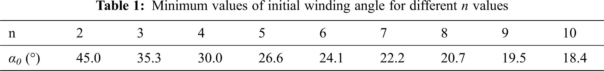
From Eq. (9), it can be seen that the geodesic equation on the torus is only related to the ratio of bending radius and torus radius n and independent of elbow size. If the initial winding angle α0 is defined as the winding angle at the minimum bending radius R − r (φ = 180°) of the torus, αm is the winding angle at the maximum bending radius R + r (φ = 0°) of the torus. In a circle of the torus, the change in winding angle is α0 → αm → α0 and the winding trajectory on the torus is periodically and repeatedly extended. Fig. 4 shows the process of modifying the winding angle based on different n values in a cycle.
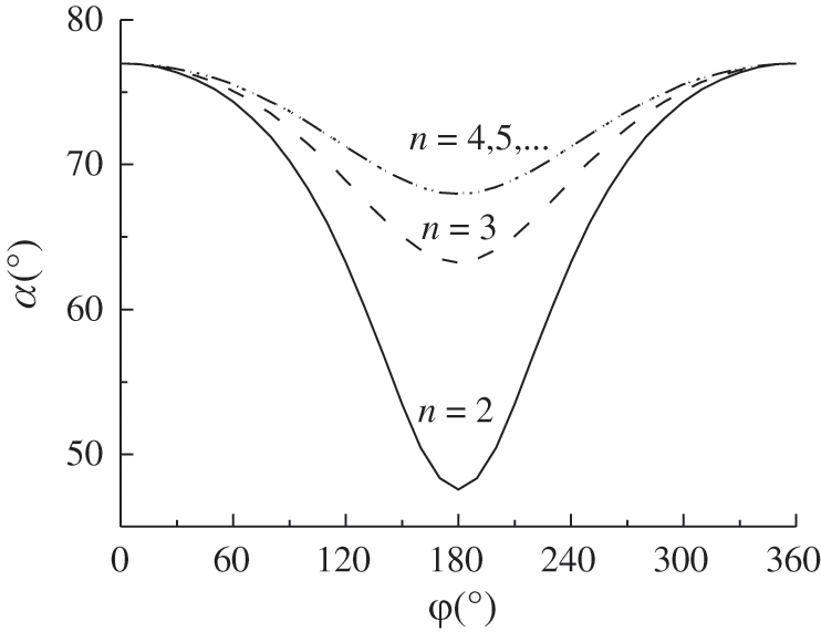
Figure 4: Variation of winding angle in a circle
For special curved surfaces, like the torus, not all geodesic winding can cover the entire surface. To avoid bridging and slippage, the initial winding angle α0 should satisfy the following equation:
Substituting n = R/r into Eq. (10), we obtain
From Eq. (11), variation of the minimum initial winding angle α0 with n in the torus section of the composite elbow is shown in Tab. 1.
According to Eq. (9), the geometric parameter n of the composite elbow and the initial winding angle α0 can be obtained as
In the composite elbow winding machine shown in Fig. 2, when the torus section is wound, the elbow mandrel swings around its center of curvature O and the winding eye continuously rotates on the winding plane of the carriage assembly. Since the swing trajectory of the elbow mandrel around the center of curvature O is exactly same for the torus forming process, a circle can be obtained by truncating the torus through the winding plane of the center of curvature O and its center O’ coincides with the center of the circle formed by the rotation of the winding eye. The combination of the swinging elbow mandrel and rotating winding eye can be used to complete the filament winding process of the torus section. In the winding process, letting(n − 1)cos α0 = a (a constant) and substituting this into Eq. (7), the fiber trajectory motion equation of the torus section can be obtained as
In the winding process of the torus section, the geometric relationship between the rotation angle φ of the winding eye corresponding to different n values and swing angle θ is shown in Fig. 5.
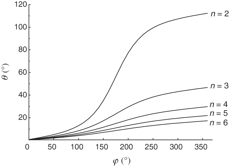
Figure 5: Geometric relationship between φ and θ
3.2 Fiber Trajectory Equation for Cylindrical Sections
As shown in Fig. 1, cylindrical sections AB and CD are located at opposite ends of the elbow mandrel. According to the basic principle of filament winding, the winding angle should reach exactly 90° when passing the open cylindrical ends of the elbow. This means that non-geodesic trajectories should be used for the cylindrical end sections [13]. Thus, the fiber trajectory equations can be expressed as [14]
where Δy is the displacement along the axial line of the cylindrical sections AB and CD,
r is the radius of AB and CD,
Δ
3.3 Filament Winding Pattern Optimization Algorithm
From Fig. 5, we can see that swing angle θ of the elbow mandrel basically changes in line with changes in the rotation angle φ of the winding eye as the ratio of bending radius to torus radius n increases. Integrating Eq. (13) across one circle of the torus, we obtain the swing angle θcircle of the elbow mandrel for one circle of rotation angle φ of the winding eye, as follows:
For the elbow shown in Fig. 2, swing angle θ of the elbow mandrel is 90 degree. When the elbow mandrel swings 90 degree, the total rotation angle φBC of the elbow mandrel can be given by
From the differential terms
The optimized winding angle α’ can be given by
The optimized winding angle α’ can be used as the initial winding angle for cylindrical sections AB and CD, which can each be divided into two sections: a helical section and a transition section. From Eq. (13), the lengths of the transition sections of cylindrical sections AB and CD, denoted L1T and L2T, can be defined as
The helical section lengths of cylindrical sections AB and CD, denoted L1H and L2H, can be given as
From Eq. (15), the rotation angle of the winding eye in the transition sections of cylindrical sections AB and CD, denoted
The rotation angles of the winding eye in the helical sections of cylindrical sections AB and CD are denoted
The total rotation angle
For asymmetric complex parts such as composite elbows, use of the multiple tangent point method for filament winding will lead to fiber bridging on both dome ends. Therefore, the single tangent winding method is usually adopted. If the initial winding angle α0 is given in a winding loop, the sum of the winding eye rotation angle in the torus section and the cylindrical sections are decided. As long as the dwell angle θS in the cylindrical sections is appropriately adjusted on both ends, the total rotation angle of the winding eye in a loop will be an integer multiple of 360° to obtain the single-tangent point winding process. The solution of
The composite elbow is an asymmetric component and the winding angle is a function of the rotation angle of the winding eye. Among the latitude lines corresponding to the surface of the torus,
The projection of a fiber band of width w onto the outer arc is w∕sinαm. The number of fiber bands Np required to cover the outer arc is
To obtain a fiber band offset, the rotation angle increment
4 Control of Filament Winding Motion
4.1 Motion Control System Design
With continuous advances in materials science, computer technology, modern control technology, artificial intelligence, and other related technologies, the traditional manufacturing industry is constantly evolving towards intelligent manufacturing. In recent years, due to continuous progress and improvements in motion control technology, motion control systems have become a mature technology and occupy an important position in the automation industry as independent industrial automation control products. Applications include decision-making in production processes, integrated manufacturing, friendly human-machine, and energy-saving and environmentally friendly processing. Indeed, intelligent manufacturing has become an important trend in factory automation, in which motion control technology also plays a major role, and will beat the core of advanced intelligent manufacturing in the future [15–20].
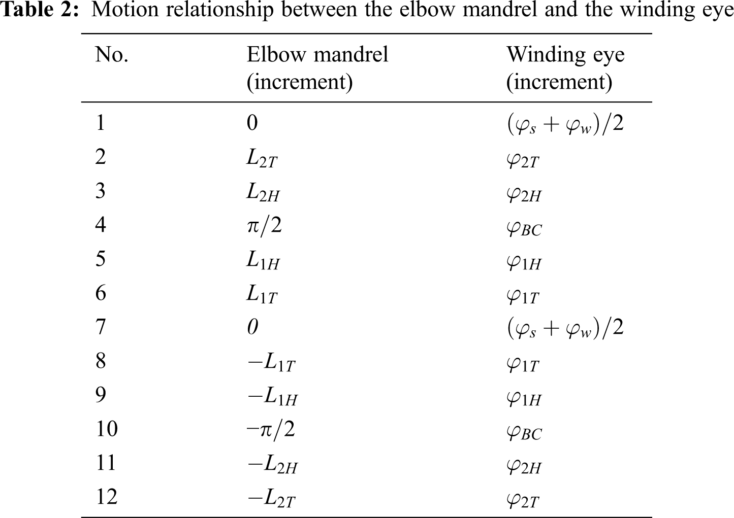
The filament winding machine proposed in this paper is a low-cost system with only three motion control axes, including swing motion of the elbow mandrel, linear motion of the elbow mandrel, and rotation of the mandrel. Three Panasonic servo motors of the A5 series ere used to produce the swing and linear movements of the elbow mandrel and rotation of the winding eye. To control the 3-axis motion of the machinein space, a PMAC-PC104 motion control card (fifth-generation, Delta Tau, USA) was selected. The motion control card uses advanced digital signal processing (DSP) technology, including Motorola 56K series, which is the most powerful motion controller in the world and an outstanding representation of current open CNC system controllers. The fast and accurate calculation ability is transformed into high-precision and fast motion trajectory calculation and control, which can be transformed into precise multi-axis motion trajectories via simple motion programs. The high performance, flexibility, ease of use, and low cost of the controller provide a complete technical solution for realizing the winding patterns of elbows. Once the 3-axis coordinate information is defined, the absolute coordinate mode or relative coordinate mode can be selected. In this study, the relative coordinate mode was used. To cover the surface of the composite elbow, Np loops were required. The relationship between the motion of the elbow mandrel and the winding eye for the three motion axes of the PMAC-PC104 motion control card in each loopare shown in Tab. 2.
Based on the previous winding motion trajectory analysis, Advantech’s industrial control computer, PMAC motion control card and VC++ language were used to design a CAM system for composite elbow filament winding. The control system only requires knowing the length of cylindrical sections AB and CD, ratio n of bending radius R and radius r of the torus, initial winding angle α0, fiber band width w, as inputs to wind the composite elbow.
Take the winding process of the composite elbow as an example, the length of cylindrical sections AB and CD were 400 mm and 150 mm, respectively, the ratio n was 10, the radius of the torus r was 22 mm, the initial winding angle α0 was 51°, the fiber band width w was 5 mm, and the number of tangent points was 1. The steps of the filament-winding process for the elbow are as follows: (1) Enter the parameters in the parameter dialog box; (2) Calculate the stable fiber path to evenly cover the surface of the composite elbow; (3) Generate a control data file based on the 3-axis filament winding machine and download the file to the programmable multi-axis controller (PMAC) board program storage area; (4) Start the winding process of the composite elbow. The composite elbow filament winding pattern is shown in Fig. 6.
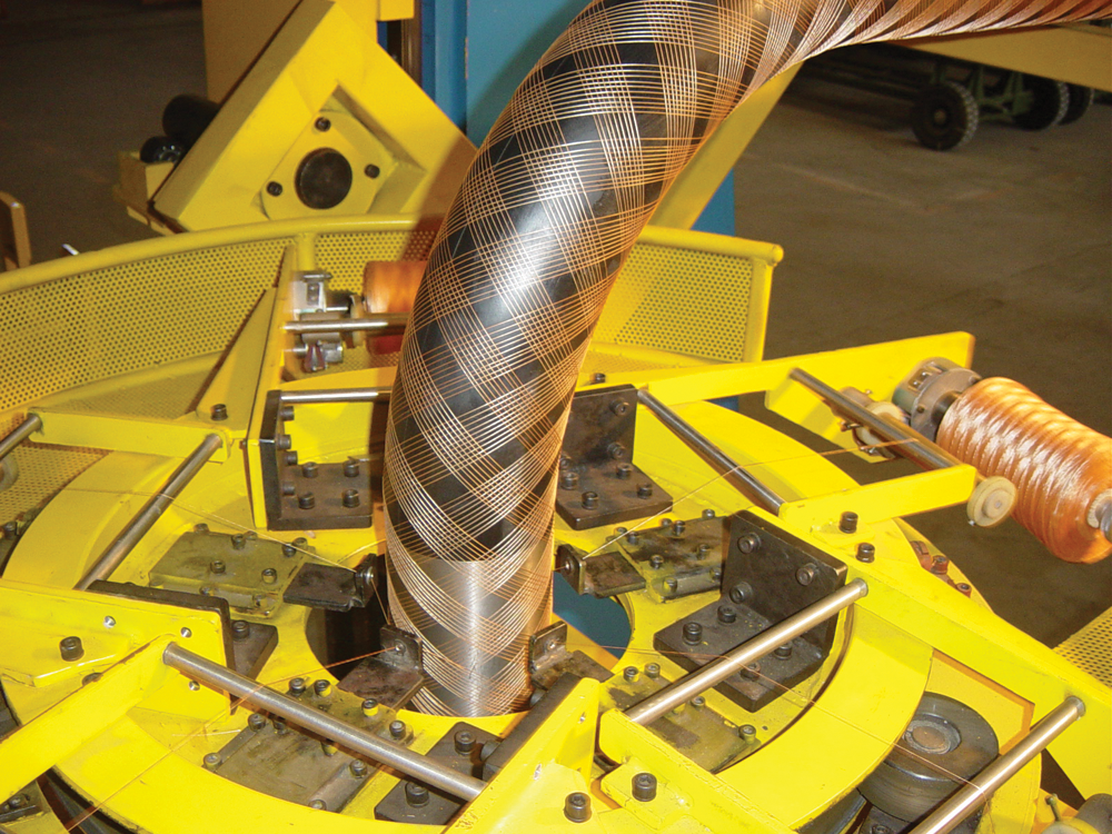
Figure 6: Composite elbow winding pattern used in 3-axis winding machine experiment
1. Fiber winding trajectory equations for the cylindrical sections and torus section of the elbow based on non-geodesic and geodesic winding, respectively, were introduced. In addition, boundary conditions of the initial winding angle without bridging or slippage were proposed.
2. The optimal winding angle α’ can be obtained using the fiber winding trajectory equation of the torus section of the elbow. The motion correspondence relationship in the helical and transition sections of cylindrical sections AB and CD and in the torus section of the elbow were obtained.
3. The motion program was written onto a PMAC-PC104 motion control card and tested on a 3-axis computer-controlled filament winding machine. The results show that the winding pattern is uniform and the motion control process is stable. This not only verifies the correctness of the theory presented in this paper but also shows that the 3-axis computer controlled winding machine can be used for winding of composite elbows. Moreover, the method can be used for winding composite elbows with cylindrical ends of unequal lengths and provides a low-cost approach to composite elbow winding.
Acknowledgement: The authors gratefully acknowledge financial support from the Basic Scientific Research Project (2572020DF01) of Northeast Forestry University and the Fundamental Research Funds for Higher Education Institutions of Heilongjiang Province (grant numbers 135309513 and 135309109).
Funding Statement: This work was supported by a Basic Scientific Research Project (2572020DF01) of Northeast Forestry University and the Fundamental Research Funds for Higher Education Institutions of Heilongjiang Province (grant numbers 135309513 and 135309109).
Conflicts of Interest: The authors declare that they have no conflicts of interest to report regarding the present study.
1. A. Schulze, C. Dahnke and A. E. Tekkaya, “Developments in composite extrusion of complex profiles for automotive applications,” Materials Today: Proceedings, vol. 10, pp. 217–225, 2019. [Google Scholar]
2. V. Mirjalili, R. Ramachandramoorthy and P. Hubert, “Enhancement of fracture toughness of carbon fiber laminated composites using multi wall carbon nanotubes,” Carbon, vol. 79, pp. 413–423, 2014. [Google Scholar]
3. T. Ishikawa, “Overview of trends in advanced composite research and applications in Japan,” Advanced Composite Materials, vol. 15, no. 1, pp. 3–37, 2006. [Google Scholar]
4. C. Chang, Z. Han, X. Li and S. Sun, “A non-geodesic trajectory design method and its post-processing for robotic filament winding of composite tee pipes,” Materials, vol. 14, no. 4, pp. 847, 2021. [Google Scholar]
5. C. Laval, “CADWIND 2006-20 years of filament winding experience,” Reinforced Plastics, vol. 50, no. 2, pp. 34–37, 2006. [Google Scholar]
6. R. Stewart, “Filament winding spins light, strong composite structures with precision,” Reinforced Plastics, vol. 53, no. 3, pp. 34–39, 2009. [Google Scholar]
7. H. S. Li, Y. D. Liang and H. J. Bao, “CAM system for filament winding on elbows,” Journal of Materials Processing Technology, vol. 161, no. 3, pp. 491–496, 2005. [Google Scholar]
8. Z. Lei, X. Hui, H. B. Wang, B. Zhang and B. Zi, “Design and Analysis of Filament-wound Composite Pressure Vessels Based on Non-geodesic Winding,” Composite Structures, vol. 207, pp. 41–52, 2019. [Google Scholar]
9. H. S. Li, Y. D. Liang and H. J. Bao, “CAM system for filament winding on elbows,” Journal of Materials Processing Technology, vol. 161, no. 3, pp. 491–496, 2005. [Google Scholar]
10. J. Z. Xu, Y. Hai, M. J. Liu, J. D. Tian and B. Q. Liu, “Research on winding trajectory planning for elbow pipe based on industrial robot,” International Journal of Advanced Manufacturing Technology, vol. 93, no. 1–4, pp. 34–39, 2017. [Google Scholar]
11. L. Zu, W. D. Zhu, H. Y. Dong and Y. L. Ke, “Application of variable slippage coefficients to the design of filament wound toroidal pressure vessels,” Composite Structures, vol. 172, pp. 339–344, 2017. [Google Scholar]
12. V. A. Toponogov and V. Y. Rovenski, “Modern differential geometry of curves and surfaces,” in Birkhäuser Boston. USA: CRC Press, 2006. [Google Scholar]
13. B. Zhang, H. Xu, L. Zu, D. Li and B. Zhang, “Design of filament-wound composite elbows based on non-geodesic trajectories,” Composite Structures, vol. 189, pp. 635–640, 2018. [Google Scholar]
14. C. Colombo and L. Vergani, “Optimization of filament winding parameters for the design of a composite pipe,” Composites Part B: Engineering, vol. 148, pp. 207–216, 2018. [Google Scholar]
15. B. Mohammed and D. Naouel, “An efficient greedy traffic aware routing scheme for internet of vehicles,” Computers Materials & Continua, vol. 60, no. 3, pp. 959–972, 2019. [Google Scholar]
16. D. Kim and S. Kim, “Network-aided intelligent traffic steering in 5g mobile networks,” Computers Materials & Continua, vol. 65, no. 1, pp. 243–261, 2020. [Google Scholar]
17. I. You, C. Choi, V. Sharma, I. Woungang and B. K. Bhargava, “Advances in security and privacy technologies for forthcoming smart systems, services, computing, and networks,” Intelligent Automation & Soft Computing, vol. 25, no. 1, pp. 117–119, 2019. [Google Scholar]
18. S. K. Kim, M. Köppen, A. K. Bashir and Y. Jin, “Advanced ICT and IOT technologies for the fourth industrial revolution,” Intelligent Automation & Soft Computing, vol. 26, no. 1, pp. 83–85, 2020. [Google Scholar]
19. M. Becherer, M. Zipperle and A. Karduck, “Intelligent choice of machine learning methods for predictive maintenance of intelligent machines,” Computer Systems Science and Engineering, vol. 35, no. 2, pp. 81–89, 2020. [Google Scholar]
20. Z. Xu and Q. Zhou, “Industrial informatics-based applications and techniques in intelligent automation,” Intelligent Automation & Soft Computing, vol. 26, no. 5, pp. 1005–1006, 2020. [Google Scholar]
 | This work is licensed under a Creative Commons Attribution 4.0 International License, which permits unrestricted use, distribution, and reproduction in any medium, provided the original work is properly cited. |