DOI:10.32604/iasc.2021.019730
| Intelligent Automation & Soft Computing DOI:10.32604/iasc.2021.019730 | |
| Article |
The Data Acquisition and Control System Based on IoT-CAN Bus
1College of Information Technology, Jilin Agricultural University, Changchun, 130118, China
2Jilin Province Agricultural Internet of Things Technology Collaborative Innovation Center, Changchun, 130118, China
3Jilin Province Intelligent Environmental Engineering Research Center, Changchun, 130118, China
4Jilin Province Colleges and Universities the 13th Five-Year Engineering Research Center, Changchun, 130118, China
5Department of Agricultural Economics and Animal Production, University of Limpopo, Private Bag X 1106, Sovenga, 0727, Polokwane, South Africa
*Corresponding Author: Ye Mu. Email: MuYe@jlau.edu.cn
Received: 23 April 2021; Accepted: 07 July 2021
Abstract: Presently, the adoption of Internet of things(IOT)-related technologies in the Smart Farming domain is rapidly emerging. The increasing number of sensors used in diverse applications has provided a massive number of continuous, unbounded, rapid data and requires the management of distinct protocols, interfaces and intermittent connections. A low-cost, low-power, and low data-rate solution is proposed to fulfill the requirements of information monitoring for actual large-scale agricultural farms, which we will need pressingly in the future. This paper designs a heterogeneous data acquisition and control system for differentiated agricultural information monitoring terminal. Based on the IoT-CAN bus architecture, the system can adapt different sensors and actuators, realize information exchange, and facilitate modular splicing deployment. At the same time, the heterogeneous network data interface is standardized, and the analytical storage of heterogeneous data is standardized. Lastly, it verifies that IoT-CAN protocol architecture is better than RoboCAN and CANOpen, and systems in agricultural environment. It solves the problems of hardware difference and heterogeneous data in monitoring system, which is of great significance to the establishment of heterogeneous data standard of agricultural information.
Keywords: Agricultural internet of things; IoT-CAN protocol; heterogeneous data; distributed architecture; data analysis
In recent years, the framework of agricultural information system has been initially shaped [1–3]. With the development of intelligent agriculture, different types of sensor equipment from different manufacturers will be used for different crop physiological environment monitoring information. The framework of the agricultural information system has been initially shaped. With the development of intelligent agriculture, different types of sensor equipment from different manufacturers will be used for different crop physiological environment monitoring information.However, there is no uniform standard for the diversity of communication protocols and the application layer protocols of the Internet of things, which leads to the diversity of the underlying devices and gateways of the Internet of things.It has caused the following problems:First, most of the existing Internet of things systems through a single micro-control unit (Microcontroller Unit, MCU) [4] to complete all the tasks of the system. If the task is too complex, it will affect the execution of other tasks, resulting in an inefficient system; Second, the Internet of things gateway is limited by the expansion of the interface of the underlying access device and the limited number of interfaces, so the Internet of things devices with different protocols can only access the gateway supporting the protocol.Thirdly, most of the hardware systems developed by single CPU structure control have strong pertinence and poor expansibility. If the application environment changes or requires access to new hardware, you need to redesign the hardware and update the software.At the same time, most of the Internet of things terminal equipment integration is high, when one of the modules is damaged, it is necessary to take out the whole module for maintenance or replacement, resulting in high maintenance costs. Fourth, because of the heterogeneity of the acquisition terminal, the monitoring data format will be very different, and then a large number of agricultural heterogeneous data will be generated [5,6]. When these heterogeneous data are uploaded to the server and these heterogeneous data are uploaded to the server, one is to increase the complexity of processing data, the other is because the data parsing methods used in agricultural factories or data centers are different. We can't directly use existing data resources, which will cause waste of information resources. When processing, one is to increase the complexity of processing data, the other is because of the different data analysis methods used in agricultural factories or data centers.
In the field of industry, modular design has some research results [7]. Christian et al. [8] proposed a modular, distributed and extensible spacecraft system architecture, which is consistent in the design of basic modules, improves the potential of saving, and increases the versatility of hardware. J. Su proposed Idle slots skipped mechanism based tag identification algorithm with enhanced collision detection [9] and a way that redundant rule detection for software-defined networking [10]. Park [11] proposed a communication technology means using the remote engineering unit (REUs), that is, to realize the autonomous work and communication of the remote engineering control unit through the I2C bus [12]. To meet the requirements of flexibility and reconfiguration, distributed architecture also needs to develop component distributed design patterns on software. For example, RoboCAN (Robot CAN bus) [13] is a distributed hardware design by deploying software engineering on a single chip microcomputer [14,15]. CAN bus has been successfully applied to many key control systems. By developing the new module and improving the design and optimization of the control algorithm, a modular architecture can be created for the integration of sensor data and distributed hardware control in the field of agricultural Internet of things, and the control architecture can be upgraded.
With the upgrading of the agricultural Internet of things industry, it is necessary to upgrade the existing monitoring information collection system architecture and establish an efficient information collection and control system [16], so that it can break through the limitations of the existing collection links processing heterogeneous data. Maximize the integration and utilization of existing information resources.Therefore, this paper designs an agricultural heterogeneous data acquisition and control system based on IoT-CAN bus architecture protocol by combining IoT-CAN (Internet of things CAN, the following IoT-CAN) field bus [17,18], and stm32 lightweight programming.
Based on the existing Internet of things model [19], which includes three layers: perception layer, network layer and application layer, this paper proposes an agricultural heterogeneous data acquisition and control system based on IoT-CAN bus.On the IoT-CAN architecture in the perception layer, hardware units such as sensors, actuators, and communication modules are integrated to maximize the scalability of monitoring terminal design. IoT-CAN system consists of three parts: monitoring terminal, network data interface in transmission layer and network platform in application layer. Based on the modular minimum unit control design of CAN bus, the monitoring terminal realizes the collection of sensor information in various agricultural facilities and the preliminary processing of heterogeneous data standardization. The network data interface consists of two parts: data communication and data processing. The former transmits the information collected by the information monitoring terminal to the remote data server, and the latter receives the transmitted data.According to the predefined unified data format, the data is standardized and stored, which is convenient for the network platform in the system. According to the requirement of parameter control, the network platform can display the agricultural information data and complete the remote network monitoring of agricultural information. At the same time, according to the requirement of parameter control, the control instruction is conveyed down through the network data interface, and the actuator on the CAN-IoT bus wakes up and receives the execution.
3 IoT-CAN Hardware Modular Design
3.1 IoT-CAN Modular Architecture
IoT-CAN architecture design takes “high aggregation, low coupling” as the design principle in software engineering. By CAN bus communication, each module is divided according to the task, which reduces the coupling of the module. By combining different modules, the roles of acquisition node, control node and gateway node can be transformed. As shown in Fig. 1 above, the perception layer is a schematic diagram of the modular architecture, in which various modules and their functions are: (1) Data Acquisition Module (DAM): sensors that are responsible for data acquisition and support mainstream interface protocols; (2) Device Control Module (DCM): Responsible for device control and can control devices using mainstream interface protocols; (3) Power Clock Module (PCM): Responsible for system power supply and system clock; (4) Data Storage Module (DSM): responsible for bus data storage. (5) Human Interaction Module (HIM): responsible for human-computer interaction, support LCD display information, voice broadcast, key input, etc.; (6) Edge Calculation Module (ECM): responsible for edge computing [20,21], For example, by using the single-chip module to analyze the collected data for basic automatic control, etc., the burden of the cloud server is reduced. (7) Data Transmission Module (DTM): Responsible for data transmission, supports mainstream communication methods such as ZigBee, WiFi , 4G, NB-IoT, and can be connected to other cloud platforms through configuration.
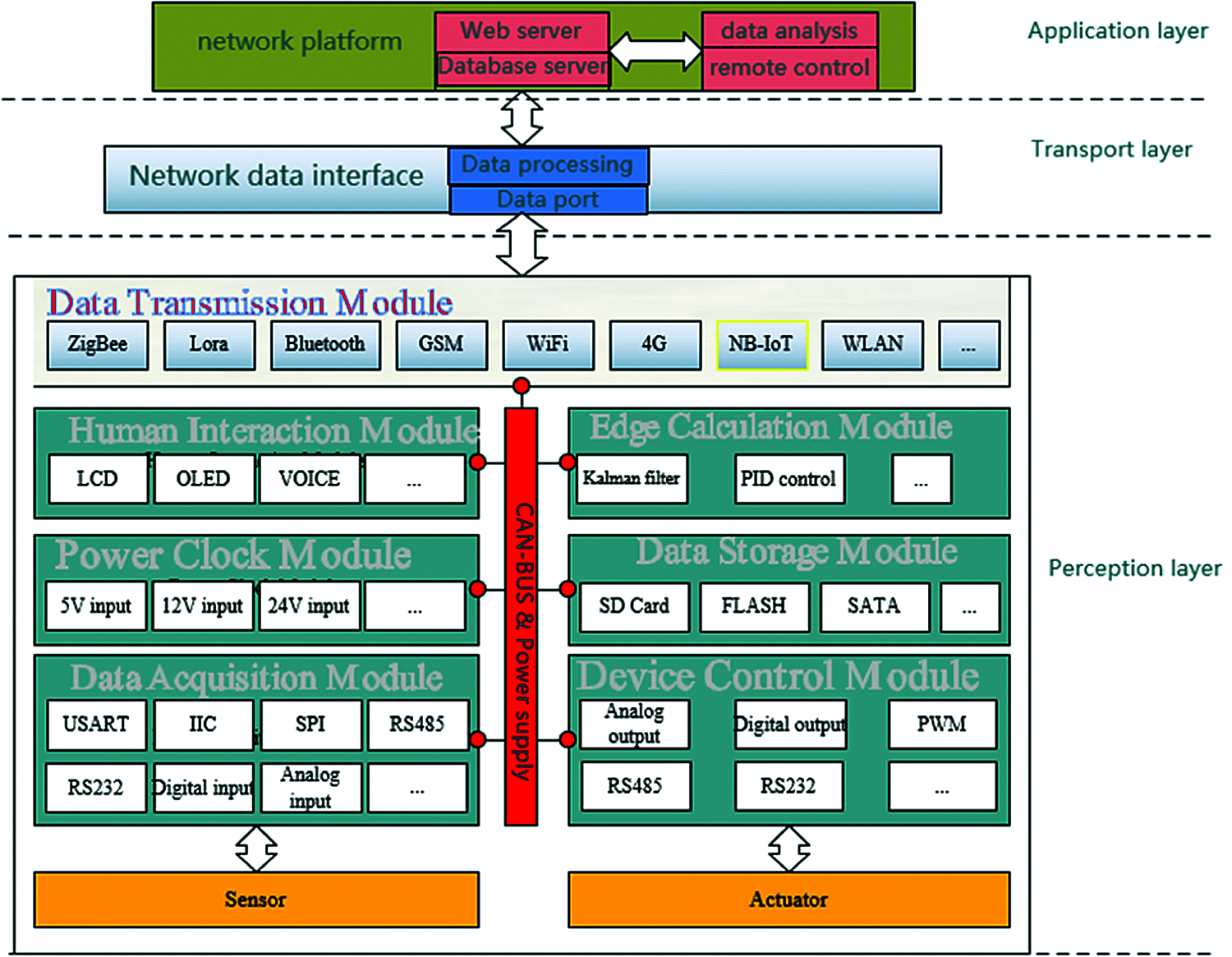
Figure 1: System architecture of heterogeneous data monitoring platform based on IoT-CAN
In Task Communication, ITC, each module performs its task, similar to the Embedded Operation System, RTOS operating mechanism.Nowadays, due to the limitation of the core number of Micro Controller Unit, MCU, the tasks in most RTOS [22,23] are asynchronous, and only one task is running at each time.But in the agricultural IoT-CAN, because of the multi-work together, each task is synchronized, at the same time, the multi MCU also means more available resources, which can meet some complex functional requirements. Fig. 2 is a structural diagram of the agricultural IoT-CAN device, including the communication layer, interface layer, hardware layer, driver layer, and task layer. The agricultural IoT-CAN protocol is located in the communication layer and the interface layer and is responsible for bus communication.
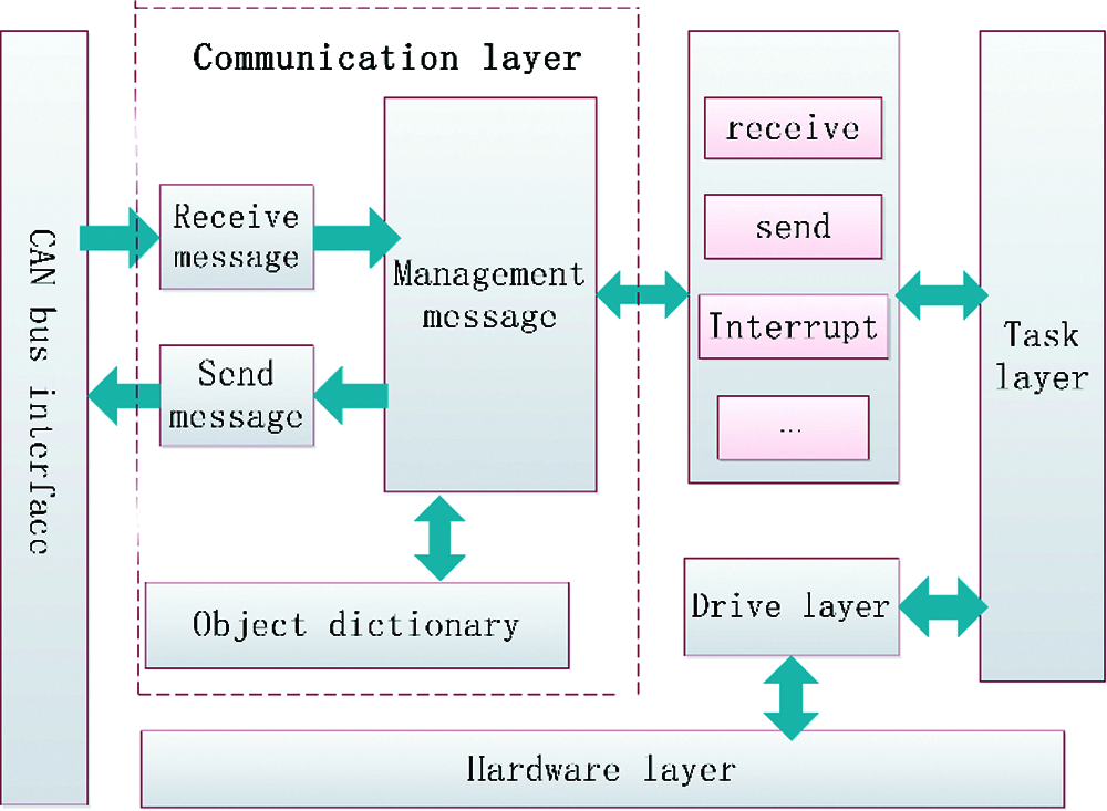
Figure 2: Agricultural IoT-CAN device structure
The IoT-CAN protocol is developed based on the CAN standard. The protocols developed based on this standard include DeviceNet [24] for information exchange, security equipment and large-scale control systems; Smart Distributed System (SDS) for highly trusted smart device-level networks; CAN Kingdom [25] applied to machine systems; CANOpen [26,27] applied to industrial control; RoboCAN applied to robot hardware control and sensor data integration. The agricultural IoT-CAN has the same design goals as RoboCAN. It has a centralized, lightweight, expandable and open system that can quickly integrate sensors, controllers and communication modules on the IoT-CAN bus board. It is used in the fields of facility agriculture, environmental monitoring, industrial manufacturing, etc. Therefore, the protocol needs to meet: (1) Hot plugging of equipment (2) Flexible communication mode (3) Expandable equipment (4) Transparent data transmission (5) Support bus configuration.
IoT-CAN is a non-master-slave protocol that does not require a master-slave protocol to maintain the system, removes the complicated registration mechanism of the master-slave protocol, uses static ID, divides the CAN-ID interval according to the type of module, and supports standard frames and extended frames. Fig. 3 shows the agricultural IoT-CAN ID allocation map. The first 3 digits of the ID are the module code. Each module has a designated module code. The smaller the module code, the higher the communication priority; the middle 5-bit standard frame or 23-bit extended frame It is an object code. Each type of device in the module has a unique object code on the same bus, such as ambient temperature and humidity sensors, CO2 concentration sensors, etc.; The last 3 digits are the node number to ensure that there can be up to 8 devices of the same module and type on the same bus. The node number can be obtained through program definition or external input.
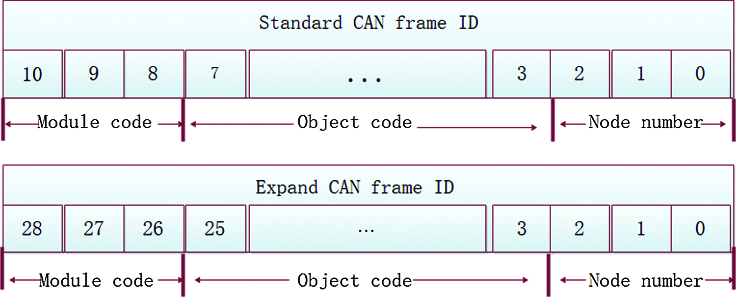
Figure 3: Agricultural IoT-CAN ID allocation diagram
3.3 IoT-CAN Module Design and Data Collection
A development board and expansion module based on IoT-CAN design are shown in Fig. 4: Through the design of serial port download switching circuit, can access the designated module download program, easy to debug between modules. The circuit connection mode is consistent with each expansion module, and the program based on the experimental development board can be downloaded directly to the corresponding module. The Development board leads to the main control of all I/O ports for easy expansion. The design module is divided into three parts: CAN transceiver, MCU, peripheral, CAN transceiver, and MCU as the basic part, and the peripheral is the extended part, depending on the type of module.
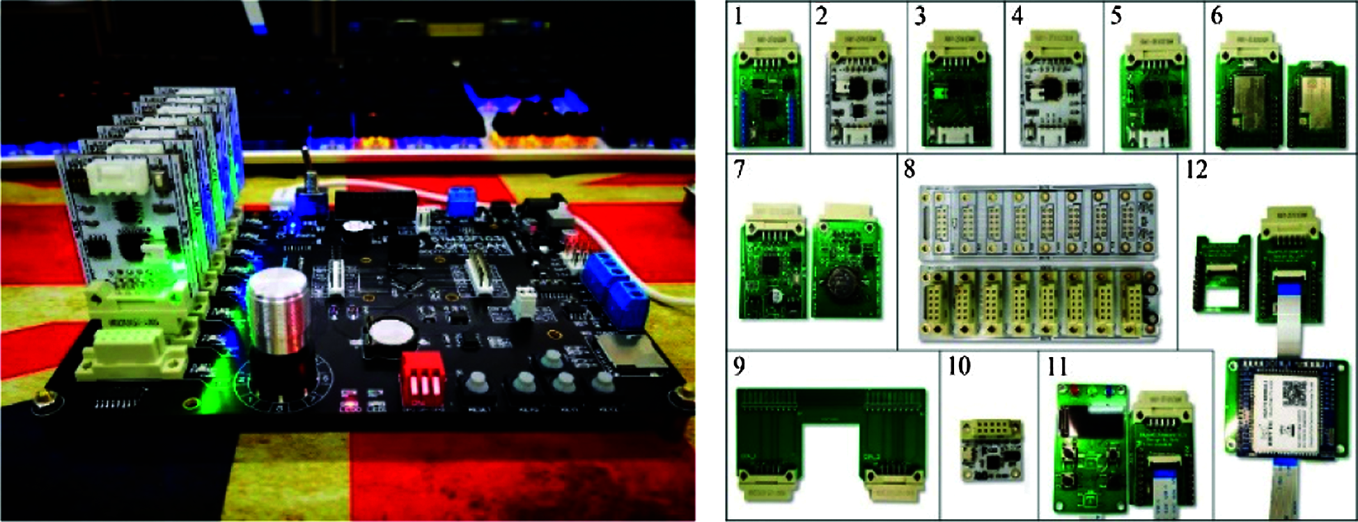
Figure 4: Physical map of the development board and expansion module
The heterogeneous data in agriculture is mainly collected by sensors. Because of the different transmission protocols, the data format frames are different.The common MS10 series of soil sensors, for example, use 485 interface transmission protocols, while the illumination SHT10 series of sensors use I2C interface protocols, and some CO2 sensors use serial ports. These results in the complexity of the hardware interface and the complexity of heterogeneous data analysis.However, the circuit design idea based on CAN bus in this paper provides a unified and universal physical conversion interface and encapsulates each sensor into a minimized module unit for easy splicing.The STM32 added on the module interface unit is used as the control chip MCU, whose function is to drive the sensor to complete the data acquisition function and convert the collected data into a data frame that can be transmitted on the IoT-CAN bus protocol.When all sensors complete the parameter information acquisition, all the information is sent to the IoT-CAN bus, and the data integrity is judged CAN the specific MCU of the bus.If the preset environmental parameters have been collected, all the IoT-CAN generated by a single sensor are encapsulated into a complete standardized data format.Then the complete data frame is transmitted by the data sending module on the IoT-CAN bus, such as the ZigBee module, the LoRa module and so on, so as to facilitate the function of performing data parsing better after the data is uploaded.
4 Network Data Interface Design
The receiving part of the network data interface uses the HP-Socket framework to build.When the server turns on the listening service, it waits for the node to establish a connection; The IoT-CAN monitoring terminal communicates with the network data interface through the TCP/IP protocol, and the server uses a fixed IP address to send the monitoring data to the server port.When there is a connection request, a new thread is created for data processing; After the data verification is passed in the thread, if the data is complete and meets the set requirements, the uploaded standardized data frame will be parsed through the standard data frame, and the corresponding data parsing results will be transmitted to the corresponding data storage server. The data analysis flowchart is shown in Fig. 5 below.
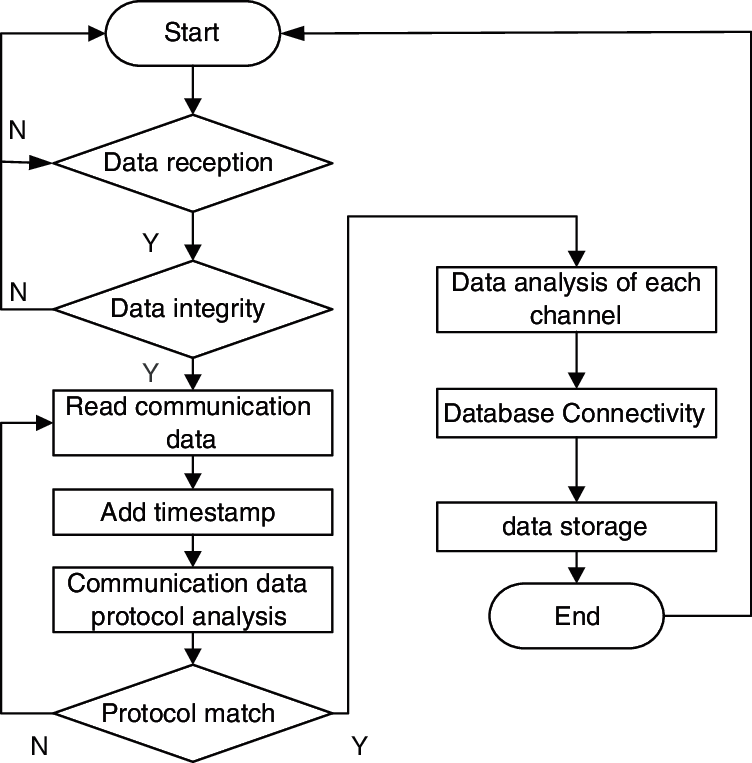
Figure 5: Data analysis flowchart of heterogeneous network
4.2 Data Standardization Analysis Storage
The system uses the HP-Socket framework to build the TCP service in the server. The node connects the service through the TCP protocol to realize the heterogeneous data upload and the control instruction.Based on the TCP protocol, the platform defines the communication data format, including start and stop, item identification number, separator, terminal unique network serial number, parameter packet, check code.Entry and stop character determines whether the data is complete or not; the item identification number identifies the item information, such as the planting item, the breeding item, etc.; the separator separates each part of the data; the terminal uniquely enters the network serial number to identify the node to be subordinate; the parameter data packet carries the node to collect the data or to control the instruction data; the verify the correctness of the data, using the CRC16 check, the following is a complete data packet:
[JLAU0001WS#0000000000000001#20190101120000@LTIT0144.90&EVTP026.10&EVHM064.00#A56A]
The definition of the data format is shown in the following 9 diagrams, where “[ ]” is the start and end character, each occupying 1 byte; “JLAU0001WS” is the project identification number, occupying 8 bytes; “#”, “@”, “&” are Separator, each occupies 1 byte; “0000000000000001” is the unique network access serial number of the terminal, which occupies 16 bytes;
“20190101120000@LTIT0144.90&EVTP026.10&EVHM064.00” is the parameter data packet, and the time and parameters are separated by “@” , Each parameter is separated by “&”, time occupies 14 bytes, and each parameter occupies at least 6 bytes; “LTIT0144.90” is a complete parameter data, the first four bytes are parameter codes, and the fifth byte is Parameter serial number. Each node can carry multiple sensors of the same type. This byte can be used to distinguish between the parameters, and the subsequent bytes are the parameter values; “A56A” is the check code, which occupies 4 bytes.
This system uses MySQL database, and uses the Druid database connection pool to connect to the MySQL database through Java language. After reading the database data, it is parsed and processed by the server and sent to the browser front end for display; at the same time, the browser front end input The control terminal protocol and other contents are sent to the server background and written into the database after the server language analysis.
4.3 Data Communication Control
Network data is responsible for the down transmission of server-side control data instructions. After the application layer in the remote server is judged according to the collected data, the corresponding control instruction is executed, and the network data interface is used to issue the instruction to the executive terminal of the IoT-CAN bus board, so as to complete the control process.
For the sake of network security, the server needs to be isolated from the application program when the server controls the data to be written into the database, so the database cannot directly call the network data interface program, and the network data interface needs to periodically check the MySQL database. When the control command identification is found, the content of the control command is read and transmitted to the monitoring terminal through serial communication and TCP/IP protocol. The specific operation process is shown in Fig. 7.
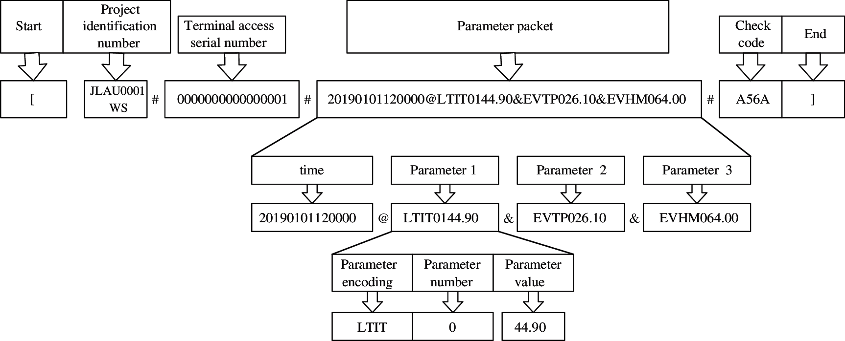
Figure 6: Schematic diagram of data frame analysis
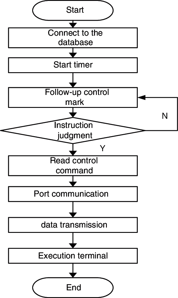
Figure 7: Control command issuance process
5 System Performance Test and Platform Application
5.1 Transmission Performance Test
5.1.1 Analysis of Comprehensive Bandwidth Usage
The usage of communication bandwidth in different cases is used as the reference standard of protocol performance. The bandwidth test uses the design and development board as the protocol performance test platform; the USBCAN-2E-U CAN bus analyzer is used to obtain the bus communication data; the communication uses standard frames with a baud rate of 500 Kbps. The CAN bus analyzer can obtain each frame of bus communication data (including frame ID and frame data, etc.) and the corresponding time, and then calculate the bandwidth usage in units of 1 s. Through Fig. 6, we can clearly see the data frame analysis process.
Fig. 8 shows the bus bandwidth usage when the two data transmission modules perform data transparent transmission. In the data transparent transmission mode, a response is generated for each message, so the effective data transmission rate Vf needs to remove the bandwidth occupied by the protocol. The calculation formula of Vf is as follows:
where V is the total bandwidth usage, Bf is the number of bytes available for one communication, and B is the total number of bytes for one communication. In agricultural IoT-CAN,

Figure 8: Bandwidth usage during data transparent transmission
The data transparent transmission function is used to transmit long strings and large data blocks between the edge computing module, the data transmission module and the data storage module. The real-time communication requirements are lower than other modules. Fig. 9 shows the simultaneous data collection and data transmission. Bandwidth usage at the time. The data transmission module DTM_1 only needs 2 bytes to send a data request, so the occupied bandwidth is the lowest; 4 data acquisition modules (DAM) need 8 bytes to respond to the request, and the occupied bandwidth is basically the same; when the data is transparently transmitted, DTM_2 is the sender to send data. Many, DTM_3 responds to the receiver to send less data, so DTM_2 has a higher bandwidth than DTM_3; it can be seen from the figure data that the data transparent transmission task and the data collection task do not interfere with each other.
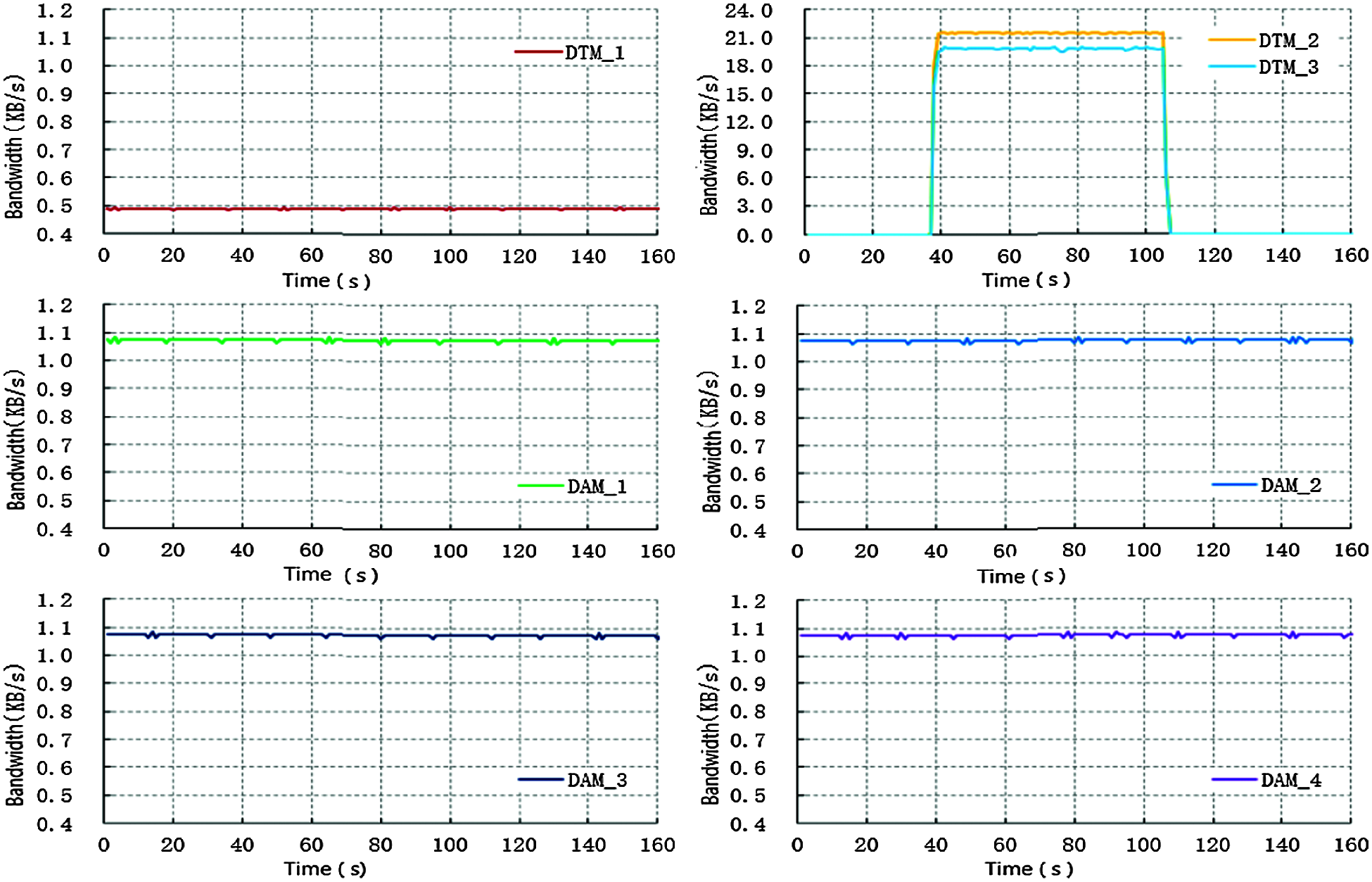
Figure 9: Comprehensive utilization of bandwidth
The above experimental results show that when the protocol transmits data transparently, the bandwidth usage is about 45 KB/s, and the effective data transmission rate is about 12.27 KB/s. It has a faster transmission rate and meets the requirements of the architecture data transparent transmission rate; When data transparent transmission and data collection are performed at the same time, each task can be scheduled according to the bus priority, and tasks with lower priority such as data transparent transmission and higher priority tasks such as data collection do not interfere with each other.
5.1.2 Comparison of Protocol Data Transmission Efficiency
CAN2.0A CAN standard frame has 11 bits of CAN ID. According to different data transmission lengths, the total length of data CAN be between 47 and 111 bits. At the same time, the ratio of transmitted payload and standard frame length, the maximum data transmission efficiency of CANstandard frame CAN be 57.7%. Fig. 10 is a comparison diagram of the transmission efficiency among IOT-CAN, ROBOCAN and CANOPEN. We compared the transmission efficiency among IOT-CAN, ROBOCAN and CANOPEN.It suggests that IOT-CAN is performing the same operation with a higher transmission efficiency, and its maximum data transmission efficiency is about 55.2%. The main reason is that IoT-CAN streamlines the command byte and uses part of the CAN ID as the command identifier. 35/5000 According to the reference, the data transmission efficiency of RoboCan is about 51.9%. The test data of CANopen was obtained through the test environment's built, and the data transmission efficiency of CANopen was about 54.5%.
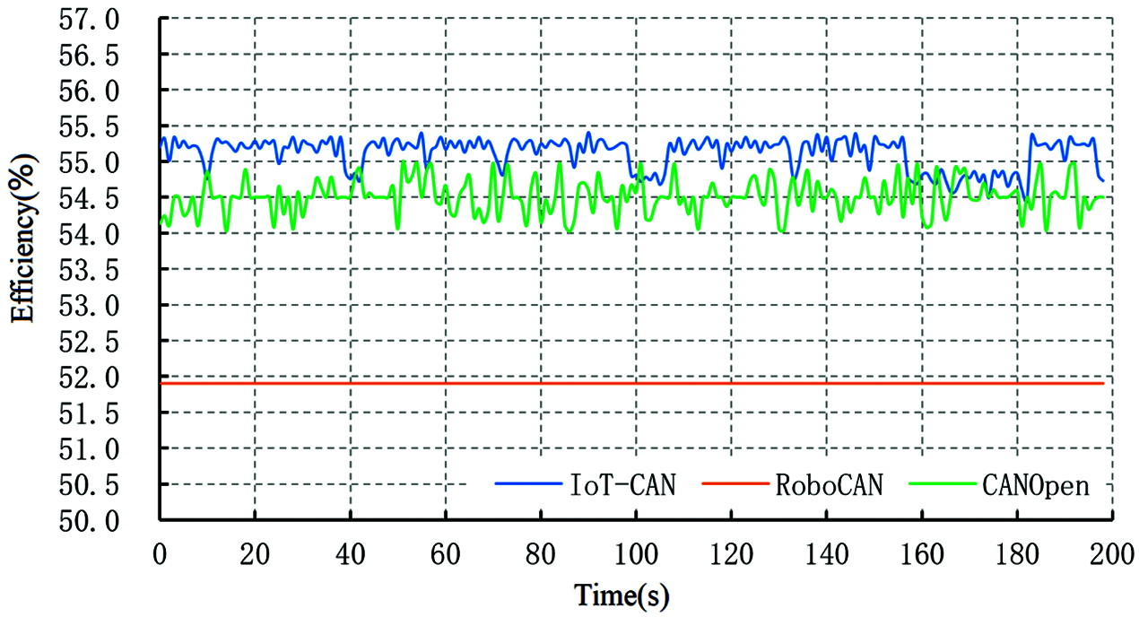
Figure 10: Comparison of transmission efficiency of IoT-CAN, RoboCAN and CANOpen
5.2 Practical Examples of Monitoring Platform
5.2.1 Agricultural Greenhouse Applications
When the sensor module is connected with the transfer module of the IoT-CAN bus designed above, the sensor driver code can be executed in the STM32, and the normal parameter monitoring can be carried out according to the environmental operation requirements of the greenhouse shed. Fig. 11 shows the environmental parameter monitoring node based on module prototype design, which is used for architecture testing and extended module development respectively.
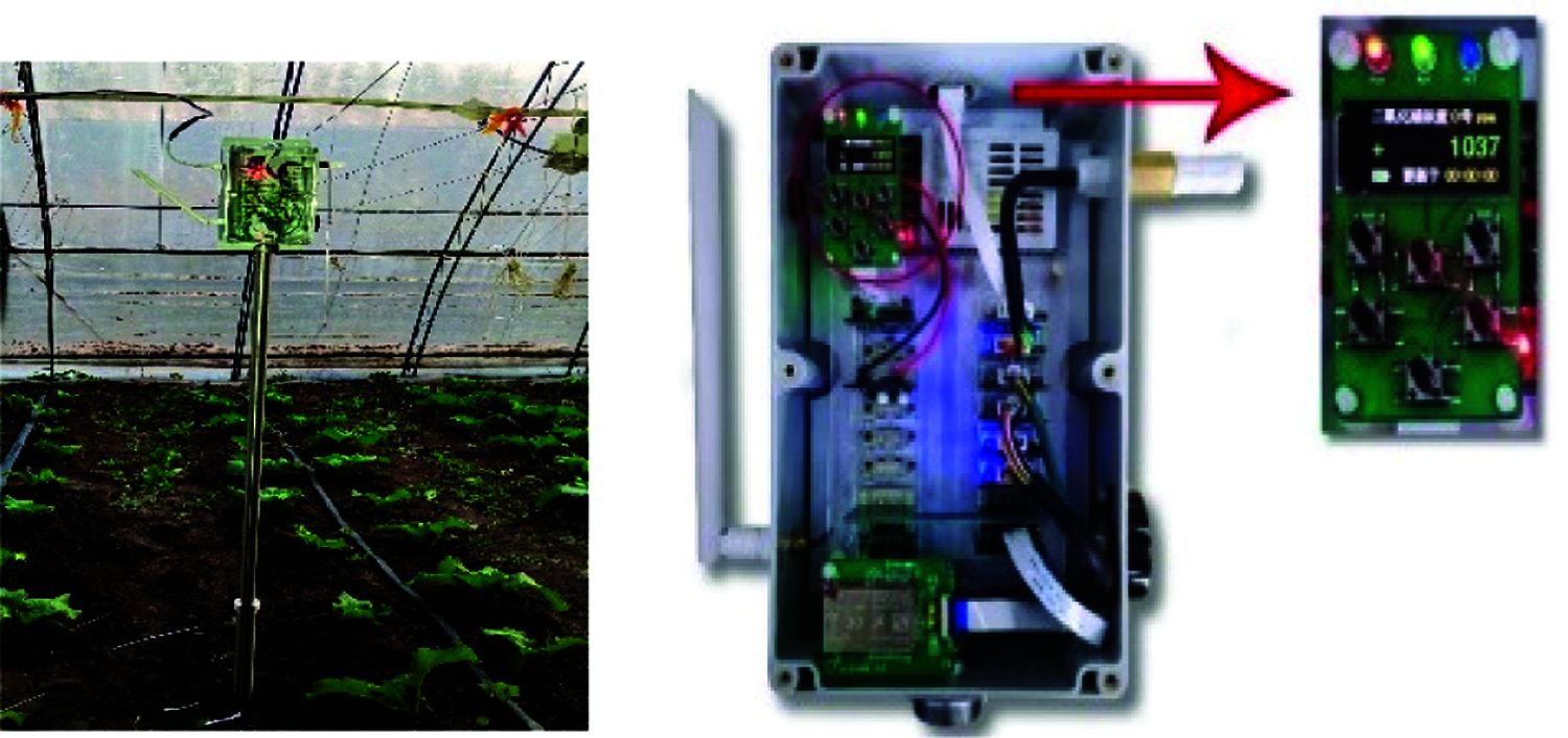
Figure 11: The physical work display of the greenhouse monitoring node
The cloud server provides data receiving and storage service and web page access service, which is used to realize the visual display of the collected data, including the information of collecting location, air temperature and humidity, light intensity, carbon dioxide concentration and so on.The server background is responsible for connection processing output database data and receiving user data for front-end transmission.The function of monitoring platform is divided into three parts: user management, data display and remote control.User management is mainly used for user login verification; data display adopts three forms: broken line diagram, bar chart, and data view, and supports the export of excel data files and collect data.Remote control monitors the acquisition terminal through web page settings. Fig. 12 shows the partial interface of the network platform.
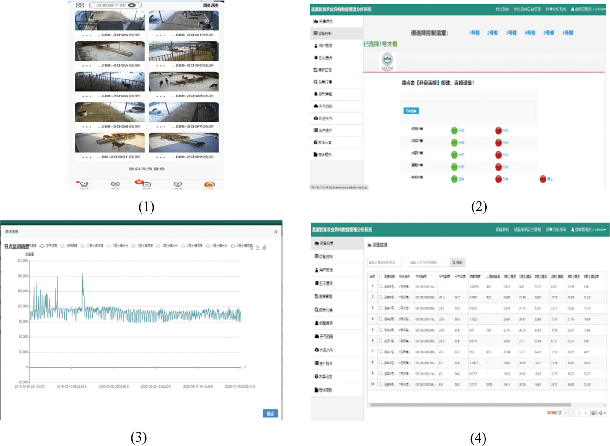
Figure 12: Part of the monitoring platform interface (1) Video Surveillance (2) Remote control interface (3) Monitoring data curve (4) Preview of each monitoring node information
5.2.2 Development of Environmental Monitoring Devices for Deer Farms
The deer farm environmental information monitoring node and equipment control node are also designed based on the bus structure, and each module of the node can be added or deleted according to the actual scene to avoid the repeated design of the circuit.It can be put into use only by modifying the peripheral driver code, saving development time. The usage is shown in Fig. 13 below.
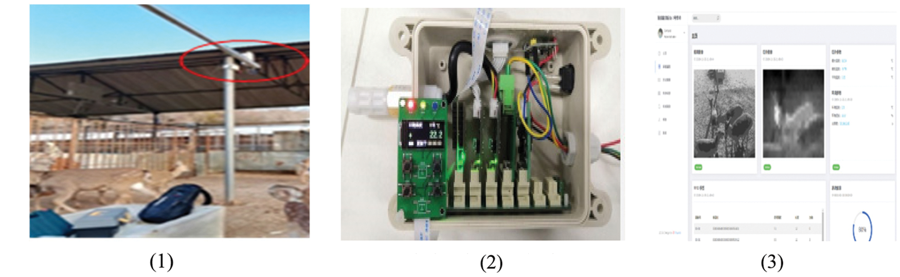
Figure 13: Environmental monitoring design and actual use of the deer farm (1) Installation of monitoring node (2) Node hardware display (3) Platform monitoring
According to the demand of the monitoring system of the agricultural Internet of things for the processing of heterogeneous data, the standardized collection system of agricultural data based on the IoT-CAN bus is designed. After practical verification and use, the following three conclusions are obtained:
1. The hardware architecture of the IoT-CAN bus is highly versatile, combining different sensor modules to meet the needs of different scenarios. Through the basic functional interface provided by the protocol, the fast access of each hardware unit can be realized, and the development cycle can be reduced. It only needs to be modified at the software level based on the developed hardware. The construction of experimental environment and experimental environment and product development.Each module in the architecture is relatively independent, any module damage does not affect the whole system, by replacing the damaged module can eliminate the fault.
2. The performance and practicality of the IoT-CAN bus protocol is strong. Through the test of the protocol performance of the IoT-Can, the results show that the load bandwidth can meet the transmission requirements in the agricultural Internet of Things. At the same time, IoT-CAN is compared with RoboCAN and CANOpen has higher transmission efficiency and is more suitable for modular design applications in the agricultural Internet of Things.
3. The network data interface designed by this system performs unified and standardized data frame analysis and storage for the CAN format data frames uploaded through the IoT-CAN bus module to facilitate the unified call of subsequent data. Through the use in multiple scenarios of the agricultural Internet of Things, such as greenhouse environment monitoring, deer farm environment and deer physical sign monitoring devices, the data collection reliability of heterogeneous data systems based on IoT-CAN bus hardware topology architecture is proved.
Funding Statement: This research was supported by The People's Republic of China Ministry of Science and Technology [2018YFF0213606-03 (Mu Y., Hu T. L., Gong H., Li S. J. and Sun Y. H.) http://www.most.gov.cn], the Science and Technology Department of Jilin Province [20160623016TC, 20170204017NY, 20170204038NY, 20200402006NC (Hu T. L., Gong H. and Li S.J.) http://kjt.jl.gov.cn], and the Science and Technology Bureau of Changchun City [18DY021 (Mu Y., Hu T. L., Gong H., and Sun Y. H.) http://kjj.changchun.gov.cn].
Conflicts of Interest: The authors declare that they have no conflicts of interest to report regarding the present study.
1. M. Ayaz, M. Ammad-Uddin, Z. Sharif, A. Mansour and E. M. Aggoune, “Internet-of-things (IoT)-based smart agriculture: Toward making the fields talk,” IEEE Access, vol. 7, no. 1, pp. 129551–129583, 2019. [Google Scholar]
2. F. Xiang, F. Yan and X. Liu,“Study of wireless communication technologies on internet of things for precision agriculture,” Wireless Personal Communications, vol. 108, no. 3, pp. 1785–1802, 2020. [Google Scholar]
3. J. Y. Zhang, “Research on fault self diagnosis techology of agricultural internet of things information collection system,” in Int. Conf. on Artificial Intelligence and Security, New York, NY, USA, pp. 373–383, 2019. [Google Scholar]
4. T. N. B. Anh and S. Tan, “Real-time operating systems for small microcontrollers,” IEEE Micro, vol. 29, no. 5, pp. 30–45, 2009. [Google Scholar]
5. C. K. Swain, B. Gupta and A. Sahu, “Constraint aware profit maximization scheduling of tasks in heterogeneous datacenters.” Computing, vol. 102, no. 10, pp. 2229–2255, 2020. [Google Scholar]
6. A. Nazábal, “Handling incomplete heterogeneous data using VAEs,” Pattern Recognition, vol. 107, no. 1, pp. 107501, 2020. [Google Scholar]
7. D. Losada, “Distributed and modular CAN-based architecture for hardware control and sensor data integration,” Sensors, vol. 17, no. 5, pp. 1030, 2017. [Google Scholar]
8. S. Wernitznigg, C. Fidi and AT. Loveless, “A modular, scalable avionics architecture for future exploration missions,” in 2018 AIAA SPACE and Astronautics Forum and Exposition, New York, NY, USA, 2018. [Google Scholar]
9. J. Su, R. Xu, S. Yu, B. Wan and J. Wang, “Idle slots skipped mechanism based tag identification algorithm with enhanced detection,” KSII Transactions on Internet and Information Systems, vol. 14, no. 5, pp. 2294–2309, 2020. [Google Scholar]
10. J. Su, R. Xu, S. Yu, B. Wang and J. Wang, “Redundant rule detection for softwaredefined networking,” KSII Transactions on Internet and Information Systems, vol. 14, no. 6, pp. 2735–2751, 2020. [Google Scholar]
11. S. Park, “Distributed architecrure for controlling spacecraft/robotic vehicles using remote engineering unit (REU),” 19th DASC.19th Digital Avionics Systems Conference, vol. 2, no. 8, pp. 8B5/1–8B5/8, 2000. [Google Scholar]
12. S. A. Ebad and M. Ahmed, “Investigating the effect of software packaging on modular structure stability,” Computer Systems Science and Engineering, vol. 34, no. 5, pp. 283–296, 2019. [Google Scholar]
13. L. Joaquin, D. Pérez and E. Zalama, “A framework for building mobile single and multi-robot applications,” Robotics and Autonomous Systems, vol. 59, no. 3, pp. 151–162, 2011. [Google Scholar]
14. Y. Chou, W. Liao, Y. Chen, M. Chang and P. T. Lin, “A distributed heterogeneous inspection system for high performance inline surface defect detection,” Intelligent Automation & Soft Computing, vol. 25, no. 1, pp. 79–90, 2019. [Google Scholar]
15. H. A. Thompsona, H. Benitez-Pereza, D. Leea, D. N. Ramos-Hernandeza, P. J. Fleminga et al., “A CAN bus-based safety-critical distributed aeroengine control systems architecture demonstrator.” Microprocessors and Microsystems, vol. 23, no. 6, pp. 345–355, 1999. [Google Scholar]
16. A. Tzounis, N. Katsoulas, T. Bartzanas and C. Kittas, “Internet of things in agriculture, recent advances and future challenges.” Biosystems Engineering, vol. 164, no. 1, pp. 31–48, 2017. [Google Scholar]
17. T. L. Zhou and J. Zhang. “Design and implementation of agricultural internet of things system based on aliyun IoT platform and STM32,” Journal of Physics: Conference Series, vol. 1574, no. 1, pp. 435–450, 2020. [Google Scholar]
18. Z. Zeng, “Implementation of embedded technology-based English speech identification and translation system,” Computer Systems Science and Engineering, vol. 35, no. 5, pp. 377–383, 2020. [Google Scholar]
19. F. J. Ferrández-Pastor, J. M. García-Chamizo, M. Nieto-Hidalgo and J. Mora-Martínez, “Precision agriculture design method using a distributed computing architecture on internet of things context,” Sensors, vol. 18, no. 6, pp. 1731, 2018. [Google Scholar]
20. Z. Liu, X. Qiu, S. Zhang, S. Deng and G. Liu, “Service scheduling based on edge computing for power distribution IoT,” Computers, Materials & Continua, vol. 62, no. 3, pp. 1351–1364, 2020. [Google Scholar]
21. Y. Xu, Z. Jin, X. Zhang and L. Zhang, “An optimization scheme for task offloading and resource allocation in vehicle edge networks,” Journal of Internet of Things, vol. 2, no. 4, pp. 163–173, 2020. [Google Scholar]
22. A. Eswaran, A. Rowe and R. Rajkumar, “Nano-rK: An energy-aware resource-centric RTOS for sensor networks,” 26th IEEE International Real-Time Systems Symposium (RTSS'05), vol. 10, no. 30, pp. 265, 2005. [Google Scholar]
23. E. Lubbers and M. Platzner, “ReconOS: An RTOS supporting hard-and software threads,” 2007 International Conference on Field Programmable Logic and Applications, vol. 10, no. 11, pp. 441–446, 2007. [Google Scholar]
24. X. k. Fang, M. Huang, J. h. Wang and S. S. Gu, “Development of deviceNet fieldbus intelligent node,” Fifth World Congress on Intelligent Control and Automation (IEEE Cat. No.04EX788), vol. 2, no. 10, pp. 1396–1400, 2004. [Google Scholar]
25. L. Fredriksson, “Controller area networks and the protocol CAN for machine control systems,” Mechatronics, vol. 4, no. 2, pp. 159–172, 1994. [Google Scholar]
26. G. Cena and A. Valenzano, “A protocol for automatic node discovery in CANopen networks,” IEEE Transactions on Industrial Electronics, vol. 50, no. 3, pp. 419–430, 2003. [Google Scholar]
27. D. Buhler, “The CANopen markup language representing fieldbus data with XML,” 2000 26th Annual Conference of the IEEE Industrial Electronics Society.IECON 2000.2000 IEEE International Conference on Industrial Electronics,Control and Instrumentation.21st Century Techologies, vol. 4, no. 10, pp. 2449–2454, 2000. [Google Scholar]
 | This work is licensed under a Creative Commons Attribution 4.0 International License, which permits unrestricted use, distribution, and reproduction in any medium, provided the original work is properly cited. |