DOI:10.32604/iasc.2022.018765
| Intelligent Automation & Soft Computing DOI:10.32604/iasc.2022.018765 | |
| Article |
Robust Speed Regulation of Induction Motor Subjected to Unknown Load Torque
1Electrical Department, Faculty of Technology and Education, Suez University, Suez, Egypt
2Electronics and Communication Engineering Departement, Faculty of Engineering, Cairo University, Giza, Egypt
3Department of Electrical and Electronics Engineering Technology, Yanbu Industrial College (YIC), Yanbu, KSA
*Corresponding Author: Mohamed I. Mosaad. Email: m_i_mosaad@hotmail.com
Received: 20 March 2021; Accepted: 25 April 2021
Abstract: Induction motors are still the most used in industrial applications due to the simplicity of installation and low maintenance cost, especially for the squirrel cage type. The significant development in power electronics in terms of high-speed technologies in power electronic switches, their availability in high ratings, and the considerable decrease in the cost of the power electronics components supports this increase in uses. However, changing the induction motor's speed with loading, load torque measurement devices, and speed sensors limit this increase in using such motors. This paper proposes a state feedback controller-based backstepping technique for robust speed regulators of induction motor loaded without measuring the load torque. Designing such a controller (state feedback controller) needs to know the value of the load torque, and hence torque values are assumed to start the design process. A state observer as output feedback is integrated into the speed controller proposed in this paper instead of load torque measurement. To asset the proposed controller's capability to keep the induction motor speed at the desired value, the global stability is investigated using Lyapunov direct theorem. The simulation results show that the proposed method's effectiveness in keeping the motor speed at the desired value without load torque measurement.
Keywords: Induction motor; speed regulation; backstepping state observer; lyapunov direct method
Nomenclature
| i1d | Stator current direct axis |
| i1q | Stator current quadrature axis |
| v1d | Stator voltage direct axis |
| v1q | Stator voltage quadrature axis |
| λ1d | Stator flux direct axis |
| λ1q | Stator flux quadrature axis |
| ω1 | Stator (supply) frequency |
| ω | Rotor electrical rotational speed |
| ωd | Desired Rotor electrical speed |
| Δω | ω − ωd |
| i2d | Rotor current direct axis |
| i2q | Rotor current quadrature axis |
| λ2d | Rotor flux direct axis |
| λ2q | Rotor flux quadrature axis |
| p | Number of pole pairs |
| s | Slip |
| Tm | Motor torque |
| TL | Load torque (constant) |
| Im | Rotor moment of inertia |
| Ω | Rotor mechanical speed ω/p |
| Rs | Stator resistance |
| Rr | Rotor resistance |
| Ls | Stator Inductance |
| Lr | Rotor Inductance |
| M | Mutual Inductance |
Currently, induction motors are among the most widely used types of motors in many industrial applications. This abundance in using induction motors is due to two main reasons: the structure of the induction motor itself and the other related to the development in the power electronic circuits used in controlling these motors. The induction structure is characterized by a lack of commutator, lower cost, less maintenance, and rugged structure. The speed control of induction motors is not an easy issue, especially the squirrel-cage type [1]. With the tremendous development in power electronic converters and what followed in increasing the power ratings, faster switching, smaller size and lower cost, the speed control of squirrel-cage induction motors (SCIMs) became an easy issue and more speed control applications had been implemented [2].
Speed control schemes of SCIMs mainly depend on measuring the current motor speed as this speed varies with the load change. Measurement of this speed may be done by directly measuring the speed using sensors or indirect measurements without using sensors (sensorless). Such direct speed sensors can cause difficulties such as additional electronic devices, extra wiring, extra space, frequent maintenance, and careful mounting, which reduces the drive's inherent robustness and reliability. Besides, direct speed sensors add an additional cost and the drive system becomes expensive. The problems associated with using direct speed measurement could be avoided using speed-sensorless drives. Many advantages are expected when applying speed-sensorless induction motor drives, such as reducing the hardware complexity, low cost, reduced size, elimination of direct sensor wiring, better noise immunity, increased reliability, and fewer maintenance requirements. Speed-sensorless motor drives are also preferred in hostile environments and high-speed applications [3]. The positive features of speed-sensorless systems introduce a preferable choice for the next generation of commercial induction motor drives, not only for induction machines but also for other electrical machines, such as switched reluctance motors (SRM) and permanent-magnet synchronous motors [4].
Sensorless vector control of induction motors has become popular due to reliability and maintenance concerns [1–3]. The sensorless vector control that can precisely control an induction motor without a speed sensor has been taken great interest. Some studies have given various speed estimation algorithms and sensorless control methods [5]. In the vector control method, the flux and torque currents are separated to control an induction motor's output torque. The vector control requires precise information about the angle of the rotor flux. The rotor flux angle is indirectly predicted by vector control using the motor speed measured from a speed sensor attached to the rotor shaft. Although a vector controller using a speed sensor could accurately control a servomechanism, some problems occur due to the speed sensor. Therefore, sensorless speed control has been fascinating because it can control torque without a speed sensor [6,7].
The accuracy of the flux linkage phase and amplitude observation directly affects the vector control system's performance. Therefore, how to accurately observe the flux linkage is a key problem in the flux linkage observation. The parameter identification methods of speed-sensorless vector control mainly include the direct calculation method, recursive least square (RLS) method, model reference adaptive system (MRAS) method [8].
Other studies used different approaches to synthesize state observers coupled with three-phase induction machine drives using Luenberger state observer for speed observation. From these approaches, the linear matrix inequality approach [4], sliding mode observer for sensorless control of induction motors [5]. That allows many research activities concerning the synthesis of a nonlinear observer for a class of variable speed induction drives based on input/output injective measurements in continuous time mode as claimed in [9]. Subsequently, many scientists had faced the problem of state estimating and intensive research activities are addressed on this topic [6]. Unfortunately, most of the proposed observer design techniques offer continuous-time state observations that need discretization for practical implementation and realization of control laws. A new output feedback controller design deals with variable speed induction drive to solve output measurements without resorting to using mechanical and magnetic sensors for online observation based on stator voltage and output currents [10,11]. The stability convergence will be analyzed using the Lyapunov stability theory and input – to state stability concept. Compared to the classical high gain observer, reported in [9,12], a sensorless induction motor drive using sliding-mode state observer coupled with output feedback controller was implemented to observe the mechanical and magnetic state variables consideration the continuous-time measured stator currents [13]. A speed-sensorless vector control method based on parameter identification with the full-order adaptive state observer is proposed [14].
The design approach in this paper aims at designing a state feedback controller with a state observer using the backstepping technique. The proposed approach estimates the load torque and flux to regulate the induction motor's speed, then proves the closed-loop system's semi-global stability using Lyapunov method.
This paper is organized as follows: The dynamic model of the induction motor in the direct and quadrature axes is given in Section 2; a state observer is proposed in Section 3, to estimate the stator flux components and load torque. Section 4 introduces a nonlinear state feedback controller to regulate the motor speed in the load torque presence using the backstepping technique. Lyapunov direct stability method is used to prove the asymptotic stability of the closed-loop system. In Section 5, a combination between the state observer and the state feedback controller is implemented to design a speed regulator of the induction motor that does not require measurement of the load torque and proves that the closed-loop system is asymptotically stable. Simulation results are represented to illustrate the proposed model's effectiveness in Section 5, and conclusions are represented in Section 6.
2 Dynamic Model of Induction Motor
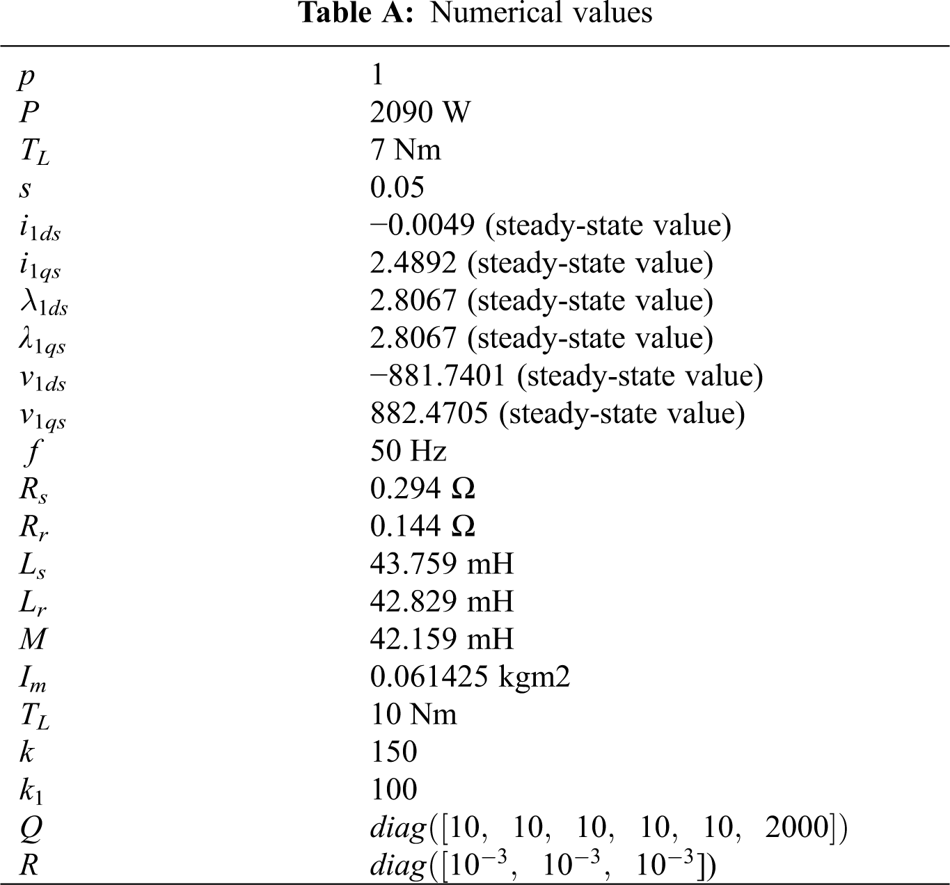
The Nomenclature of all variables is given in Tab. 1.
The stator flux direct and quadrature axis components are formulated to the stator currents direct and quadrature axis components as:
The rotor flux direct and quadrature axis components are formulated to the rotor currents direct and quadrature axis components as:
The formulation of the direct and quadrature axis components of the stator voltages are:
As the rotor in the SCIM used in this short circuit, then the direct and quadrature axis components of the rotor voltage are zero, and they can be defined as:
The motor torque is given by:
The differential equations that describe system variables can be defined as:
The state-space presentation of these differential Eqs. (10)–(12) can be defined as
where
For ‖y‖ < r → ‖f(y)‖ < lA, C is an observable pair
Proof.
The sub-observability matrix
In this section, a state observer is proposed. Let
L is chosen such that A − LC is a stability matrix, and there exists a symmetric positive definite matrix P such that:
Let
where
Choose the Lyapunov function
Time differentiation of V along the trajectories of e we obtain
For 4l‖P‖ < 1, which can be satisfied by choosing r. Hence e tends to zero asymptotically.
4 State Feedback Controller Based on Measurement of Load Torque
This section proposes a state feedback controller to regulate the induction motor's state to the desired value. Assume that the full state measurement and modifying it to incorporate the above state observer.
Substitute Eqs. (25)–(27) into (22) then
Choose the control
which leads to:
Consider the Lyapunov function
Time differentiating V along the trajectories of the system
for
Let
where
where
where
Expression
v1 = v1* + Me for some appropriate M
Choose lapunov function
Let
for
which proves the stability of the closed-loop system.
This section presents the simulation and numerical results based on state feedback controller with state observer using a backstepping technique which estimates the load torque, flux and current to regulate the speed of SCIM. The system is simulated for initial state variables and all numerical values given in the appendix. Two cases are investigated to assess the state observer's capability to estimate the speed of the motor, and the other is for evaluating the proposed controller besides the speed measurement. The Simulink MATLAB model of SCIM with feedback controller based on observer system shown in Fig. 1.

Figure 1: Simulink model of observer-based controller for induction motor system
Test Case 1: Constant Load Torque
The simulation results are performed at a constant load torque of 7 N.m. The SCIM measured and estimated speeds with the proposed observer-controller are investigated. The two-speed profiles converge to the desired speed with reasonable accuracy. In the case, estimating the speed using state observer using a backstepping technique, the maximum overshoot and settling time are 13%, 0.103 sec in comparison, they were 8% and 0.0603 sec when using the speed, was measured respectively. That indicates the efficiency and ability of the proposed speed measurement technique, as shown in Fig. 2. The stator direct and quadrature axis components through the proposed measured and estimated flux are shown in Figs. 3a and 3b.

Figure 2: Measured and estimated speed response with observer-based controller

Figure 3: Measured and estimated flux response a-Direct-axis flux response b- Quadrature-axis flux response
The direct and quadrature stator current components for the estimated and measured techniques are shown in Figs. 4a and 4b, respectively. From these results, the proposed stat observer could estimate the actual values of the motor speed, fluxes, and currents accurately without using any sensors.
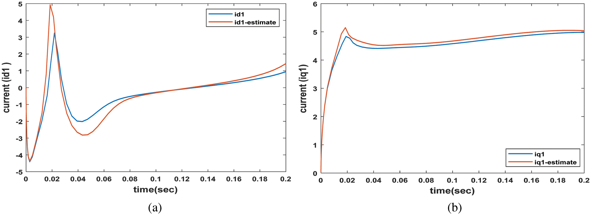
Figure 4: Measured and estimated current components a- Estimated direct current response b-Quadratic-axis current response
Test Case 2: Variable Load Torque
To test the motor speed proposed controller's effectiveness to keep the speed at predetermined (reference) value with load torque change, a sudden and large change in the load torque from 5 to 10 N.m between 0.06 and 0.14 s is applied. Another change from 10 to 7 N.m is simulated between 0.14 and 0.2 s as shown in Fig. 5 is presented.
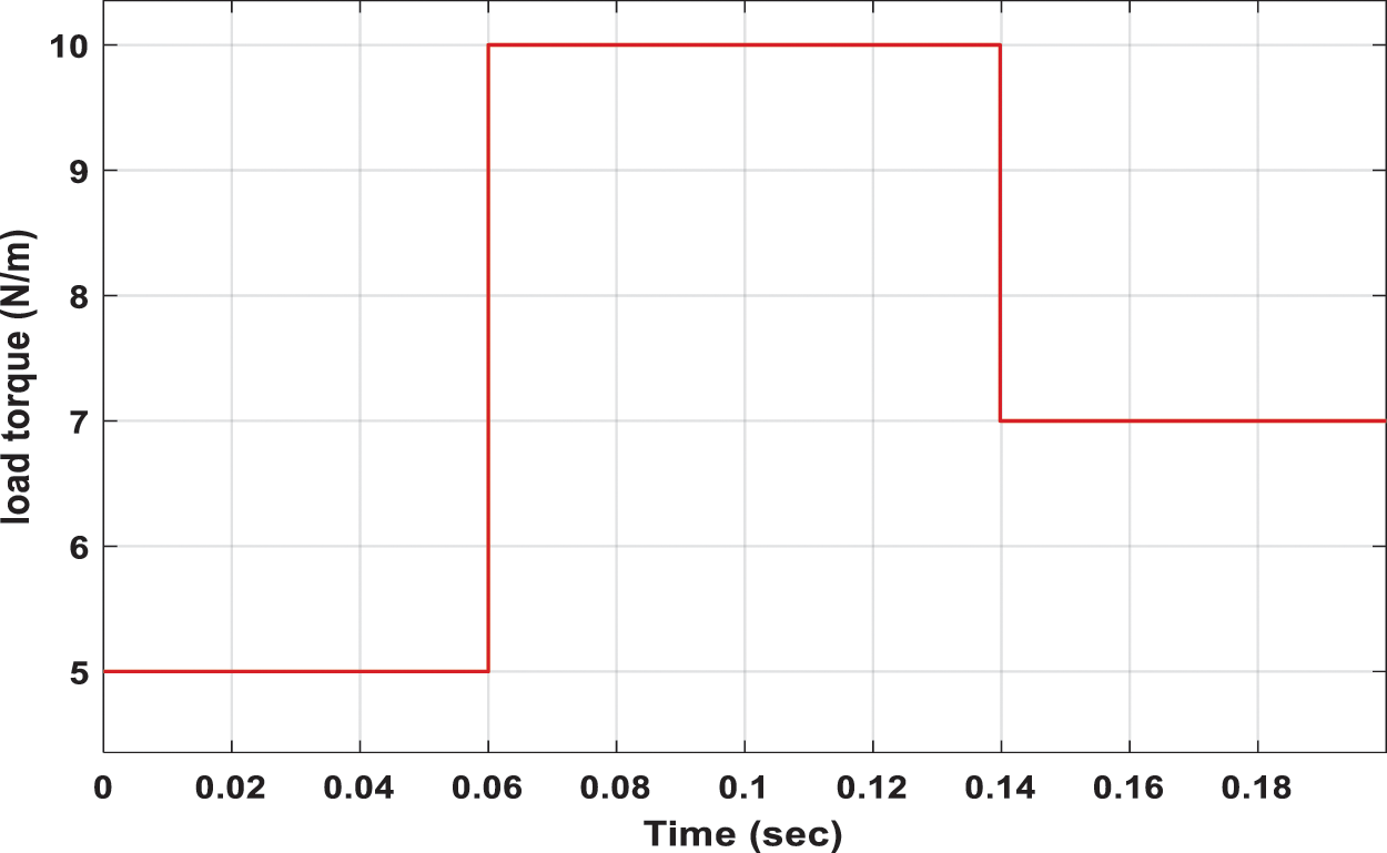
Figure 5: Load torque change
The proposed controller succeeded at regulating the motor speed at 300 rpm with this change in the load torque with a mostly identical speed profile for the measures and estimated speeds, as shown in Fig. 6.
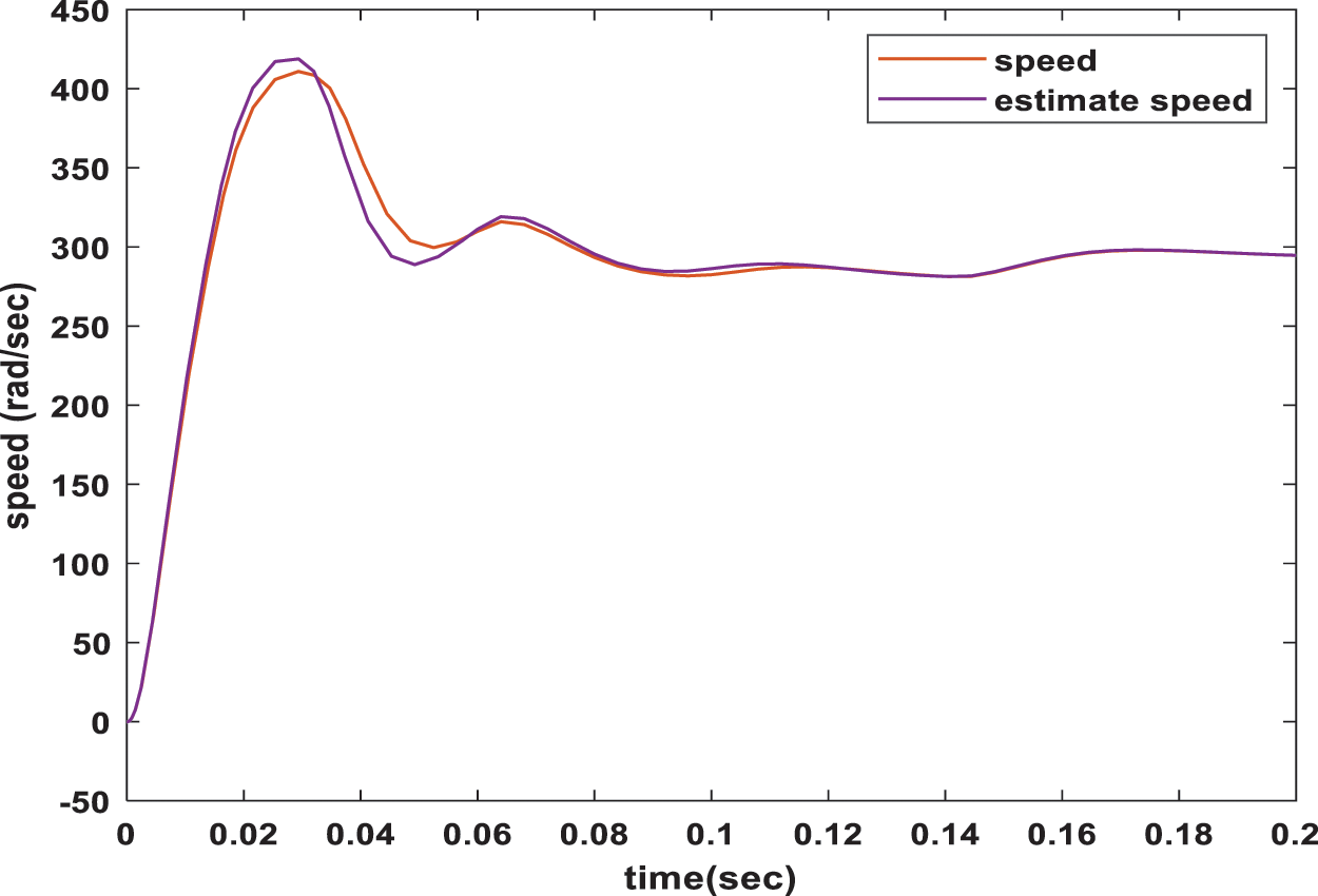
Figure 6: Measured and estimated speed response with the observer-based controller with load torque change
With the sudden and large change in the load torque applied in this case, the current increases to compensate for this increase in the load torque in both direct and quadrature components as given in Figs. 7a and 7b, respectively.
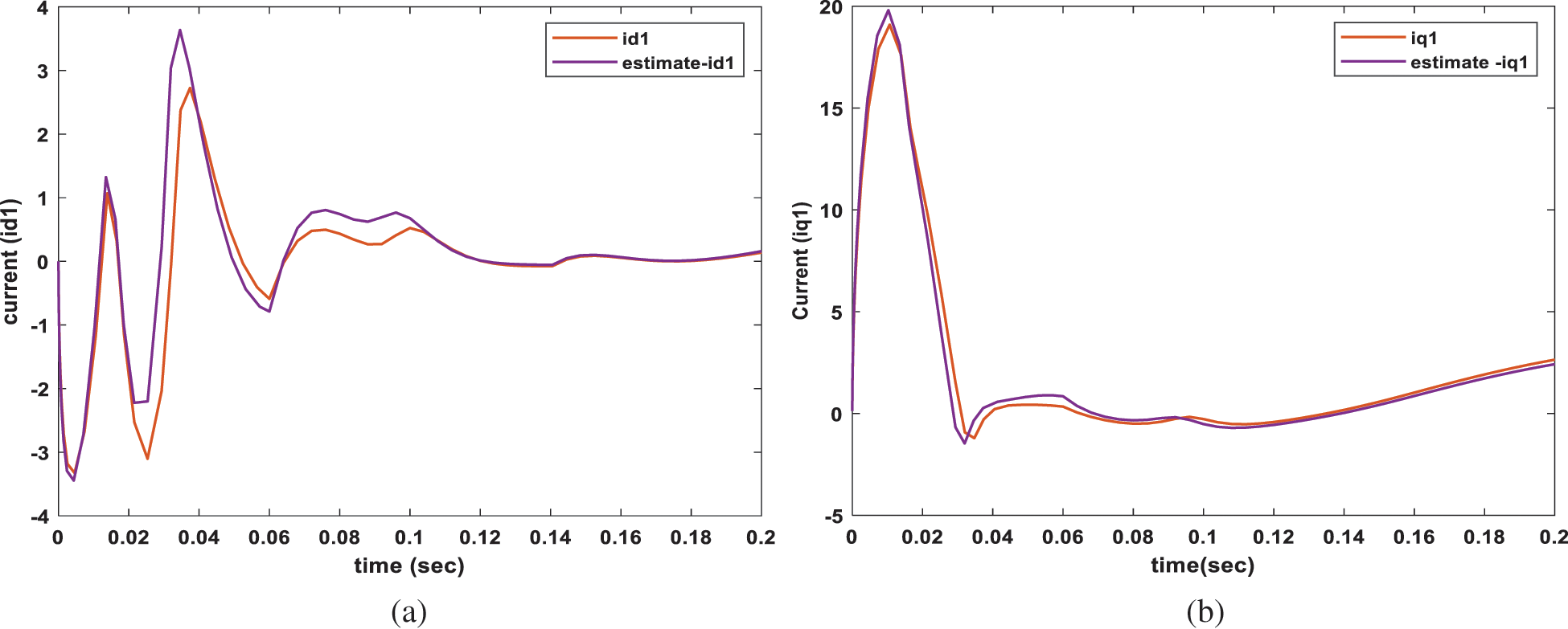
Figure 7: Measured and estimated current components at load change a- estimated direct current response b-quadratic current response
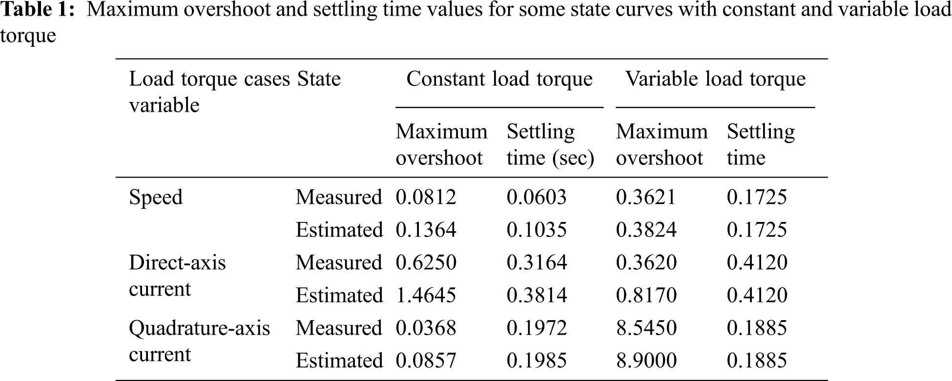
The mechanical torque deviation has a very speedy response and decayed to zero with a settling time of 0.08 s, as depicted in Fig. 8. The maximum overshoot and settling time values for some state curves with constant and variable load torque are listed in Tab. 1.

Figure 8: Mechanical torque response with variation of the load torque
From these results and discussions, the state feedback observer system's stability successfully estimated the load torque, estimated flux, and speed of SCIM. Besides, sensorless speed control of the motor under load variations.
In this paper, a robust speed regulator for speed sensorless induction motor is proposed, which considers the application of unknown load torque. The design is based on a fully nonlinear model of the induction motor and uses the backstepping technique to design an asymptotically stable observer-based output feedback controller to regulate the motor speed to any desired value in the presence of unknown load torque. Stability was proven using Lyapunov direct method and simulation results show the effectiveness of the proposed method. The results illustrate the proposed technique's capability in estimating and regulating the induction motor's speed effectively.
Funding Statement: The author(s) received no specific funding for this study.
Conflicts of Interest: The authors declare that they have no conflicts of interest to report regarding the present study.
1. S. Riaz, J. N. Chandra and D. Reddy, “Speed control of induction motor by using intelligence techniques,” International Journal of Engineering Research and Applications, vol. 5, pp. 130–135, 2015. [Google Scholar]
2. C. Chen, Y. Haisheng, F. Gong and W. Herong, “Induction motor adaptive backstepping control and efficiency optimization based on load observer,” Energies, vol. 13, 2020. [Google Scholar]
3. F. Farhani, A. Zaafouri and A. Chaari, “Gain-scheduled adaptive observer for induction motors: An LMI approach,” Acta Polytechnica Hungarica, vol. 11, pp. 49–61, 2014. [Google Scholar]
4. M. L. Song, “Research on speed sensorless vector control of induction motor based on full-order flux observer,” in Int. Con. on Materials Science, Energy Technology and Environmental Engineering, Shanghai, China, 2019. [Google Scholar]
5. D. Bullo, A. Ferraraand and M. Rubagotti, “Sliding mode observers for sensorless control of current-fed induction motors ACC,” in American Control Conference on O'Farrell Street, San Francisco, CA, USA, 2011. [Google Scholar]
6. L. X. Du, “Design of vector control system of induction motor without speed sensor,” Electronic Technology, vol. 30, pp. 110–113, 2017. [Google Scholar]
7. D. Wu, R. Lin and F. Tian, “Simulation analysis of asynchronous motor vector control system,” Electrical Switch, vol. 58, pp. 11–13, 2020. [Google Scholar]
8. D. Hu1, X. Deng and W. Zhu1, “Research on Speed Sensorless Control of Induction Motor Based on Back EMF,” Earth and Environmental Science, vol. 571, 2020. [Google Scholar]
9. S. Hussain and M. A. Bazaz, “Neural network observer design for sensorless control of I.M,” in IFAC Conf., India, pp. 106–111, 2016. [Google Scholar]
10. Y. Wang, L. Zhou, S. A. Bortoff, A. Satake and S. Furutani, “High gain observer for speed-sensorless motor drives: Algorithm and experiments,” in 2016 IEEE Int. Con. on Advanced Intelligent Mechatronics (AIM), pp. 1127–1132, 2016. [Google Scholar]
11. T. A. Razzaq, “Output feedback controller of electric drive based variable speed induction motors,” Association of Arab Universities Journal of Engineering Sciences, vol. 25, pp. 149–162, 2018. [Google Scholar]
12. M. S. Zaky, “A lyapunov method for stability analysis of piecewise-affine systems over non-invariant domains,” Int J Control, vol. 89, pp. 950–959, 2016. [Google Scholar]
13. A. Mahmoud, E. Hamdi, I. Atif, D. Ton and S. Ameena, “A novel sensorless control for multiphase induction motor drives based on singularly perturbed sliding mode observer-experimental validation,” Applied Sciences, vol. 10, pp. 1–24, April 2020. [Google Scholar]
14. B. O. Fan, F. Zhumu, L. Leipo and F. Jiangtao, “The full-order state observer speed-sensorless vector control based on parameters identification for induction motor,” Measurement and Control, vol. 52, pp. 202–211, 2019. [Google Scholar]
Appendix
 | This work is licensed under a Creative Commons Attribution 4.0 International License, which permits unrestricted use, distribution, and reproduction in any medium, provided the original work is properly cited. |