DOI:10.32604/iasc.2022.019959
| Intelligent Automation & Soft Computing DOI:10.32604/iasc.2022.019959 | |
| Article |
Model Predictive Control of H7 Transformerless Inverter Powered by PV
1Department of Electrical Engineering, Faculty of Engineering, University of Tabuk, Tabuk, 47913, Saudi Arabia
2Department of Electrical Power, Faculty of Engineering, Cairo University, Cairo, 12613, Egypt
3Renewable Energy & Energy Efficiency Centre (REEEC), University of Tabuk, Tabuk, 47913, Saudi Arabia
*Corresponding Author: Sherif Zaid. Email: shfaraj@ut.edu.sa
Received: 03 May 2021; Accepted: 08 June 2021
Abstract: Transformerless inverters have become an important integration of the modern photovoltaic (PV) grid-tied systems. Unfortunately, it has a general safety problem regarding the earth leakage current that must be less than the recommended standards. Lately, the H7 transformerless inverter, which is a three-phase inverter with an additional switch on the DC side, is introduced to mitigate the earth leakage current. Different modulation techniques and controllers are proposed to optimize its performance. This paper proposed the application of model predictive control (MPC) to grid-connected H7 transformerless inverter supplied by the PV power system. In modeling the system, the grid inductance has been taken into consideration. The inverter is linked with the PV through a boost converter. It is found that the boost converter inductance value has a great effect on the leakage current. Matlab's simulations for the proposed system are carried out. The performance of the proposed system controlled by MPC is compared to that controlled by the proportional-integral (PI) controller. The results show that the MPC gives the system greater benefits than the PI controller. The effects of the boost-converter inductance on the earth leakage current are studied. Also, the design of the boost-converter inductance is introduced.
Keywords: Photovoltaic; 3-φ transformerless inverter; H7; boost converter; model predictive control; earth leakage current; common-mode voltage
Solar photovoltaic (PV) energy sources have gained great importance in recent years. It is one of the most promising renewable energy sources that can meet the increasing demands of electrical energy in the future. The common advantages of the PV resources are availability everywhere, reliability, maintenance-free, no acoustic noise, long life, and no environmental pollution [1]. Nowadays, PV systems have become worldwide spread based on previous advantages. The PV systems may be utilized to deliver energy to the utility grid or standalone loads. Standalone PV systems are usually adapted for rural areas where the utility grid is not available. Otherwise, grid-connected PV systems are preferred over standalone ones due to high efficiency, low cost, optimum utilization of PV panels, and no storage requirement [2].
Traditionally, grid-connected PV systems use power transformers to match the voltage level to the grid, prevent DC currents injection into the grid, provide galvanic isolation between the PV panel and the grid, and ensure the quality of the grid injected-power. However, these transformers made the PV systems big in size, high in cost, and low efficiency. Recently, transformerless grid-connected PV systems are introduced to overcome the drawbacks of transformers [3–6]. These systems omit the power transformers and modify the power inverters’ modulations and topologies to act without a transformer. Hence, the inverters are called transformerless inverters. It may have a 1-φ or 3-φ topology according to the system power level. Three-phase transformerless inverters are usually used for power levels greater than 5 kW. Nevertheless, transformerless inverters have a serious safety problem named the earth leakage current. This current is greater than the recommended standards given by [7]. The main causes of the earth leakage current are the absence of the power transformer and the large parasitic capacitance of the PV panel. Previous research has shown that the inverter Common-Mode Voltage (CMV) is the source that drives the earth leakage current [8]. For 1-φ systems, many solutions for the earth leakage current problem are introduced [8–11]. However, in 3-φ systems, the problem is more complicated due to the 3-φ topology and high operating power.
In the literature, many transformerless inverter topologies have been introduced to solve the earth leakage current problem [12–28]. References [12,13], proposed many modulation strategies for the conventional two-level 3-φ inverter topology. It has been concluded that it is not possible to eliminate the leakage current without having additional switches. References [14,15], suggested four legs three-phase VSI with different modulation methods. However, the system was complex and the PWM modulation had restrictions of the zero-voltage vector application. Consequently, the total harmonic distortion of the output current has been degraded. Reference [16,17], proposed multilevel transformerless inverters including the neutral-point-clamped and the flying capacitor topologies. Although the leakage current was effectively reduced, the number of devices was increased, and the system efficiency was reduced. References [18,19], proposed H8 topology modulated with a simple PWM technique. The H8 topology consists of a three-phase inverter with two additional switches on each terminal of the DC side. Hence, the number of power switches was increased that increased the losses. Recently, a new topology called H7 was proposed [20–25]. The topology has the same configuration as the conventional 3-φ inverter except for a new series power switch. It can be considered as the promoted 3-φ version of the famous 1-φ transformerless inverter H5. In Reference [20,21], the H7 topology was derived using a new space vector modulation. Although the leakage current was slightly decreased, the efficiency was decreased. A modified topology with a modulation strategy named zero-voltage state rectifier was proposed by [22]. However, there was a voltage unbalance in the inverter capacitors. On the other hand, the current source inverter version of the transformerless H7 inverter has been suggested [23–25]. The current source H7 inverter has excellent current protection and enhances the utilization factor of the PV. Unfortunately, its large inductor degrades the system dynamics and increases its size.
Nowadays, Model Predictive Control (MPC) method has gained great attention in transformerless inverters control [26–29]. MPC has many advantages like the ease of implementation and the excellent fast dynamic performance. In reference [30], MPC control is implemented to T-type transformerless three-level inverter to reduce the leakage current. In [31,32], the MPC control scheme for the current control of a three-level NPC inverter is proposed.
This paper proposes a PV powered H7 transformerless inverter controlled by the MPC algorithm. The transformerless inverter is linked to the grid via an LC filter. The discrete model of the system, considering the output LC filter and the internal impedance of the grid, is derived. The first objective of the paper is to apply the MPC control algorithm to grid-connected H7 transformerless inverter powered by a PV panel. Hence, the performance of the system is compared to that utilizes a PI controller. The second objective is to study the factors affecting the earth leakage current value such as the inductance of the boost converter. The effects of the boost-converter inductance on the earth leakage current are studied. Also, the design of the boost-converter inductance is introduced.
The work in this paper starts by generating the CMV model of the system including the inductance of the boost converter. Also, the discrete-time model of the system is derived to generate the MPC controller algorithm. Then, the proposed system and controllers are simulated using Matlab/Simulink platform. Consequently, the performance of the proposed system is measured and the effect of the boost converter inductance on the leakage current is studied. Also, two controllers are adapted for the system MPC and the conventional PI controller. The paper is organized as follows: Section 2 describes the proposed system. The Earth leakage current path and CMV model of the H7 inverter are presented in Section 3. Section 4 discusses the analysis and design of the MPC controller for the H7 transformerless inverter. The Maximum Power Point Tracking (MPPT) algorithm is discussed in Section 5. Section 6 discusses the details of the simulation results, while Section 7 provides the paper conclusions.
The proposed system is a PV powered grid-connected H7 transformerless inverter as shown in Fig. 1a. The nominal power rating of the system is 11 kW and the utility grid is 3-φ (230 V, 50 Hz). The system consists of a PV panel that generates the input DC power to a boost converter. The boost converter controls the PV panel terminal voltage and current. The boost converter is an important part to support the MPPT operation of the PV. Also, the boost-converter input-inductor, as will be shown, provides extra impedance to the earth leakage current. The terminals of the boost converter output represent the DC-link, which is attached to the input of the H7 transformerless inverter. H7 three-phase transformerless inverter represents a very suitable solution to reduce the ground leakage current while adding only one switch to the conventional three-phase bridge inverter as shown in Fig. 1b. H7 transformerless inverter is considered as an extended version of the well-known H5 single-phase transformerless inverter. The basic idea of the H7 inverter is to disconnect the PV panels from the grid during freewheeling periods and as a result, there will be no path for leakage. The seventh switch Q7 conducts during active modes (vectors

Figure 1: (a) The proposed PV powered grid-connected H7 transformerless inverter (b) The H7 transformerless inverter topology
3 Earth Leakage Current Path and CMV Model
The path of the earth leakage currents may be investigated with the help of the power circuit diagram of the system Fig. 2. Where; LB is the boost converter inductance, Cleakage is the stray capacitance of the PV panel, and Lg is the ground inductance of the grid. The inverter can be modeled as three voltage sources (VAN, VBN, and VCN) [3]. Note that, the voltages are referred to as the common point “N”. These voltage sources have a square wave nature that depends on the PWM modulation technique used for the inverter switches. Assume that the phase equivalent impedances are (ZA, ZB, and ZC). Hence, the proposed H7 system model is shown in Fig. 3a. Previous research manipulated this circuit using differential and common mode model techniques [3,19]. In this paper, another method of analysis is used as explained below. Assume a balanced 3-φ system (va, vb, vc are balanced and ZA = ZB = ZC where; ZA = ωLA) and apply Thevenin's theorem to the points N-O. The three parallel branches of the circuit can be reduced to a single voltage source and impedance given by:

Figure 2: The proposed system power circuit diagram
Hence, the equivalent circuit is shown in Fig. 3b. This simple circuit represents the earth leakage current path. Notice that the present voltage source is the common-mode voltage CMV. Consequently, reducing the CMV fluctuations will result in a reduction of the earth leakage current. The value of the CMV depends mainly on the modulation technique and the inverter switching frequency. Another way to reduce the leakage current is accomplished by increasing the path impedances XB, ZA, and XCG, where; XCG = ωLCG. However, (ZA, and XCG) have critical values and cannot be increased. On the other hand, the value of XB can affect greatly the earth leakage current. The effects of the XBvalue and configuration on the earth leakage current will be studied in the simulation results section.
In general, the CMV of the H7 inverter can calculated as follows [21]:
It is well known that the terminal voltages of the inverter depend on the switching state of the switches. However, the H7 inverter states are the same eight states as the conventional 3-φ inverter. These states generate eight corresponding voltage vectors, as shown in Fig. 2. Referring to Fig. 2 and during the active mode
The same calculations can be carried out for the other five active vectors. The results are summarized in Tab. 1. When applying the zero-voltage vector

Also, applying the zero vector
As indicated in the previous paragraphs the zero vectors (
4 MPC of the H7 Transformerless Inverter
The first step of designing the MPC controller is to generate the discrete-time model of the system. The model of the H7 transformerless inverter may be derived as follows:
Assume that:
• (lg) is the grid inductance, (Cf) is the filter capacitance, and (Lf) is the filter inductance.
• Any 3-φ quantity (ua, ub, and uc) are represented as space vectors

Figure 3: (a) The proposed system model, replacing the inverter with equivalent voltage sources. (b) The leakage current path equivalent circuit model of the proposed system
Refer to Fig. 3, the voltage-current relations may be written as:
where (
The group of Eqs. (8) to (10) represents the system electrical dynamic model. It is useful to write these equations in the state-space matrix form as:
where; (
Applying Euler approximation [34] to Eq. (12) for a sampling time Ts, the discrete-time state-space model is obtained:
Note that, (
where; (i*gα, i*gβ) are the real and imaginary components of the grid current reference, (igα, igβ) are the real and imaginary components of the grid current.
5 Design of the Boost Converter Inductor and Grid Filter
Simple procedures for designing the inductor of the boost converter and grid filter elements of the proposed system are presented in this section.
5.1 Boost-Converter Inductor Design
As stated before, the boost converter inductance has the main role in reducing the earth leakage current. Hence, the design of this inductor is important in building the proposed system. The factors affecting the inductor design value are:
• The mode of operation of the converter whether it is continuous or discontinuous. In our case, the continuous conduction mode is mandatory for MPPT operation.
• The maximum ripple current required (ΔIpv) for the PV. This ripple must be kept as small as possible to get precise MPPT operation. Usually, ΔIpv is kept below 5% of the rated PV current [35].
• The operating switching frequency of the boost converter (fB). In the case of utilizing hysteresis controllers, the average switching frequency is used.
• The design is usually constrained by the copper losses and the saturation level of the inductor.
Assuming that the DC-link capacitor is large enough, the following equations can be written [35]:
One way to ensure stability and continuous operation is to choose a large enough inductor so that the ripple current is greater than twice the minimum DC-link current. From Eqs. (16)–(18) the inductance value can be calculated using:
where; (d) is the converter duty ratio and (Ipv|min) is the minimum PV current. This value of LB is the minimum to get the required ripple. Another constraint for the vale of LB is the earth leakage current limit that can be derived from Fig. 5 and given by:
If the leakage current given by (20) is within the recommended standards, then the value of LB is satisfactory. Otherwise, the value of LB must be increased so that Eq. (20) obeys the standards. An important note is that the large values of LB will produce a large cost, large space, and slow response of the system. Hence, the minimum value of LB, which satisfies all the above constraints, must be used.
In our proposed system, an LCL filter is used between the inverter and the grid to attenuate the switching frequency harmonics generated by the H7 inverter. The LCL filter has a better dynamic characteristic, better harmonics-attenuation capacity, and better decoupling between the filter and the grid impedance [36]. The design procedure of the grid filter is as follows:
• The inverter side filter inductance Lf is designed to limit the output current ripple (ΔImax) to 10% of the rated peak [37]:
It is important to note that, (Lf) calculated by Eq. (21) is the minimum value that limits the output ripple current. Assuming that the current ripple is 10% of the rated grid current:
where; (Eg, and Pg) are the grid rms line voltage and rated power respectively; (fsw) is the inverter minimum switching frequency.
• The design of the filter capacitor Cf proceeds from the fact that the acceptable variation of the grid power factor is 5%. Hence [36]:
• The grid side inductance ( Lg) can be calculated as:
• Finally, the resonant frequency of the filter is adapted. This frequency must be distant from the utility frequency and should be greater than 50% of the fsw to get high filtration around the converter switching frequency. The resonant frequency (fo) can be calculated as:
The proposed system consists of three controllers or control loops. The first controller is the MPPT controller that adjusts the PV operating point to be very close to the MPPT conditions. The MPPT algorithm will generate the reference current to a current-regulated boost converter which in turn maintains the MPPT conditions. The second controller is the DC-link voltage controller that regulates Vdc at a specified value. The third controller is used to regulate the grid current of the H7 transformerless inverter controller. The details of those controllers are explained in the next paragraphs.
Good utilization of the PV systems can be achieved by absorbing as much power as possible from the PV. The technique used to do this job is commonly known as the MPPT algorithm. Commonly, the MPPT becomes an essential part of the PV systems. Too many approaches and algorithms have been proposed for MPPT [38–39]. For this research, the incremental conductance MPPT algorithm is utilized. The idea of this technique is to track the maximum points of the PV (Watt – Volt) curve as shown by [6]:
This MPPT algorithm is implemented to generate the reference PV current (I*pv) to a current-controlled boost converter shown in Fig. 4a. Comparing this reference to the measured value (Ipv), the generated error signal will derive an on-off controller. This controller generates the boost converter switch pulses.

Figure 4: (a) The block diagram of the MPPT controller, (b) The block diagram of the DC-link voltage controller and the MPC controller
6.2 DC-Link Voltage Controller
This controller regulates the DC-link voltage which is an important role in the power transfer and stability of the whole system. It generates the reference grid's current value, as shown in Fig. 4b. For stability issues, the response of this controller must be slower than the inverter controller. Fortunately, the huge capacitor value at the DC-link terminals decelerates the response of the system. As the set value is constant, the PI controller is adequate. The control function is given by:
The PI controller parameters (kP, kI) are tuned by the Ziegler-Nichols procedure.
6.3 MPC Controller of the Grid Current
The MPC scheme is based on predicting the future manipulated variables of the model to improve the system performance. However, the MPC schemes with power electronics systems are different. This comes from the nature of the power electronics systems that always use power converters. Generally, these converters have a limited number of feasible switching states. In those cases, the procedure depends on selecting the switching state which makes the system output close as possible to its respective references for each sampling period. Thus, for each sampling state, the behavior of the variables can be predicted by using the system model. Then, an optimization is adapted and applied to ensure selecting the appropriate and optimal switching state. This optimization is defined as a cost function that will be assessed for every promising switching state. Then, the optimal and suitable switching state is selected based on the minimization of the cost function obtained. The control structure of the proposed system is illustrated in Fig. 4b. The objectives of this controller are to control the grid current vector (
In the literature of the grid-connected transformerless PV systems, the inverter usually operates at unity power factor and injects real power into the grid [2]. Unity power factor operation will lead to simplify the control algorithms of the global power system operations. It is generated by multiplying the reference amplitude by a unity sinusoidal wave generated by the grid synchronization circuit. However, the MPC output is the optimum switching state that precisely fit the grid current reference. The procedure of the MPC algorithm starts with the sample period (k) by the prediction process relies on measuring the grid current Ig(k), the grid voltage Vg(k), and the capacitor voltage Vc(k). Then, the grid current value, Ig(k + 1), is predicted for the next sample by using the discrete-time model of Eq. (14). Hence, the cost function is assessed for all the switching states. Finally, the switching state which minimizes the cost function is sent to the inverter switches for the next sampling period.
To validate the paper idea, a Matlab simulation for the proposed system shown in Fig. 1a is prepared. The system parameters listed in Tab. 2 are selected for a PV system of power rating 11KW connected to a 3-φ (230 V, 50 Hz) utility grid. The system sampling time is adapted to complete the process of the control algorithm. The PV panel consists of six parallel strings. Each string is formed of 960 series cells. The boost converter is currently controlled using a hysteresis controller that has a band (Δh) of 5%. The set value of the boost controller is the MPPT current of the PV at the given insulation level. The stability of the system is related directly to the DC-link voltage level stability. Hence, the DC-link voltage is also controlled using a simple PI controller. The parameters of the PI controller are calculated with the help of Ziegler-Nichols common technique. The H7 inverter is current-controlled using MPC to achieve sinusoidal grid currents with a unity power factor. The reference grid current is set by the PI controller of the DC-link voltage. It is important to note that, a modulation unit must be utilized with the PI controller to generate the gate pulses of the inverter. In this paper, the sinusoidal PWM is employed. However, the MPC controller generates the pulses directly according to the cost function.

Fig. 5 compares the results of the proposed H7 transformerless inverter controlled by the PI current controller (Fig. 5a) and MPC controller (Fig. 5b). Both controllers have balanced 3-φ grid currents with a unity power factor. The instantaneous inverter terminal voltages are not the same for the two controllers. This can be explained as the voltage vector selected by each controller depends on the control action that differs from one controller to another. Also, there are some odd pulses on VAB in the MPC case. This occurs because the controlled variable of the inverter is the grid current and the inverter voltage is the control action. Hence, the inverter terminal voltage may have some sort of such spikes. The MPPT controller is the same for both systems. The MPPT controller forces the PV currents to track the MPPT reference current. The MPC controller has a very small leakage current compared to the PI controller case. The CMV responses of the two controllers are shown in Fig. 6a. The CMV levels for the two controllers are restricted to
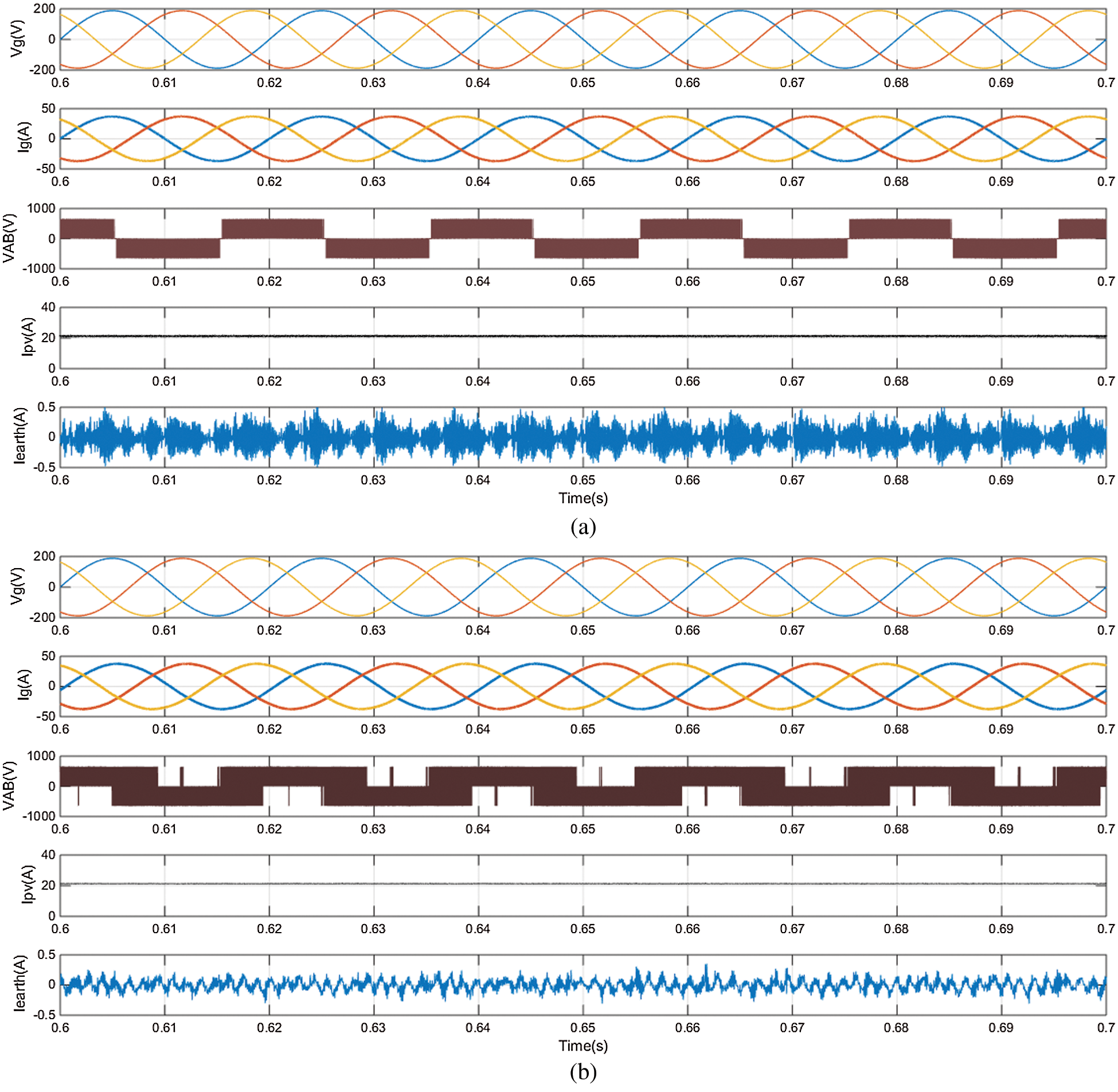
Figure 5: Simulation results Vg, Ig, Ipv, VAB, and Iearth of the proposed H7 transformerless inverter with (a) Conventional PI controller and (b) MPC controller
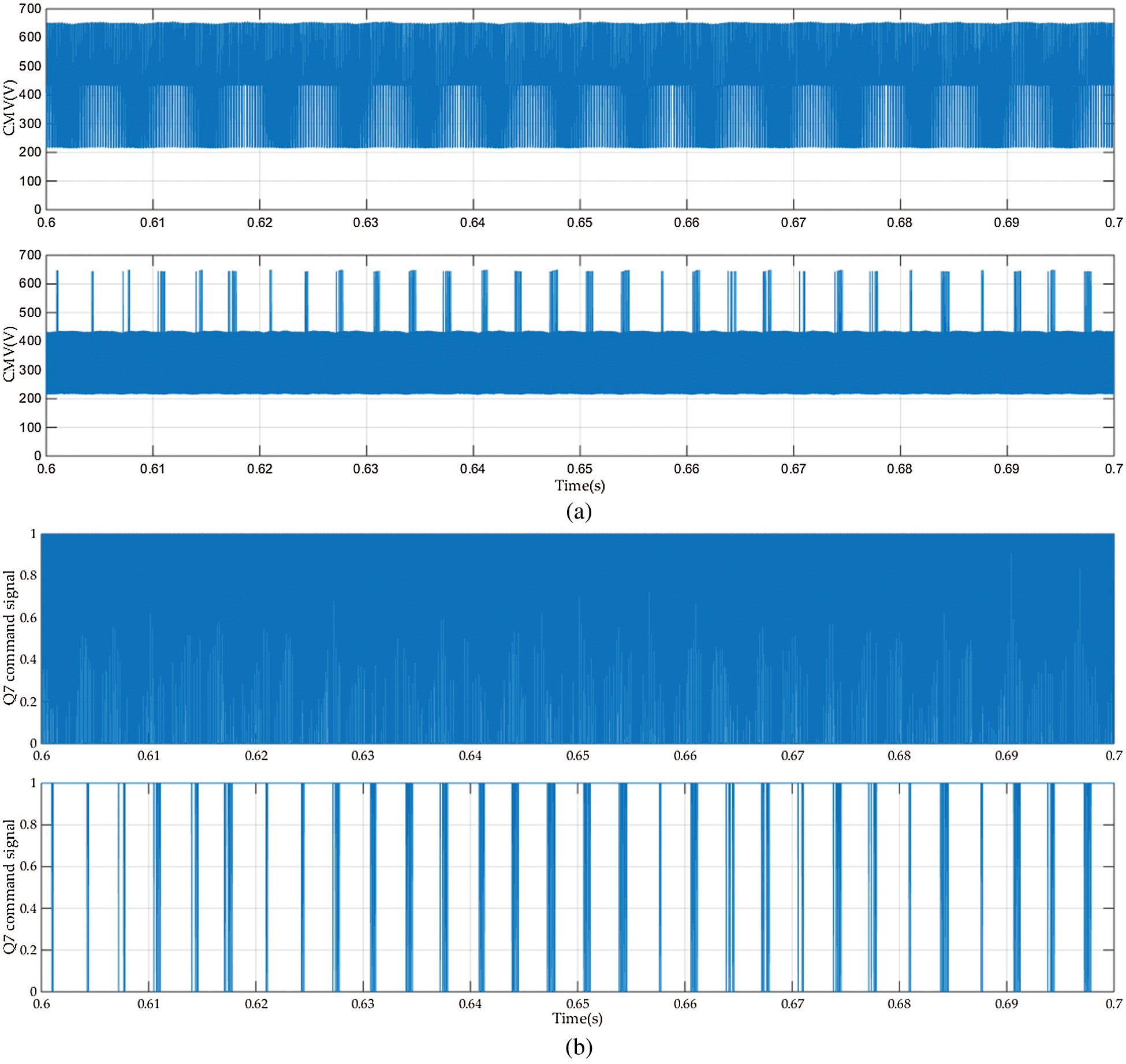
Figure 6: (a) The CMV voltage (b) The command signal for Q7 for the conventional PI controller (upper) and MPC controller (lower)
Fig. 7 compares the earth leakage current value and the THD for the two controllers as follows:
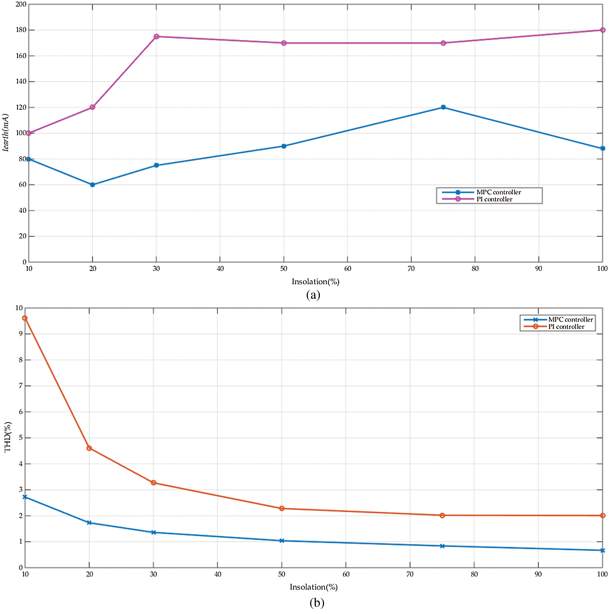
Figure 7: The variation of (a) Iearth(rms) and (b) THD of the grid current vs. the insolation level for both the MPC and PI controllers
The variation of the earth leakage current Iearth (rms) vs. the insolation level is shown in Fig. 7a. It compares the values obtained with the MPC controller to the conventional PI controller. The MPC controller has a lower leakage current than the PI one and it is within the standards range. The reduction in the leakage current changes with the insolation level, from 50% to 80%. It can be concluded that the average reduction in the earth leakage current is near ≅ 65%. Nevertheless, the leakage current values with the two controllers are within the standards range. Fig. 7b shows the changes of the THD of Ig with the insulation level for both controllers. Also, the THD of the MPC controller is usually lower than that of the PI controller. The reduction in the THD changes with the insolation level, from 25% to 30%. It can be concluded that the average reduction in the THD of the grid current is near ≅ 27.5%. However, at low insolation levels, the THD with the PI controller becomes higher than the recommended standards [40].
The frequency spectrum of the grid current at 100% insolation level is compared for the two controllers as shown in Fig. 8a and Fig. 8b. The THD of the grid current is 0.67% in the case of the MPC controller however, it is 2.01% in the case of the PI controller. The harmonic content in the case of MPC is lower than the PI case. The spectrum of the PI case, Fig. 11a, shows subgroup harmonics at the PWM switching frequency (8KHz). Hence, the MPC controller provides a better harmonic spectrum.
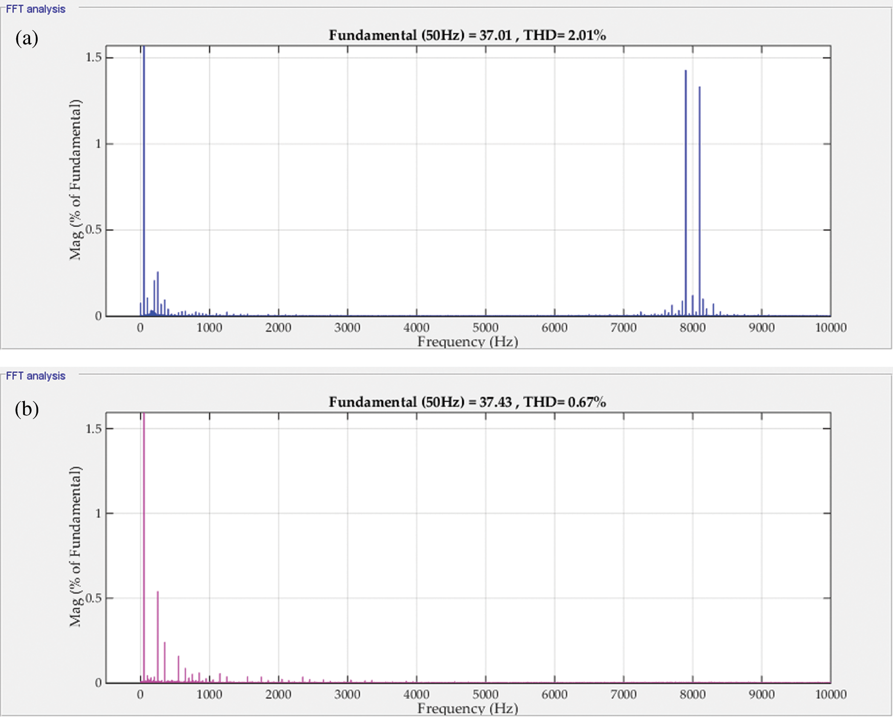
Figure 8: The spectrum of Ig for (a) PI current controller (b) MPC controller (@100%insolation)
The system efficiency variation with the insolation level for the MPC controller is shown in Fig. 9. It is noted that the efficiency of the system has the same values for the two controllers. The Californian-efficiency [34] is calculated to be 95.62%. The losses distribution of the proposed system can be summarized in Tab. 2. The main sinks for the system losses are the switching or active devices, system inductors, and ohmic losses. The active devices losses are the sum of the conduction and switching losses [35]. As it can be seen in Tab. 3., Q1, Q3, and Q5 have almost the same power losses of nearly 4% while Q2, Q4, and Q6 have around 2.8%. This occurred because of using only
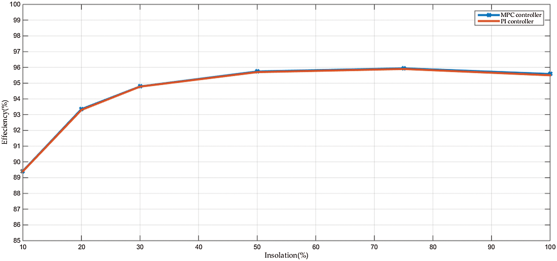
Figure 9: The system efficiency variations with the insolation level for the MPC and PI controllers

As seen from the results that the boost converter inductance position has a great effect on the leakage current value. It is thought that the value of LB can affect the leakage current. Fig. 10a shows the effect of varying the boost inductance value on the switching frequency of the boost converter. The results, presented in Fig. 10a, are nearly the same for the two controllers. As the inductance increases, the switching frequency decreases. This occurs due to the presence of the hysteresis current controller and the nature of the inductance resists the change in the current. As the inductance increases, the resistance of current change increases. Hence, the hysteresis controller switching durations are prolonged. Consequently, the switching frequency decreases. The rms value of the earth leakage current is affected by varying the boost inductance value, as shown in Fig. 10b. It is noted that as the inductance value decreases the leakage current increases and vice versa. This can be concluded by inspection from the common mode equivalent circuit of Fig. 5.

Figure 10: The effect of changing the boost converter inductance “LB”, using MPC controller and PI controller, on (a) The boost converter switching frequency (b) The earth leakage current
Fig. 11 shows the response of the system output power to the grid and the input MPPT power from the PV in the case of the PI controller (Fig. 11a) and the MPC controller (Fig. 11b). For both cases, the grid output power tracks the PV MPPT power. The system losses show an error between the PV power and the output power. The losses in the two cases are nearly the same. Hence, the efficiency of the system does not change with the controller type.
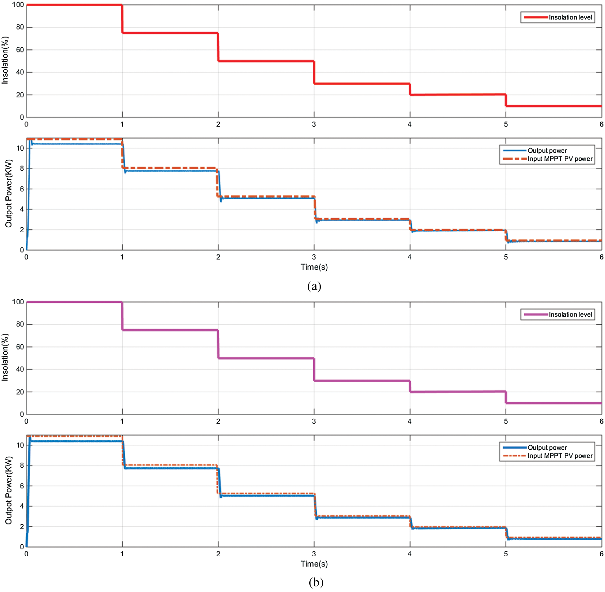
Figure 11: The MPP power, output power at step insolation variations with (a) Conventional PI controller, and (b) MPC controller
Fig. 12 compares the transient response of Ipv, Ig, and Vdc of the proposed H7 transformerless inverter with (a) conventional PI controller and (b) MPC controller. In general, the overshoots and settling times at the step change times are reduced with the MPC case compared to the PI controller one.

Figure 12: The transient response of Ipv, Ig, and Vdc of the proposed H7 transformerless inverter with (a) Conventional PI controller and (b) MPC controller
This paper proposed the implementation of the MPC technique to a grid-connected H7 transformerless inverter powered by a PV panel. A boost converter is integrated between the PV panel and the H7 inverter. The effects of the boost converter inductance values on the earth leakage current are studied. The common-mode equivalent circuit of the leakage current path is derived. For designing the MPC controller, the system discrete-time model is generated. The grid leakage inductance has been taken into consideration in the model. Then, the control algorithm of the MPC is developed. The proposed system is simulated using Matlab/Simulink package. Comprehensive comparisons for the proposed system performance controlled by MPC with the conventional PI controller are carried out. The simulation results show that the rms value of the leakage current with the MPC case is greatly reduced compared to the conventional H7 controlled by PI controllers. The average reduction in the leakage current is around 65% compared to the PI controller. The grid currents were sinusoidal with a unity power factor for the two controllers. Also, the THD of the grid current has been reduced to nearly 27.5% of the PI controller. However, the THD and the earth leakage current were within the recommended standards for the two controllers. Nevertheless, at low insolation levels, the THD with the PI controller becomes higher than the recommended standards. The effects of the boost-converter inductance on the earth leakage current are studied. It can be concluded from the simulation results that the boost converter inductor design value affects greatly the earth leakage current value.
Acknowledgement: The author would like to acknowledge the Renewable Energy & Energy Efficiency Centre (REEEC) of Tabuk University for its great support.
Funding Statement: This research was funded by the University of Tabuk, Grant Number S-1441-0055 and S-1441-0172 at https://www.ut.edu.sa/web/deanship-of-scientific-research/home.
Conflicts of Interest: The authors declare that they have no conflicts of interest to report regarding the present study.
1. F. Blaabjerg, T. Teodorescu, M. Liserre and A. V. Timbus, “Overview of control and grid synchronization for distributed power generation systems,” IEEE Transactions on Industrial Electronics, vol. 53, no. 5, pp. 1398–1409, 2006. [Google Scholar]
2. S. B. Kjaer, J. K. Pedersen and F. Blaabjerg, “A review of single-phase grid-connected inverters for photovoltaic modules,” IEEE Transactions on Industrial Applications, vol. 41, no. 5, pp. 1292–1306, 2005. [Google Scholar]
3. D. Meneses, F. Blaabjerg, Ó. García and J. A. Cobos, “Review and comparison of step-up transformerless topologies for photovoltaic AC-module application,” IEEE Transactions on Power Electronics, vol. 28, no. 6, pp. 2649–2663, 2013. [Google Scholar]
4. H. Xiao, S. Xie, Y. Chen and R. Huang, “An optimized transformerless photovoltaic grid-connected inverter,” IEEE Transactions on Industrial Electronics, vol. 58, no. 5, pp. 1887–1895, 2011. [Google Scholar]
5. G. Petrone, G. Spagnuolo, R. Teodorescu, M. Veerachary and M. Vitelli, “Reliability issues in photovoltaic power processing systems,” IEEE Transactions on Industrial Electronics, vol. 55, no. 7, pp. 2569–2580, 2008. [Google Scholar]
6. S. A. Zaid and A. M. Kassem, “Review, analysis and improving the utilization factor of a PV-grid connected system via HERIC transformerless approach,” Renewable Sustainable Energy Reviews, vol. 73, pp. 1061–1069, 2017. [Google Scholar]
7. DIN V VDE V 0126-1-1, VDE Press, 2006. [Google Scholar]
8. R. Gonzalez, J. Lopez, P. Sanchis and L. Marroyo, “Transformerless inverter for single-phase photovoltaic systems,” IEEE Transactions on Power Electronics, vol. 22, no. 2, pp. 693–697, 2007. [Google Scholar]
9. T. Kerekes, R. Teodorescu, P. Rodríguez, G. Vázquez and E. Aldabas, “A new high-efficiency single-phase transformerless PV inverter topology,” IEEE Transactions on Industrial Electronics, vol. 58, no. 1, pp. 184–191, 2011. [Google Scholar]
10. T. K. S. Freddy, N. A. Rahim, W. Hew and H. S. Che, “Comparison and analysis of single-phase transformerless grid-connected PV inverters,” IEEE Transactions on Power Electronics, vol. 29, no. 10, pp. 5358–5369, 2014. [Google Scholar]
11. H. Elbalawi and S. A. Zaid, “H5 transformerless inverter for grid-connected pv system with improved utilization factor and simple maximum power point algorithm,” Energies, vol. 11, no. 11, pp. 2912, 2018. [Google Scholar]
12. T. Kerekes, R. Teodorescu, M. Liserre, C. Klumpner and M. Sumner, “Evaluation of three-phase transformerless photovoltaic inverter topologies,” IEEE Transactions on Power Electronics, vol. 24, no. 9, pp. 2202–2211, 2009. [Google Scholar]
13. C. Hou, C. Shih, P. Cheng and A. M. Hava, “Common-mode voltage reduction pulsewidth modulation techniques for three-phase grid-connected converters,” IEEE Transactions on Power Electronics, vol. 28, no. 4, pp. 1971–1979, 2013. [Google Scholar]
14. F. Hasanzad, H. Rastegar and M. Pichan, “Performance evaluation of space vector modulation techniques for reducing leakage current of a three-phase four-leg PV inverter,” in Proc. 17th Iranian Conf. on Electrical Engineering (ICEETehran, Iran, pp. 1026–1031, 2017. [Google Scholar]
15. X. Guo, R. He, J. Jian, Z. Lu, X. Sun et al., “Leakage current elimination of four-leg inverter for transformerless three-phase pv systems,” IEEE Transactions on Power Electronics, vol. 31, no. 3, pp. 1841–1846, 2016. [Google Scholar]
16. X. Guo, B. Wei, T. Zhu, Z. Lu, L. Tan et al., “Leakage current suppression of three-phase flying capacitor pv inverter with new carrier modulation and logic function,” in IEEE Transactions on Power Electronics, vol. 33, no. 3, pp. 2127–2135, 2018. [Google Scholar]
17. A. K. Gupta, H. Agrawal and V. Agarwal, “A novel three-phase transformerless H-8 topology with reduced leakage current for grid-tied solar pv applications,” IEEE Transactions on Industry Applications, vol. 55, no. 2, pp. 1765–1774, 2019. [Google Scholar]
18. C. T. Morris, D. Han, and B. Sarlioglu, “Reduction of common mode voltage and conducted EMI through three-phase inverter topology,” IEEE Transactions on Power Electronics, vol. 32, no. 3, pp. 1720–1724, 2017. [Google Scholar]
19. L. Concari, D. Barater, G. Buticchi, C. Concari and M. Liserre, “H8 inverter for common-mode voltage reduction in electric drives,” IEEE Transactions on Industry Applications, vol. 52, no. 5, pp. 4010–4019, 2016. [Google Scholar]
20. X. Guo, D. Xu and B. Wu, “Three-phase seven-switch inverter with common mode voltage reduction for transformerless photovoltaic system,” in Proc. 40th IECON - 2014, Dallas, TX, USA, pp. 2279–2284, 2014. [Google Scholar]
21. T. K. S. Freddy, N. A. Rahim, W. Hew and H. S. Che, “Modulation techniques to reduce leakage current in three-phase transformerless H7 photovoltaic inverter,” IEEE Transactions on Industrial Electronics, vol. 62, no. 1, pp. 322–331, 2015. [Google Scholar]
22. X. Guo, X. Zhang, H. Guan, T. Kerekes and F. Blaabjerg, “Three-phase ZVR topology and modulation strategy for transformerless pv system,” IEEE Transactions on Power Electronics, vol. 34, no. 2, pp. 1017–1021, 2019. [Google Scholar]
23. E. Lorenzani, G. Migliazza, F. Immovilli, C. Gerada, H. Zhang and G. Buticchi, “Internal current return path for ground leakage current mitigation in current source inverters,” IEEE Access, vol. 7, pp. 96540–96548, 2019. [Google Scholar]
24. X. Guo, “Three-phase ch7 inverter with a new space vector modulation to reduce leakage current for transformerless photovoltaic systems,” IEEE Journal of Emerging and Selected Topics in Power Electronics, vol. 5, no. 2, pp. 708–712, 2017. [Google Scholar]
25. W. Wang, F. Gao, Y. Yang and F. Blaabjerg, “Operation and modulation of h7 current-source inverter with hybrid sic and si semiconductor switches,” IEEE Journal of Emerging and Selected Topics in Power Electronics, vol. 6, no. 1, pp. 387–399, 2018. [Google Scholar]
26. I. S. Mohamed, S. A. Zaid, H. M. Elsayed and M. F. Abu-Elyazeed, “Implementation of model predictive control for a three-phase inverter with output LC filter on eZdsp f28335 Kit using HIL simulation,” International Journal of Modelling, Identification, and Control, vol. 25, pp. 301–312, 2016. [Google Scholar]
27. S. Vazquez, J. I. Leon, L. G. Franquelo, J. Rodriguez, H. A. Young et al., “Model predictive control: A review of its applications in power electronics,” IEEE Industrial Electronics Magazine, vol. 8, no. 1, pp. 16–31, 2014. [Google Scholar]
28. I. S. Mohamed, S. A. Zaid, M. F. Abu-Elyazeed and H. M. Elsayed, “Improved model predictive control for three-phase inverter with output LC filter,” International Journal of Modelling, Identification and Control, vol. 23, no. 4, pp. 371–379, 2015. [Google Scholar]
29. S. Mohamed, S. Rovetta, T. D. Do, T. Dragicević and A. A. Z. Diab, “A neural-network-based model predictive control of three-phase inverter with an output LC filter,” IEEE Access, vol. 7, pp. 124737–124749, 2019. [Google Scholar]
30. W. Xiaodong, J. Zou, L. Ma, J. Zhao, C. Xie et al., “Model predictive control methods of leakage current elimination for a three-level T-type transformerless PV inverter,” IET Power Electronics, vol. 11, no. 8, pp. 1492–1498, 2018. [Google Scholar]
31. R. Vargas, P. Cortes, U. Ammann, J. Rodriguez and J. Pontt, “Predictive control of a three-phase neutral-point-clamped inverter,” IEEE Transactions on Industrial Electronics, vol. 54, no. 5, pp. 2697–2705, 2007. [Google Scholar]
32. H. Albalawi and S. A. Zaid, “Performance improvement of a grid-tied neutral-point-clamped 3-φ transformerless inverter using model predictive control,” Processes, vol. 7, pp. 856, 2019. [Google Scholar]
33. A. Rockhill, M. Liserre, R. Teodorescu and P. Rodriguez, “Grid-filter design for a multimegawatt medium-voltage voltage-source inverter,” IEEE Transactions on Industrial Electronics, vol. 58, no. 4, pp. 1205–1217, 2011. [Google Scholar]
34. S. A. Zaid and H. Albalawi, “Application of model predictive control to ultra-sparse matrix rectifier,” International Review of Electrical Engineering, vol. 13, no. 5, pp. 357–364, 2018. [Google Scholar]
35. M. Rashid, In Power Electronics Handbook, The Netherlands: Elsevier Academic Press, 2011. [Google Scholar]
36. S. V. Araujo, A. Engler, B. Sahan and F. L. M. Antunes, “LCL filter design for grid-connected NPC inverters in offshore wind turbines,” in Proc. 7th Int. Conf. on Power Electronics, Daegu, Korea (Southpp. 1133–1138, 2007. [Google Scholar]
37. T. C. Y. Wang, Z. Ye, G. Sinha and X. Yuan, “Output filter design for a grid-interconnected three-phase inverter,” in Proc. PESC, Acapulco, Mexico, pp. 779–784, 2003. [Google Scholar]
38. P. Das, “Maximum power tracking based open-circuit voltage method for PV system,” Energy Procedia, vol. 90, pp. 2–13, 2016. [Google Scholar]
39. M. A. Husain, A. Tariq, S. Hameed, M. S. B. Arif and A. Jain, “Comparative assessment of maximum power point tracking procedures for photovoltaic systems,” Green Energy Environment, vol. 2, pp. 5–17, 2017. [Google Scholar]
40. IEEE Standard-519-1992, IEEE Press, 1993. [Google Scholar]
 | This work is licensed under a Creative Commons Attribution 4.0 International License, which permits unrestricted use, distribution, and reproduction in any medium, provided the original work is properly cited. |