DOI:10.32604/iasc.2022.020070
| Intelligent Automation & Soft Computing DOI:10.32604/iasc.2022.020070 | |
| Article |
Ferroresonance Overvoltage Mitigation Using Surge Arrester for Grid-Connected Wind Farm
Department of Electrical Engineering, College of Engineering, Taif University, P.O. Box 11099, Taif 21944, Saudi Arabia
*Corresponding Author: Nehmdoh A. Sabiha. Email: n.sabiha@tu.edu.sa
Received: 08 May 2021; Accepted: 06 July 2021
Abstract: Ferroresonance occurrence represents a very dangerous phenomenon to electric power systems. Concerning the recent trend of the applications of grid-connected wind farms, this phenomenon can lead to undesired overvoltages stressing the wind farm components. In this paper, the ferroresonance overvoltages are studied and mitigated for the grid-connected wind farm. Single-pole switching of the breaker is considered, where it is the most famous reason behind the ferroresonance transient events in the electric power systems. During the ferroresonance period, the transient voltage of the network is increased to more than three times the voltage level and associated with harmonics. Surge arrester is suggested to mitigate the ferroresonance transient overvoltages, in which the arrester coordination setting of its residual voltage is selected to be 1.2 of the nominal voltage value. Evaluation of the dynamic interaction of the installed surge arrester with the ferroresonance overvoltages is investigated, and the mitigation is attained, successfully. Furthermore, the magnitudes of the harmonics created due to ferroresonance are reduced by installing the surge arresters, but they are not diminished completely. However, the arresters are found under stress if their dissipating energies exceed the withstand capability. The simulations are carried out using the alternative transient program/electromagnetic transient program (ATP/EMTP), and the waveforms are digitally processed using MATLAB software.
Keywords: Wind farm; ferroresonance; surge arrester; overvoltage mitigation
Electrical networks are subjected to ferroresonance overvoltages. The ferroresonance phenomenon is a nonlinear resonance due to existing the magnetic element of the transformers and capacitances of the underground cables. For the grid-connected wind farms, more magnetic elements are found due to the installed electrical machines and further underground cables connecting between the wind turbines. These overvoltages negatively affect the interconnected devices and service continuity of the power system. Therefore, the risk is increased for the power equipment as it is going to be under overvoltage stress.
Generally, the ferroresonance phenomenon occurs due to energizing or de-energizing the circuit breaker under unloaded or lightly loaded transformers. Under these conditions, nonlinear inductances become paralleled or in series with capacitances leading to ferroresonance. Specially for grid-connected wind farms, this phenomenon can happen even if the power transformers are in loading conditions. Scenarios for ferroresonance occurrence in the wind farm are demonstrated in [1]. Different ferroresonance modes are declared in [2–4]. These modes are classified into fundamental, sub-harmonic, quasi-periodic, and chaotic modes. Monitoring these modes ensures the ferroresonance occurrences. Therefore, they are exploited for detecting and discriminating the ferroresonance events as reported in [5].
The ferroresonance overvoltages are commonly associated with voltage transformers and power transformers. Whatever the stressed transformer type, there are several methods recommended to decrease the probability of the ferroresonance occurrence. For example, a fast three-phase switching is used and the network capacitance is changed by eventually modifying the cable length [6]. However, these ways are sometimes practically difficult for the application in the field, as well as the probability of ferroresonance occurrence still exists. In [7,8], mitigating the ferroresonance-overvoltage is achieved by implementing a damping circuit consisting of only a resistor. Ferroresonance oscillations are damped using choke and resistors in [9]. In [10], a control unit is installed in the capacitor voltage transformer secondary side to suppress the overvoltage. However, these mitigation methods were presented and applied for ferroresonance associated with the voltage transformers. In [11], STATCOM is used to mitigate ferroresonance overvoltage depending on reactive power regulation during a very short time. The advantage of this mitigation concept is its application for ferroresonance associated with the power transformers, and it is applied for grid-connected wind farm power systems. However, the STATCOM is a complicated system, and the appropriate design controller is required.
A surge arrester is an active device to mitigate transient overvoltages, especially the overvoltages due to lightning strokes [12]. It is a common overvoltage lightning protection device that is operated behind its reference voltage. It draws the lightning current safely to the ground and protects the equipment from damages with service continuity. The arresters can be damaged and burn out if the absorbed energy exceeds the withstand value. This is happening with the extreme direct lightning strokes, where the overvoltages reached 30 MV in the distribution networks as addressed in [13,14]. Therefore, there are recent studies presented to keep excess energy out from the arresters and keep them away from burning out [13,14]. Comparing the direct lightning overvoltage values with the ferroresonance overvoltage, there is a big difference. Although the ferroresonance overvoltages have smaller values to the lightning overvoltages, the arrester dissipates the ferroresonance energy over the half-power cycle and is repeated for each half-cycle. Accordingly, both direct lightning and ferroresonance overvoltages can, unfortunately, produce burning the arrester. Therefore, the arrester burnout possibility should be studied for the ferroresonance applications as considered in this study for the first time.
In this paper, the surge arrester is modeled to mitigate the generated ferroresonance overvoltage. The advantage of the arrester is its dynamic interaction with the power network without any further measurement, control design, or any corresponding action. The Pinceti and Giannettoni model is considered to represent the arrester dynamic interaction with the grid-connected wind farm under the ferroresonance overvoltage stresses. The system simulation is performed using ATPDraw, which is the user interface of the alternative transient program/electromagnetic transient program (ATP/EMTP). The ferroresonance overvoltages are initiated by single-pole switching of the circuit breaker installed in series with the interconnection cable between the wind farm and the power grid. The surge arrester rating is adjusted for attaining the mitigation of the ferroresonance overvoltages. Unfortunately, the ferroresonance event is associated with overvoltages and harmonics. The simulation results ensure the surge arrester successfully limits the ferroresonance overvoltages and reduces the amplitudes of the associated harmonics.
2 System Simulation for Ferroresonance Transients and Mitigation
Fig. 1 shows the simulated power system. The wind farm is interconnected to a 100 kV power network via three power elements that are transformer 0.707/20 kV, underground cable (3175 m), and transformer 20/110 kV. The 110 kV power grid is represented by an infinite busbar that is a balanced voltage source behind impedance. A single-pole switching of the circuit breaker indicated in Fig. 1 by CB occurs, and the ferroresonance transients are generated, accordingly. The stray capacitance of the opened pole is considered 0.2 µF. The magnetizing characteristic of power transformer 0.707/20 kV is one of the main essential elements participating in the ferroresonance transient overvoltages, and its implementation consideration is shown in Fig. 2. However, the magnetic circuit of the other power transformer (at the grid side) is not considered as the 110 kV is represented as an infinite busbar and therefore this transformer is not subjected to the ferroresonance overvoltages. The corresponding equivalent circuit of the ferroresonance disturbance is shown in Fig. 3 [11,15]. The mutual capacitance Cm and ground capacitance Cg of the underground cable are arranged with the healthy phase voltages of the grid in a manner including the magnetizing branch of the opened phase of the power transformer. This unfortunately produces ferroresonance transients. As mentioned in [15], the nonlinear inductance shown in Fig. 3 in a red dashed circle is the inductance of the opened phase of the unloaded transformer. However, Reference [11] indicated that this nonlinear inductance is an equivalent of the opened phase inductance of the power transformer companies with the parallel inductances of the induction machines in the wind farm. These nonlinear elements have significant participation in the ferroresonance overvoltages [11]. This ensures the ferroresonance occurrences in the wind farm due to opening a single phase of the transmission system as considered in this current study.

Figure 1: Simulated system for wind turbine

Figure 2: Implemented magnetization curve for the 0.707/20 kV power transformer

Figure 3: Equivalent circuit of the ferroresonance disturbance as reported in [11] and extracted from [15]
Regarding the wind farm, it includes 5 MW doubly-fed induction generation (DFIG) units. This wind energy conversion system was presented as an example case by LaSeta at the EEUG Course in 2009, TU Delft, The Netherlands [16]. This course included the dynamic model of the DFIG, control scheme, implementation using ATPDraw, and test cases of normal operation and fault conditions. A detailed model of the machine was implemented using the built-in machine UM4 in ATPDraw. As shown in Fig. 1, the DFIG includes two power converters that are the rotor side converter (RSC) and the grid side converter (GSC), where there is a capacitor in between. These two converters are designed and implemented to control the power between the induction machine rotor and grid. This ascertains the energy conversion system of the normal operation under variable wind conditions with subsynchronous, super synchronous, and over-rating speed regions. Accordingly, the maximum power generation is efficiently attained at variable wind speed.
Fig. 4 shows the DFIG control scheme, where the RSC control is designed to manipulate the power between the rotor and grid based on the induction machine operation status and the mechanical wind energy. Accordingly, the input signals to the RSC control are rotor currents, stator currents, stator voltages, and wind speed. By the RSC, the active power is controlled by monitoring the frequency, while the reactive power is controlled by monitoring the voltage. The RSC is implemented based on the PI controller design in order to determine the PWM modulation signals for triggering IGBT devices. However, the GSC control is designed to keep the dc voltage at the rated value, where it consequently manages the power through the GSC. The 20 kV feeder connecting this wind energy conversion system to the power grid is modified to an underground cable, and the magnetizing characteristic is added to the power transformer. Therefore, the simulated system becomes ready for initiating the ferroresonance transients and evaluating the proposed mitigation method.
Regarding the surge arrester representation, it is simulated using Pinceti and Giannettoni model that is reported in [17] and shown in Fig. 5a. This model is based on the electrical characteristics of the surge arrester and does not relate to its physical construction. The two inductances L0 and L1 are evaluated based on the available data in the arrester datasheet [18] using Eqs. (1) and (2). The considered nonlinear elements A0 and A1 are shown in Fig. 5b, where they are characterized using the per unit data addressed in [17]. The simulated surge arrester is based on clamping voltage at 1.2 of the nominal voltage value. The knee point of the nonlinear resistor characteristics represents this value.
where, Un is the arrester rated voltage in kV, Ur1/T2 is the residual voltage at 10 kA fast front current surge (l/T2 µs).

Figure 4: DFIG control overview copied from [16]

Figure 5: Surge arrester model (a) Pinceti and Giannettoni model (b) Characteristics of the nonlinear elements A0 and A1
3 Ferroresonance Transient Overvoltages
Opening a single-pole of the circuit breaker (CB) shown in the simulated system in Fig. 1 of the gird-connected wind farm leads to ferroresonance transient overvoltages. The corresponding transient waveforms are shown in Fig. 6, where the surge arresters are not added yet. The voltage waveforms are distorted and increased due to the nonlinearity of the magnetization characteristics in the network and the underground cable capacitances. Concerning measurements at both sides of the boost transformer (0.707/20 kV), the maximum instantaneous voltage value is approximately tripled at Bus 2 (see the simulated system in Fig. 1) as well as at Bus 1 in the level voltage as shown in Figs. 6a and 6b, respectively. For Bus 2, the voltage rises from 16.33 kV normal peak value to approximately 60 kV instantaneous transient peak value. Bus 1 voltage (at the LV side) reaches a value less than 1500 V instantaneous transient peak value, where this busbar normal voltage is 580 V peak value. Comparing waveforms in Figs. 6a and 6b, the ferroresonance occurrence is observed in the measurements at Bus 2 in the opened phase only, while the healthy two phases are normal. However, the corresponding overvoltages and distortions in the measurements at Bus 1 appear in two phases. This is due to the star/delta connection of the boost transformer. Also, the waveforms are associated with further harmonics as shown in Fig. 6 due to the transition into and from the ferroresonance period in each half-cycle. Mitigating these transient overvoltages is declared and evaluated in the following section.
4 Ferroresonance Transient Overvoltage Mitigation
For the grid-connected wind system shown in Fig. 1, the MV surge arrester installed at Bus 2 is succeeded to mitigate the ferroresonance overvoltages to the desired value (1.2 nominal voltage). Fig. 7 shows the impact of the surge arrester on limiting this type of overvoltage at both sides of the transformers.
When the surge arresters are used for ferroresonance overvoltages mitigation, the withstand capability is a critical factor for the arrester applications. The arrester absorbs energy as the voltage is higher than its reference voltage. This dynamic interaction to limit the ferroresonance overvoltages is repeated every power cycle. Accordingly, the arrester energy is accumulated starting from the ferroresonance occurrence instant up to reach the withstand level. The applied surge arrester has a 172.9 kJ energy withstand capability. During the ferroresonance overvoltages, the arresters reached this withstand value after 0.22 s from the initial instant of the ferroresonance. This time is significant and sufficient to be considered by the protective relays in order to safely disconnect the system before the arrester burns out. The advantage of applying the surge arresters for the ferroresonance overvoltage mitigation is its mitigation capability without any decision-making or controlling devices.
Figs. 8 and 9 show the effective participation of the surge arrester to mitigate the ferroresonance overvoltages at Bus 2 and Bus 1, respectively. Fig. 8 shows that the surge arrester suppresses the overvoltages at the desired value. This is consequently reflected in the voltage waveforms at Bus 1 as depicted in Fig. 9. However, the waveforms still include harmonics that are found due to transition into the nonlinear characteristics of the power transformers. Accordingly, designing and adding filters are required and this can be done in a work to follow.
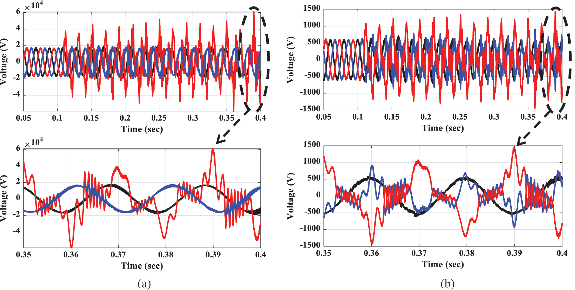
Figure 6: Ferroresonance transient overvoltage waveforms (a) Zoomed voltage waveforms at the HV side of boost transformer (Bus 2) (b) Zoomed voltage waveforms at the LV side of boost transformer (Bus 1)

Figure 7: Ferroresonance overvoltage mitigation performance using surge arrester (a) HV side voltage waveforms of boost transformer (Bus 2) (b) LV side voltage waveforms of boost transformer (Bus 1)
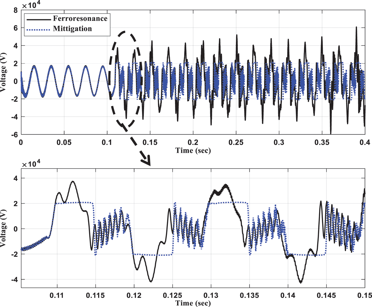
Figure 8: Ferroresonance-Overvoltage and impact of surge arrester at Bus 2
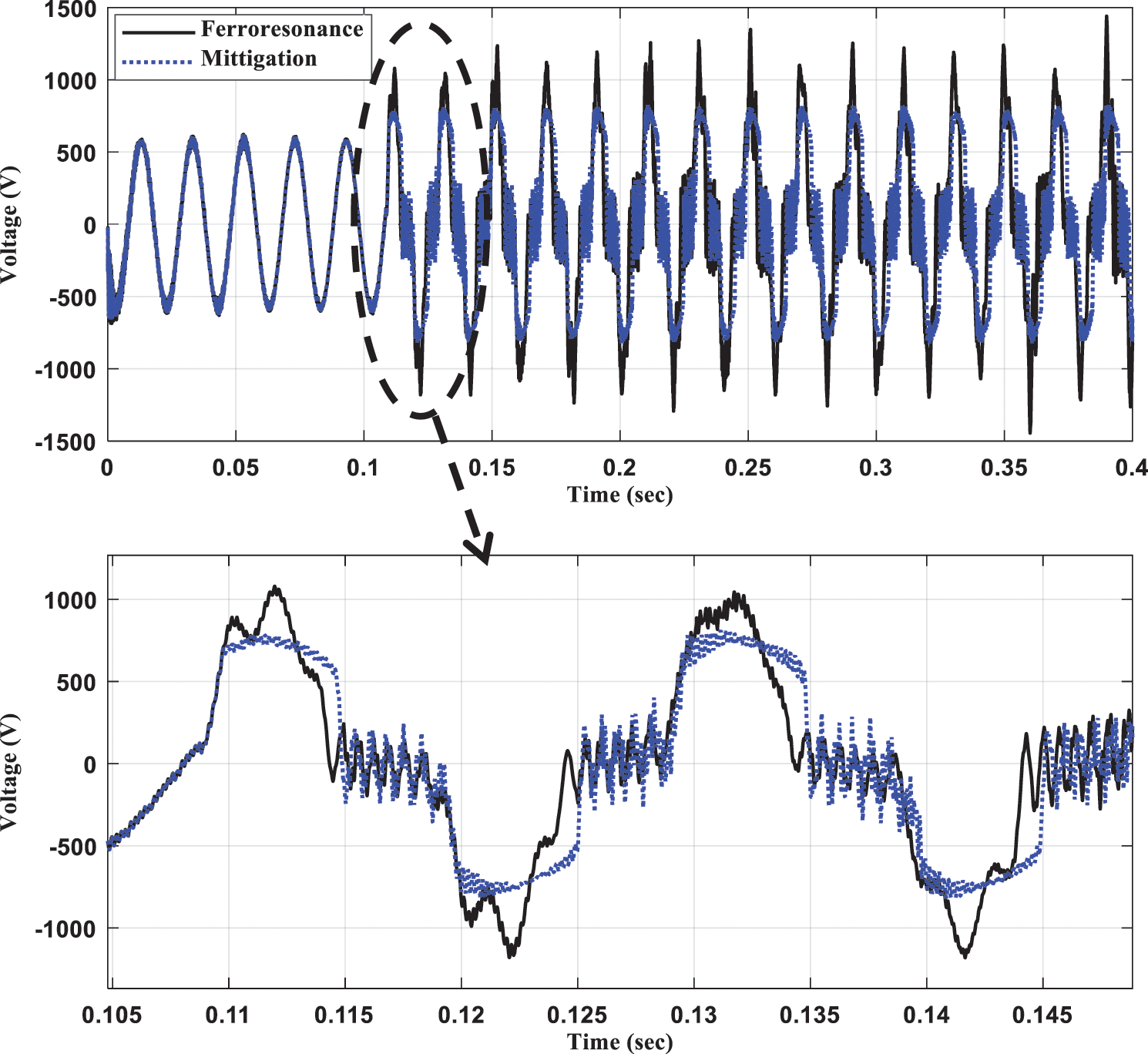
Figure 9: Ferroresonance overvoltage and impact of surge arrester at Bus 1
Fig. 10 shows the harmonic contents included in the Bus 2 and Bus 1 voltage waveforms concerning healthy (free of ferroresonance), ferroresonance, and arrester-based mitigation test cases. Tab. 1 shows the total harmonic distortion (THD) in percentage to the fundamental component of the voltage waveforms measured at Bus 2 and Bus 1. These measurements are done using the built-in function in PlotXY (a program associated with ATPDraw) and concerning the three conditions that are free of ferroresonance, ferroresonance, and mitigation. From the results in Fig. 10a, the third harmonic measured at Bus 2 is significantly found during the ferroresonance case, where its magnitude is 16.1 kV. Note that Bus 2 is in the voltage level where the ferroresonance is initiated. This value of the magnitude of the third harmonic is extremely high as it is close to the fundamental of the healthy case (16.4 kV peak value of the phase voltage). Due to the arrester interaction mitigation, the third harmonic magnitude is reduced to 4.56 kV, but it is still a high value. The fifth to sixteenth harmonic orders are significantly observed during the ferroresonance disturbance. However, their magnitudes are reduced during the arrester mitigation except that the magnitude of the fifth harmonic order is increased. Such behavior recorded at Bus 2 is reflected in the measurements at Bus 1 as depicted in Fig. 10b.
From the results summarized in Tab. 1, the THD during the healthy case (normal operation) is low, as it is 0.706% and 1.23% at Bus 2 and Bus 1, respectively. During the ferroresonance overvoltage transient period, the THD values at Bus 2 and Bus 1 are dramatically increased to 95.59% and 58.16%, respectively. They are reduced to 57.78% and 27.29% during the arrester mitigation, respectively. Although the THDs are reduced when the arresters are installed, their values are still high, and adding filters could be recommended.

Figure 10: Harmonic magnitude comparison (a) Bus 2 (b) Bus 1

Ferroresonance as an undesirable phenomenon attacking the electrical power networks was more dangerous for the recent grid-connected wind farms. This phenomenon consequently produced overvoltages as well as distorted waveforms. The ferroresonance overvoltages had been initiated using an open single-pole of the circuit breaker for a 20 kV underground cable interconnecting the wind farm with the power grid. These overvoltages had been measured at both sides of the boost power transformer. The values of the transient overvoltages have been found more than three times the rated peak value of the system-level voltage. Also, the ferroresonance overvoltage waveforms included harmonics. It was suggested to suppress these ferroresonance overvoltages using the medium voltage surge arrester installed at the high voltage side of the boost transformer. During the ferroresonance overvoltage without installing any surge arrester, harmonic contents of 95.59% and 58.16% in the voltage waveforms have been found at Bus 2 and Bus 1, respectively. These harmonics have been still existed during the arrester-based overvoltage mitigations but they were reduced to 57.78% and 27.29%, respectively. Therefore, it was recommended to design and associate a power harmonic filter with the surge arrester in order to remove these harmonics. Also, it was suggested to consider the energy dissipated by the surge arresters during the ferroresonance overvoltage mitigation as a setting for the protective relays toward avoiding the arrester burnout.
Acknowledgement: The authors would like to acknowledge the support from Taif University Researchers Supporting Project number (TURSP-2020/264), Taif University, Taif, Saudi Arabia.
Funding Statement: This study was funded from Taif University Researchers Supporting Project number (TURSP-2020/264), Taif University, Taif, Saudi Arabia.
Conflicts of Interest: The authors declare that they have no conflicts of interest to report regarding the present study.
1. U. Karaagac, J. Mahseredjian and L. Cai, “Ferroresonance conditions in wind parks,” Electric Power Systems Research, vol. 138, pp. 41–49, 2016. [Google Scholar]
2. A. Djebli, F. Aboura, L. Roubache and O. Touhami, “Impact of the eddy current in the lamination on ferroresonance stability at critical points,” International Journal of Electrical Power & Energy Systems, vol. 106, no. 2, pp. 311–319, 2019. [Google Scholar]
3. Ph. Ferracci, Ferroresonance. Cahier technique no 190, France: The Group Schneider’s, 1998. [Online]. Available: https://www.studiecd.dk/cahiers_techniques/Ferroresonance.pdf. [Google Scholar]
4. A. Akinrinde, A. Swanson and R. Tiako, “Dynamic behavior of wind turbine generator configurations during ferroresonant conditions,” Energies, vol. 12, no. 4, pp. 639, 2019. [Google Scholar]
5. A. Nassar, A.-M. Taalab, M. Izzularab and N. Elkalashy, “Investigation of resonance and ferroresonance overvoltages due to cable-transformer interactions,” ERJ. Engineering Research Journal, vol. 43, no. 4, pp. 261–271, 2020. [Google Scholar]
6. M. A. S. Masoum and E. F. Fuchs, Power Quality in Power Systems and Electrical Machines. USA: Academic Press, 2015. [Google Scholar]
7. Y. Wang, X. Liang, I. R. Pordanjani, R. Cui, A. Jafari et al., “Investigation of ferroresonance causing sustained high voltage at a de-energized 138 kV bus: A case study,” IEEE Transactions on Industry Applications, vol. 55, no. 6, pp. 5675–5686, 2019. [Google Scholar]
8. A. Ben-Tal, D. Shein and S. Zissu, “Studying ferroresonance in actual power systems by bifurcation diagram,” Electric Power Systems Research, vol. 49, no. 3, pp. 175–183, 1999. [Google Scholar]
9. S. H. Fathi and A. Abbasi, “New technique for elimination of ferroresonant oscillations in series capacitor of power system,” Asian Journal of Scientific Research, vol. 11, no. 2, pp. 203–221, 2018. [Google Scholar]
10. M. Navaei, A. A. Abdoos and M. Shahabi, “A new control unit for electronic ferroresonance suppression circuit in capacitor voltage transformers,” International Journal of Electrical Power & Energy Systems, vol. 99, no. 2, pp. 281–289, 2018. [Google Scholar]
11. M. I. Mosaad and N. A. Sabiha, “Ferroresonance overvoltage mitigation using STATCOM for grid-connected wind energy conversion systems,” Journal of Modern Power Systems and Clean Energy, Early access, pp. 1–9, 2021. [Google Scholar]
12. N. A. Sabiha and M. Lehtonen, “Lightning-induced overvoltages transmitted over distribution transformer with MV spark-gap operation—Part II: Mitigation using LV surge arrester,” IEEE Transactions on Power Delivery, vol. 25, no. 4, pp. 2565–2573, 2010. [Google Scholar]
13. N. A. Sabiha, F. Mahmood and A. M. Abd-Elhady, “Failure risk assessment of surge arrester using aralleled spark gap,” IEEE Access, vol. 8, pp. 217098–217107, 2020. [Google Scholar]
14. N. A. Sabiha, “Limiting surge arrester failure under direct lightning strokes for attaining service continuity of distribution networks,” IET Generation, Transmission & Distribution, vol. 4, no. 21, pp. 4796–4804, 2020. [Google Scholar]
15. J. R. Marti and A. C. Soudack, “Ferroresonance in power systems: Fundamental solutions,” IEE Proceedings C Generation, Transmission and Distribution, vol. 138, no. 4, pp. 321, 1991. [Google Scholar]
16. P. LaSeta, “Modeling and control of wind turbines based on doubly-fed induction generators (DFIG),” EEUG Meeting. TU Delft, The Netherlands, 2009. [Google Scholar]
17. P. Pinceti and M. Giannettoni, “A simplified model for zinc oxide surge arresters,” IEEE Transactions on Power Delivery, vol. 14, no. 2, pp. 393–398, 1999. [Google Scholar]
18. ABB Ltd, POLIM-HN, Surge Arrester. High Voltage Products, Switzerland: ABB Ltd, 2010. [Online]. Available: https://www.hitachiabbpowergrids.com/offering/product-and-system/surge-arresters/medium-voltage-surgearresters/polim-h. [Google Scholar]
 | This work is licensed under a Creative Commons Attribution 4.0 International License, which permits unrestricted use, distribution, and reproduction in any medium, provided the original work is properly cited. |