DOI:10.32604/iasc.2022.020440
| Intelligent Automation & Soft Computing DOI:10.32604/iasc.2022.020440 | |
| Article |
A Grey Wolf Optimized 15-Level Inverter Design with Confined Switching Components
1Department of ECE, St. Xavier’s Catholic College of Engineering, Nagercoil, Tamilnadu, India
2Department of EEE, St. Xavier’s Catholic College of Engineering, Nagercoil, Tamilnadu, India
*Corresponding Author: S. Caroline. Email: caroline@sxcce.edu.in
Received: 24 May 2021; Accepted: 27 June 2021
Abstract: Multilevel inverters are a new class of dc-ac converters designed for high-power medium voltage and power applications as they work at high switching frequencies and in renewable applications by avoiding stresses like dv/dt and has low harmonic distortion in their output voltage. In variable speed drives and power generation systems, the use of multilevel inverters is obligatory. To estimate the switching positions in inverter configuration with low harmonic distortion value, a fast sequential optimization algorithm has been established. For harmonic reduction in multilevel inverter design, a hybrid optimization technique combining Firefly and the Genetic algorithm was used. In several real-time systems and for solving complex engineering problems, optimization approaches are gaining popularity. Based on Grey Wolf Optimization (GWO), this research paper proposes a novel multilevel inverter architecture. The GWO algorithm is based on the natural leadership hierarchy and hunting mechanism of grey wolves (Canis lupus). The Grey Wolf Optimizer (GWO) algorithm is used to find the best switching angles for a cascaded multilevel inverter in order to eliminate some high order harmonics while sustaining the desired fundamental voltage. The proposed inverter has 15 stages, and the circuit’s unique feature includes a limited switching device. This proposed method comprises, MOSFET-based switches well as three DC sources in the main circuit. The switching parameters of the inverter topology are tuned using GWO in this methodology. The THD value of the proposed system is reduced to 6.629% compared to that of Multilevel Inverter using Genetic Algorithm, standalone power supply, Firefly assisted Genetic Algorithm, hybrid APSO algorithm, DC voltage regulation and FPGA. A few simulation studies have been included in this paper to affirm the capability of the hybrid topologies with various condition parameters, dynamic changes, and modulation indexes.
Keywords: Pulse Width Modulation; Grey Wolf Optimization; Multilevel Inverter; Total Harmonic Distortion
The multilevel inverters contribute a pivotal act accordingly in the adjustable speed drives and renewable energy generation systems. A novel 7 level inverter design was proposed in [1] and the results were associated with a classical H-bridge inverter. An asymmetrical multilevel inverter with a decreased number of switches was proposed in [2], 8 switches were utilized for the generation of 15 level inverter output. A novel cascaded multilevel inverter was proposed in [3], 11 &15 level inverter design was also proposed. The laboratory measurements reveal the performance. A novel multilevel inverter STDH-MLI (single T-type and double H-bridge multilevel inverter) was suggested in [4] for the 15 levels using three voltage DC sources. A detailed review has been conducted in [5] that highlight the different configurations of the multilevel inverter with the triggering types and its applications.
The classical cascaded multilevel inverter needs multiple DC sources and more switches, a fast recursive optimization algorithm has been established to estimate the switching positions in inverter configuration with a minimized harmonic distortion value. A thorough investigation has been conducted concerning diverse inverter topologies based on total switches, switching techniques, and control strategies. A novel multilevel inverter was designed for photovoltaic applications and the hardware implementation was also carried out using an FPGA chip. PD-PWM (Phase Disposition Pulse Width Modulation) was employed in the design of a 15-level inverter using d-space [6]. A real-time multilevel inverter analysis through Grey Wolf Optimization enables the best possible modulation with limited switching equipment. The enhancement in the power quality by diminishing the harmonic distortion in the 11-level inverter is facilitated in [7]. The genetic algorithm was deployed to determine the optimum switching angles of the switches. A hybrid optimization technique comprising of Firefly and the Genetic Algorithm was employed for the harmonic reduction in multilevel inverter design [8]. The hybrid asynchronous PSO-Newton-Raphson (APSO-NR) was utilized in [9] for harmonic reduction in the multilevel inverter design. The Selective Harmonic Elimination PWM (SHEPWM) was utilized in this work for switching the inverter topology. Regulating DC voltage supply has been used in [10]. A 3-phase 11-level cascaded H-bridge methodology multilevel inverter with diverse approaches such as teaching-learning-based optimization (TLBO), hybrid particle swarm optimization with Grey Wolf Optimization and so on, were examined in [11]. The radial basis function neural network architecture was employed in [12] for the minimization of harmonics in single DC source multilevel inverter topology. The Bee optimization algorithm was employed in [13] for the optimization of harmonics in the multilevel inverter topology. The pattern search technique was employed in [14] for the limitation of HD in the cascaded H bridge inverter. As a result, the system would be more cost efficient [15]. The asymmetrical MLI topologies were proposed to address this constraint [16]. The utilization of two-level inverter is not suited for high voltage and high power situations and to address this problem multilayer inverter is applied. Other types of inverters have lower efficiency, higher costs, and more switching losses, which encouraged this research. Furthermore, the excellent efficiency and low switching losses of the 15-level multilayer inverter are driving this research. The major contribution of this research work is categorized into three. The first part deals with parameter tuning of GWO, the second part includes the operation of GWO and the final step includes the harmonic reduction of the multilevel inverter through GWO. The subsequent Section 2 describes the materials and methods of the research.
2.1 Multilevel Inverter with Parameter Tuning by Grey Wolf Optimization
The proposed research work focuses on the design of the multilevel inverter with the limited power electronic switches. The 15 level inverter design was anticipated in this research and the basic functional diagram of 15 level inverter is shown in Fig. 1. A single H bridge inverter is used in this research work and MOSFET switches are used. The input to the H bridge inverter is fed by a circuit comprising of 3 MOSFET switches with freewheeling diodes and capacitors.

Figure 1: Proposed 15 level inverter topology
In the proposed model, two circuits are there; the level circuit (1) and the polarity circuit (2). The level circuit comprises of three switches (S1, S2 and S3) that generate 15 level step waveform output and the polarity circuit utilizes four switches (S4, S5, S6 and S7) that generate a bipolar output voltage. The switches S4 and S5 generate positive polarity output voltage, while the switches S6 and S7 generate a negative polarity output voltage. The three DC voltage sources used in this work can generate 15 levels of output voltages (7, 6, 5, 4, 3, 2, 1, 0, –1, –2, –3, –4, –5, –6 and –7 V).
The H bridge inverter circuit is depicted in Fig. 4. A single H bridge inverter is used in this research work and MOSFET switches are used. A parallel combination of a diode and a capacitor is connected in shunt across the three switches. The multilevel carrier pulse width modulation scheme is employed in this work. The sinusoidal waveform is the source signal and the triangular waveform is the carrier signal. The multiple carrier signals relies on the configuration of the inverter topology. The carrier waveform is compared with the source signal continuously and while carrier signal amplitude is smaller than the reference point, the corresponding control is turned on. Each carrier signal is related to one switch in the circuit.
Let the amplitude and frequency of the sinusoidal and reference signal be Aref and fref respectively. The values of the AMI (amplitude modulation index) and the FMI (frequency modulation index) is represented as follows.
The GWO (Grey Wolf Optimization) algorithm is employed in this work to estimate the optimum switch angles of the switches. The objective of the inclusion of the optimization technique is to limit the HD in the inverter output voltage. The GWO is a bio-inspired optimization algorithm formulated from the biological traits of Grey Wolf (Canis Lupus, which belongs to Canidae biological family). In the food chain structure, it holds the top position. They usually live in a group and the flock size is 5–12. Within the grey wolves family itself, different classifications are there. They follow a strict dominant hierarchy.
Alphas: The alphas (α) group are leaders and they may be of any gender. The obligation for making decisions regarding hunting sleeping and other duties relies on them. The decisions taken by the alphas are delivered to the lower classes. They are considered the most dominant ones since their orders matting takes place within the alphas themselves. The count of alphas is low in number in the hierarchy and they have the leadership skill in managing the entire group.
Betas: The next level of wolves in the hierarchy are betas and they assist alphas in the process of making decisions. The beta wolf also includes either gender and in case, if an alpha wolf is dead, it will get an opportunity to become the leader. In general, beta wolves respect alphas and monitor, control subordinates. The beta wolves implement the rules of alphas and provide feedback to the alpha.
Deltas: Delta wolves serve alphas and betas but they control omegas. The different category of delta wolves are as follows; Scouts: They watch the boundary and in the case of any danger, they generate the signal, Sentinals: They are called security of the group, Huntsmen: They help alphas and betas in chasing for food, Caretakers: They are responsible for the caring of the week and ill wolves.
The mathematical formulation of the GWO is as follows
Social Hierarchy: While solving a problem using Grey Wolf Optimization, Social Hierarchy of the wolves is vital. The best optimum solution is alpha (α), the 2nd and the 3rd. The optimal solutions are referred to as beta ( ) and delta ( ). The equilibrium solutions are ω. The hunting (Optimization) was performed by the Omega (ω) wolves as follows by these three wolves.
Encircling Prey: The GW endure throughout the act of hunt. Mathematically; the enfolding behaviour is represented as follows
where
The coefficient vectors are calculated and expressed in the following manner.
Through the loops, the components decrease linearly from 2 to 0. The random vectors r1 and r2 are identified in the set [0,1].
Hunting: GW (Grey Wolves) can identify the prey and encircle them. In hunting, alpha and beta wolves mainly participate and deltas rarely participate. According to the search agent (SA), we select the perspective of the best search agent by the three optimal solutions. The equations are as follows:
Attacking Prey: When it stops moving, it finishes the hunt by attacking the prey. By the mathematical method,
The pseudocode of the GWO algorithm is as follows.
Initialization of GW population Gi(i = 1, 2, 3,…, n)
Determine a, A and C
Estimate the fitness of every SA
While (t < max number of iteration)
For every SA
Update the location of the present SA end for
Update a, A and C
Evaluate the fitness of all SA
Update the values of
t = t + 1
End while
Return
The flow chart of the GWO is depicted in Fig. 2.

Figure 2: Flow chart of the GWO
2.3 Harmonic Reduction in the Multilevel Inverter by GWO
The expression for the total harmonic distortion (THD) is as follows.
From the expression, it is clear that to minimize the THD, the quantity of lower-order harmonics have to be eradicated. Consider the case of an 11 level inverter, the third, fifth, seven and ninth order harmonics are eliminated as follows;
For the elimination of harmonics, the classical method employed is the Newton Raphson Method [17] and the Genetic algorithm [18] is also widely used in many inverter topologies. In the proposed research work, Grey Wolf Optimization was employed for the optimum selection of switching phase present in the inverter topology. The manual tuning of switching phase was replaced by the automatic tuning by Grey Wolf Optimization algorithm.
The following Section 3 emphasizes the Simulink findings and review of the intended work.
The algorithms are developed in MATLAB 2019a and the script code, Simulink model was used. The GWO was written in script code and the optimum values of the switching angles are passed to the Simulink model. The 15-level inverter Simulink model (main block) is demonstrated in Fig. 3.

Figure 3: Simulink model of 15 level inverter (main block)
To estimate the optimum switching angles of the inverter circuit, optimization algorithms play a pivotal role. Fig. 4 shows the H bridge inverter topology. The number of training samples (Grey Wolves) and iterations are modified, and the switching angles are determined. The global best position of the GWO estimates the optimum value of switching angles. The MLPWM Simulink circuit is shown in Fig. 5.

Figure 4: H bridge inverter topology

Figure 5: MLPWM simulink circuit
The number of iteration was changed from 30 to 100 and the results are depicted in Tabs. 1–4. Tab. 1 depicts the best solution obtained by GWO for the various number of iterations. Multilevel inverters with redundant switching however, includes switching losses due to the high-frequency switching so fewer possible switching is preferred over the existing techniques.


Tab. 2 depicts the best optimal solution obtained by GWO for various SA.
Tab. 3 depicts the MLPWM parameters for various iteration count of GWO algorithm.
Fig. 6 illustrates the simulation outcome of 15 level inverter input and output waveform corresponding to the number of iterations = 30 and its corresponding spectrum analyzer output is shown in Fig. 7. Switching pulses for main block circuit is depicted in Fig. 8.

Figure 6: 15 level inverter input and output waveform corresponding to the number of iterations = 30

Figure 7: Spectrum analyzer output corresponding to the output voltage corresponding to the number of iterations = 30

Figure 8: Switching pulses for main block circuit
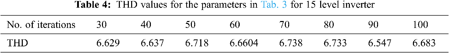
Tab. 4 depicts the THD values for the parameters in Tab. 3 for 15 level inverter. Tab. 4 results reveal that with the increase in iteration values also, there is not much significant change in the THD value. The iteration value of N = 30 is appropriate for this research work.
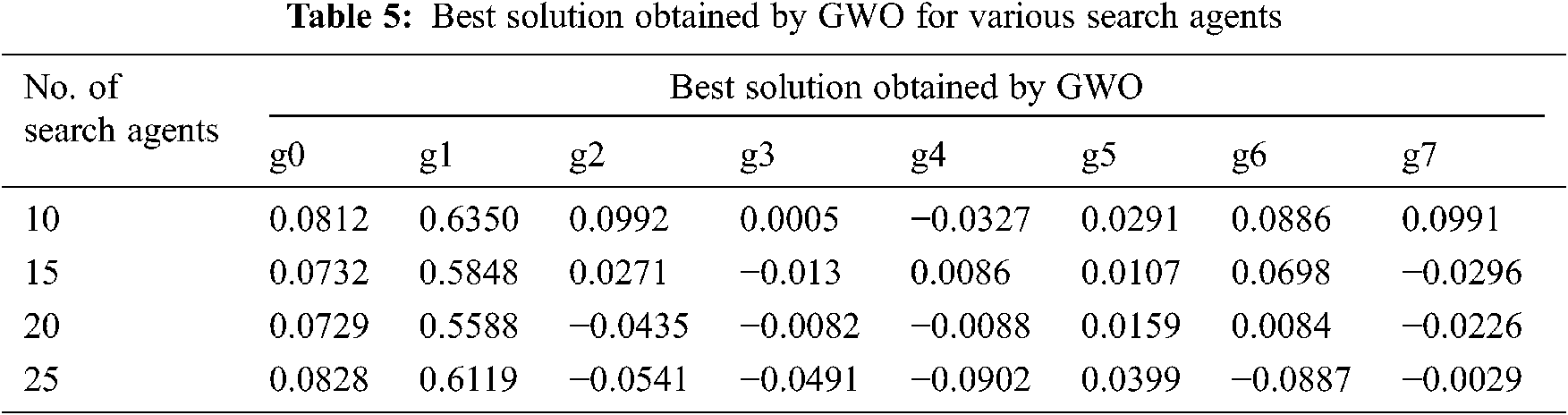
The number of SA was changed from 10 to 30 with an increment value of 5 and the results are depicted in Tabs. 5–8. Tab. 5 depicts the best solution obtained by GWO for the various number of iterations. Fig. 9 shows a 15 level inverter input and output waveform corresponding to SA = 10 and number of iterations = 50 and its corresponding Spectrum analyzer output is shown in Fig. 10.

Figure 9: 15 level inverter input and output waveform corresponding to SA = 10 and number of iterations = 50

Figure 10: Spectrum analyzer output corresponding to SA = 10 and number of iterations = 50
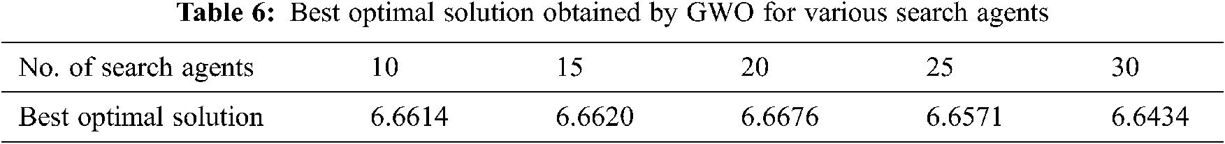
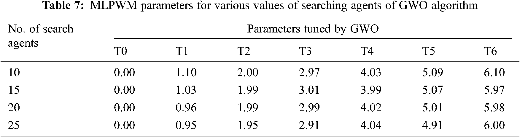
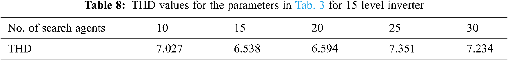
Tab. 6 depicts the best optimal solution obtained by GWO for various SA. Tab. 7 depicts the MLPWM parameters for various iteration count of GWO algorithm. Tab. 8 depicts the THD values for the parameters in Tab. 3 for 15 level inverter.
Fig. 9 shows a 15 level inverter input and output waveform corresponding to SA = 10 and number of iterations = 50 and its corresponding Spectrum analyzer output is shown in Fig. 10.
Fig. 11 shows the GWO plot for Number of cycle = 30, the total SA = 10 and Number of SA = 10 and number of cycles = 50.

Figuer 11: GWO plot for the two cases (a) Number of cycles = 30 and number of SA = 10, (b) Number of SA = 10 and the number of cycles = 50
The hardware structure shown in Fig. 12 is comprised of two Arduino controllers, one of which is connected to the PWM and the other of which regulates and tracks the heat sink temperature and enables the pulse to the PWM circuit to power the EC fans. Besides, the Arduino controller generates PWM pulses and delivers them to the driver board as input and confers it to a 15 level inverter circuit. Using the DC fans, the Arduino controller regulates the temperature. The driver transformer imparts the power supply of driver boards. Driver board is primarily used to reinforce isolation and amplification. The lamp loads and power supply are attached to these boards. The further step incorporates the monitoring and controlling of the temperature and the induced PW pulse is sent to the MOSFET module. In the MOSFET module, the 12 Volt DC voltage is transformed from AC to DC by means of a bridge rectifier and filter in the transformer. The two DC fans are powered by a 12 Volt DC supply. The PWM is routed via a MOSFET IRP40, which controls the speed of the DC fans. It is made up of a power circuit transformer that supplies power to the driver circuit.

Figure 12: Hardware structure of 15 level inverter
The Arduino controller is interfaced with the computer which works with a serial monitor which displays all nine heat sink temperatures as the differential-based DC fans spin. The average temperature is between 20 and 30 degrees. The heat sink temperature, PWM, and fan speed increase when the power supply is turned on.
In the digital storage oscilloscope (DSO), the signal of the 15 stage inverter is obtained, and the lamp load glows.
The Fig. 13 represents the DSO output of 15 level inverter. Heat sink temperature is monitored in serial monitor, where any variation in the heat sink varies the speed of the DC fan.

Figure 13: DSO output of 15 level inverter
Tab. 9 results reveal that with the change in the number of SA also, there is a considerable change in the number of SA also, there is a considerable change in the THD value. The optimum value of the total SA is observed to be 15. For comparative analysis, the following works are considered and the results are depicted in Tab. 9. The comparative study of the proposed novel multilevel inverter topology was made by comparing with the existing works and the results show the proficiency of the approach.
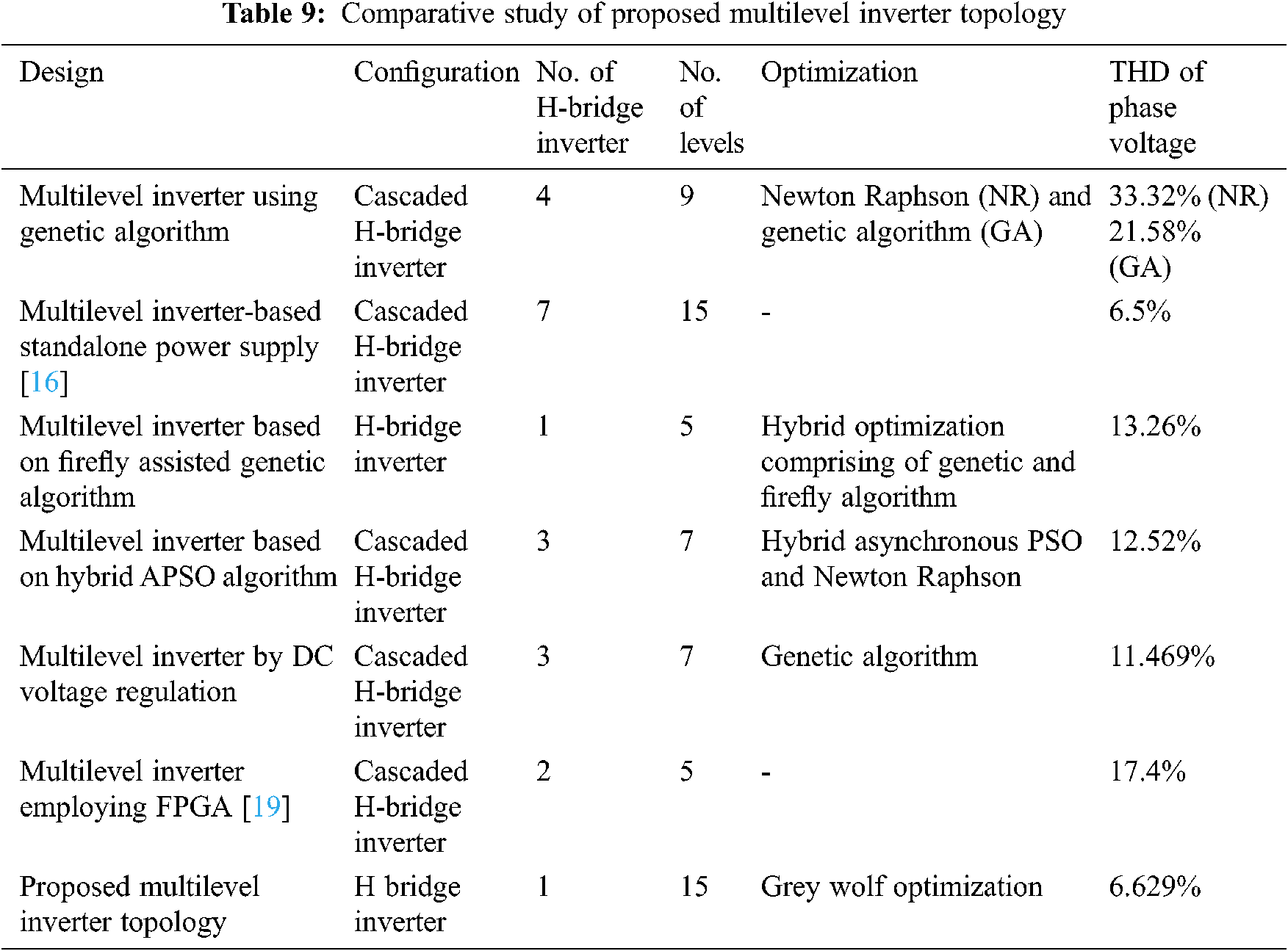
The 15 level inverter in Fig. 14 is the proposed novel multilevel inverter design based on the GWO. The THD value of the novel 15 level inverter design was found to be low associated with the other multi level inverter topologies.

Figure 14: Comparative analysis of THD values of multilevel inverter design based on MOSFET switches
The subsequent Section 4 illustrates the conclusion of the research work.
This research work proposes a novel multilevel inverter scheme design for 15 levels based on GWO. The manual tuning of parameters in the classical design was replaced by GWO. The proficient results are produced for the GWO based parameter tuning in multilevel inverter design with an optimum THD value of 6.629. The parameter tuning in GWO is simple and hence that makes an attractive solution to this research work for optimization technique when compared with the classical optimization techniques. The outcome of this research work can be used for applications in electric drives as well as for renewable power generation systems.
Further improvement in the research work can be done by supplementary levels of inverters in future work.
• The script code, Simulink model was used in Fig. 3.
• Comparative study of proposed multilevel inverter topology in Tab. 9.
Acknowledgement: The author with a deep sense of gratitude would thank the supervisor for his guidance and constant support rendered during this research.
Funding Statement: The authors received no specific funding for this study.
Conflicts of Interest: The authors declare that they have no conflicts of interest to report regarding the present study.
1. E. Beser, S. Camur, B. Arifoglu and E. K. Beser, “Design and application of a novel structure and topology for multilevel inverter,” in Proc. Int. Symposium on Power Electronics, Electrical Drives, Automation and Motion, Ischia, Italy, pp. 969–974, 2008. [Google Scholar]
2. Z. Salam, A. Majed and A. M. Amjad, “Design and implementation of 15-level cascaded multi-level voltage source inverter with harmonics elimination pulse-width modulation using differential evolution method,” IET Power Electronics, vol. 8, no. 9, pp. 1740–1748, 2015. [Google Scholar]
3. K. Corzine and Y. Familiant, “A new cascaded multilevel H-bridge drive,” IEEE Transactions on Power Electronics, vol. 7, no. 1, pp. 125–131, 2002. [Google Scholar]
4. M. Rawa, M. D. Siddique, S. Mekhilef, N. Mohamed Shah, H. Bassi et al., “Design and implementation of a hybrid single T-type double H-bridge multilevel inverter (STDH-MLI) topology,” Energies, vol. 12, no. 9, pp. 1–15, 2019. [Google Scholar]
5. S. P. Sunddararaj, S. Rangarajan and N. Subashini, “An extensive review of multilevel inverters based on their multifaceted structural configuration, triggering methods and applications,” Electronics, vol. 9, no. 3, pp. 1–33, 2020. [Google Scholar]
6. S. Mukherjee, S. De, S. Sanyal, S. Das and S. Saha, “A 15-level asymmetric H-bridge multilevel inverter using d-SPACE with PDPWM technique,” International Journal of Engineering, Science and Technology, vol. 11, no. 1, pp. 22–32, 2019. [Google Scholar]
7. M. Perumal and D. Nanjudapan, “Performance enhancement of embedded system based multilevel inverter using genetic algorithm,” Journal of Electrical Engineering, vol. 62, no. 4, pp. 190–198, 2011. [Google Scholar]
8. M. A. Memon, S. Mekhilef and M. Mubin, “Selective harmonic elimination in multilevel inverter using hybrid APSO algorithm,” IET Power Electronics, vol. 11, no. 10, pp. 1673–1680, 2018. [Google Scholar]
9. N. Farokhnia, S. H. Fathi, N. Yousefpoor and M. K. Bakhshizadeh, “Minimisation of total harmonic distortion in a cascaded multilevel inverter by regulating voltages of DC sources,” IET Power Electronics, vol. 5, no. 1, pp. 106–114, 2012. [Google Scholar]
10. D. Falehi, “Novel harmonic elimination strategy based on multi-objective grey wolf optimizer to ameliorate voltage quality of odd-nary multi-level structure,” Heliyon, vol. 6, no. 3, pp. 3585, 2020. [Google Scholar]
11. N. Riad, W. Anis, A. Elkassas and A. E. W. Hassan, “Three-phase multilevel inverter using selective harmonic elimination with marine predator algorithm,” Electronics, vol. 10, no. 4, pp. 374, 2021. [Google Scholar]
12. A. Kavousi, B. Vahidi, R. Salehi, M. K. Bakhshizadeh, N. Farokhnia et al., “Application of the bee algorithm for selective harmonic elimination strategy in multilevel inverters,” IEEE Transactions on Power Electronics, vol. 27, no. 4, pp. 1689–1696, 2012. [Google Scholar]
13. N. Suresh and S. R. Babu, “Reduction of total harmonic distortion in cascaded H-bridge inverter by pattern search technique,” International Journal of Electrical & Computer Engineering, vol. 7, no. 6, pp. 3292–3298, 2017. [Google Scholar]
14. Y. Liu, H. Hong and A. Q. Huang, “Real-time calculation of switching angles minimizing THD for multilevel inverters with step modulation,” IEEE Transactions on Industrial Electronics, vol. 56, no. 2, pp. 285–293, 2009. [Google Scholar]
15. N. Yousefpoor, N. H. Fathi, N. Farokhnia and N. A. Abyaneh, “THD minimization applied directly on the lline-to-line voltage of multilevel inverters,” IEEE Transactions on Industrial Electronics, vol. 59, no. 1, pp. 373–380, 2012. [Google Scholar]
16. R. Beig and A. Dekka, “Experimental verification of multilevel inverter-based standalone power supply for low-voltage and low-power applications,” IET Power Electronics, vol. 5, no. 6, pp. 635–43, 2012. [Google Scholar]
17. T. Porselvi, K. Deepa and R. Muthu, “FPGA based selective harmonic elimination technique for multilevel inverter,” International Journal of Power Electronics and Drive Systems, vol. 9, no. 1, pp. 166–173, 2018. [Google Scholar]
18. A. Farakhor, R. R. Ahrabi, H. Ardi and S. N. Ravadanegh, “Symmetric and asymmetric transformer based cascaded multilevel inverter with minimum number of components,” IET Power Electronics, vol. 8, no. 6, pp. 1052–1060, 2015. [Google Scholar]
19. A. Hassan, X. W. Yang Chen and M. A. Houran, “A state of the art of the multilevel inverters with reduced count components,” Electronics, vol. 9, no. 11, pp. 1924, 2020. [Google Scholar]
 | This work is licensed under a Creative Commons Attribution 4.0 International License, which permits unrestricted use, distribution, and reproduction in any medium, provided the original work is properly cited. |