DOI:10.32604/iasc.2022.020649
| Intelligent Automation & Soft Computing DOI:10.32604/iasc.2022.020649 | |
| Article |
Low Cost Autonomous Learning and Advising Smart Home Automation System
Department of Automation, Technical University of Cluj Napoca, Cluj Napoca, 400114, Romania
*Corresponding Author: Daniel Chioran. Email: daniel.chioran@aut.utcluj.ro
Received: 01 June 2021; Accepted: 22 July 2021
Abstract: In today’s world, more than ever before, we are fascinated and drawn towards smart autonomous devices that make our lives safer and more comfortable. Devices that aid in reducing our energy consumption are also highly appreciated but often quite expensive to buy. This context is favorable for developing an autonomous smart home automation system (SHAS) with energy-saving potential and low price, making it widely accessible. This paper presents the design and prototype implementation of such a low-cost micro-controller based autonomous SHAS that learns the resident’s work schedule and integrates a wide array of sensors and actuators to automatically control the lights, temperature, humidity and power sockets. The proposed automation system also monitors the home environment for potential energy-saving opportunities, gas leaks, or unauthorized entry. For reliability purposes and to limit the risk of signal interference, the proposed system design uses a wired inter-module communication method. To enhance the home’s security, both personal identification number (PIN) protection and Global System for Mobile Communications (GSM) communication are added, making the proposed system design less vulnerable to cyber-attacks when compared to other wireless alternatives. The hardware and software architectures, the prototype test results and the cost analysis are presented in detail, validating the system’s design and efficient operation as an autonomous smart home automation system.
Keywords: Home automation; micro-controller; autonomous devices; GSM communication; energy consumption
Aiming to improve our safety and quality of life, automation systems found their way into our homes for several years now. They usually link different appliances and electronic devices to a central hub where information from sensors is received and analyzed, making it possible to implement control functions for light sources, room temperature, air humidity and home security (naming only a few). By integrating new technologies and intelligent control algorithms, smart home automation systems have the potential to improve home security, safety and comfort while also reducing the home’s energy consumption if energy management functions are integrated into the system.
In recent years, an impressive growth in the home automation market has been observed as people wish to enjoy a comfortable, safe and secure home and SHAS promise to ensure exactly that. The online statistics portal Statista [1] estimates that in 2020 there were over 40 million smart homes in the United States of America, with a market valued of USD 24.9 billion, an annual growth of 18.3% and a forecast to reach USD 41.3 billion by the year 2023. The “Smart Homes and Home Automation 7th Edition” report [2] for the European and North American markets combined estimates an annual home automation market growth rate of 19.8%, reaching a value of USD 90.6 billion by the year 2023.
Smart home automation systems often have built-in functions that reduce the overall energy consumption in a home by implementing intelligent control techniques and efficient energy management. This helps protect the environment, a topic of great importance in the context of the world’s growing energy demand and ongoing global warming. The available statistic data shows that about 40% of the energy consumption of the United States of America was recorded in residential buildings in the year 2017 [3] while, according to Eurostat [4], during the same year, European residential buildings recorded around 27% of continent’s energy consumption. These values are significant, so new technologies that have the potential to reduce our home energy consumption are highly relevant in today’s world.
A relevant fact in 2021 and one that might influence how new SHAS are developed is the recent global pandemic of corona virus disease and its associated economic recession. People still have a natural desire to improve their quality of life, however their income was affected and their purchase power decreased. Most current SHAS are expensive to buy, so new designs should be efficient yet inexpensive in order to be appealing to more low-income buyers. In this context, one of the most affordable SHAS was designed, built and tested, with this paper presenting the laboratory test results.
Smart home automation systems are rapidly gaining popularity, with numerous designs and configurations being proposed by researchers and manufacturers. Currently, we see a fragmented market without internationally agreed standards regarding these systems. Even so, many SHAS can already be purchased and millions are already installed. Several SHAS proposed by researchers (mainly those built around Arduino development boards) are discussed next. Our own design will then be presented.
During the literature review it was observed that some home automation systems, as those seen in References [5–7] simply allow the users to control different aspects of their homes from one single interface, usually a mobile app or a web-based graphical user interface (GUI). In such cases, the system itself does not act independently, making it a hub for centralized home control. More advanced systems are designed to have various degrees of autonomy, acting in response to sensor input without constant user intervention. In these systems, data is received from the connected sensors (e.g., temperature, light intensity, smoke and gas or proximity sensors) and used to formulate commands according to the control software that runs the system. Naing et al. [8] provide such an example where the temperature, light intensity and motion sensors are used to automatically control a cooling fan, the lights and door buzzer. With a slightly different array of sensors, the automation system presented by Peter et al. [9] collects environmental data and sends it to an Arduino Uno which commands relays that in turn control home appliances. The design of a SHAS based on a wireless sensor network is presented by Song [10], incorporating water, electricity, gas and heat meter data acquisition and control.
In addition to providing monitoring and control functions as the systems presented above do, more complex designs incorporate energy management control and power saving functions as discussed by Hsu et al. [11] where the user’s location inside the home environment is analyzed for this purpose. Collotta et al. [12] propose a solution based on user feedback and fuzzy logic controller for smart energy management, while Hu et al. [13] show how machine learning is integrated in the design of a smart home energy management system to increase its efficiency.
With numerous sensors, actuators and powerful controllers, the complex SHAS designs are often highly efficient in performing automation and control functions in the home environment. However, their complexity is often associated with a higher initial purchase price. Similar to the above complex systems, our proposed design is also autonomous and incorporates energy management functions meant to reduce the home’s energy consumption. The proposed SHAS design has an affordable price as it uses an inexpensive Arduino Uno development board together with compatible sensor and relay modules. Low purchase prices and easy programming make the Arduino platform a popular choice in home automation systems, with the Uno board being used in [5–6,9], the Nano in [8] and the Mega board in Reference [11]. For various reasons (e.g., built-in Ethernet connectors or larger memory size) alternative microcontrollers were sometimes used. Santhoshsivan et al. [7] used the NodeMCU (ESP8266) controller, Song [10] chose the 16-bit 80C196KC controller and Manda et al. [14] used the ARM NXP LPC11U24.
For user – system interaction, multiple solutions are identified. Using mobile phone apps as graphical user interfaces is the most popular approach to display sensor data and to control different home functions or appliances. This is associated with the use of Bluetooth technology in [5,6] and Wi-Fi in [7,9]. The wireless interaction between user and automation system is also possible through voice commands as shown by Peter et al. [9] or through 3D gestures as demonstrated by Hsu et al. [11]. The use of GSM technology is preferred in some systems, such seen in [8,14] but is mostly associated with the safety and security functions as users receive notifications on their mobile phones when certain events (door/window opened; motion, fire or gas detected) trigger an alarm.
Wireless communication methods are sometimes utilized to connect system components to each other, linking sensor modules to the control hub via Bluetooth as shown by Collotta et al. [12] or via Zigbee and Wi-Fi as shown by Hu et al. [13]. Wi-Fi is preferred in Internet of Things (IoT) based home automation networks, where smart appliances and IoT devices use this technology to connect to the internet. One of the main reasons for choosing wireless communication technologies is the convenience and ease of installation however, designs that heavily rely on the network environment to communicate might be affected and their performance might be limited by the lack of constant or stable internet access. The alternative is a wired communication solution as shown by Song [10] where power line communication is preferred or in References [5–6,8,9,11] where similar to our proposed design, a simple wired link between controller and modules is utilized. This last solution is less prone to interference when compared to wireless alternatives but is more difficult to install, requiring extra time and labor. The following SHAS design was proposed after a careful analysis of the references presented above, aiming to incorporate as many functions as possible into the new SHAS design while keeping the system’s purchase price low.
The Arduino Uno microcontroller board is chosen as the control hub of this SHAS while a selection of affordable sensors and relays ensure the data acquisition and control functions. This development board is easily programmable using the C/C++ programing language, it has sufficient processing power to run the control software and being open source, it is affordable with multiple clones and alternatives easily available. Figs. 1a and 1b present the block and wiring diagrams of the selected components. In addition to sensors and relays, the system’s wall mounted terminal includes a local liquid crystal display (LCD) and numeric keypad. Once configured, this SHAS can operate independently, without further user input. Because internet connected devices are known to be vulnerable to online cyber-attacks with hackers often gaining unauthorized access to IoT devices, some users are understandably concerned about their privacy and about other people accessing their SHAS over the internet without permission. Our proposed SHAS design answers these concerns by operating locally/independently and by using GSM instead of internet communication to implement long-distance system control and notification functions.

Figure 1: (a) The SHAS block diagram (b) the SHAS wiring diagram
System components were carefully chosen because of the limited number of general purpose input output (GPIO) pins available on the development board (20 pins) and because some of these pins are reserved for inter-board communication purposes. Such examples are the serial data line (SDA) and serial clock line (SCL) pins reserved for inter-integrated circuit (I2C) communications or the transmitting (TX) and receiving (RX) pins for the universal asynchronous receiver-transmitter communication (UART). Some sensors require a specific type of pin (digital or analog) to be connected to and the power consumption of all connected modules must be considered as GPIO pins can be easily damaged by over-loads. As the GSM module alone can require up to 2A at maximum consumption, this module is powered by a dedicated auxiliary power source, while other modules are powered directly from the Arduino Uno board using the 5 V and ground (GND) pins. Using GPIO pins to power modules is not a viable solution, as the maximum current drawn via these pins should not exceed 200 mA in total or 40 mA per pin.
On average, heating accounts for 64.1% [4] of the total energy consumed in European homes. An efficient way to reduce the energy consumption of a home is by implementing efficient temperature control based on accurate measurements and home occupancy data. Temperature measurements are performed by two DHT11 thermistor based modules, one for outside and one for inside measurements. These modules can also measure the air humidity level, allowing the system to record and control this parameter as well. The HC-SR501 passive infrared pyro electric motion detection sensor module detects the movement of subjects in its vicinity. Three of these modules are placed inside the house and the information they provide is used by the SHAS for three purposes: firstly to control the lights and the connected appliances in response to the user’s movement (or lack of movement); secondly to learn the user’s daily work schedule, so it can better control the home’s heating; thirdly to detect unauthorized entry inside the house. For safety related functions, the system incorporates a MQ-2 module to detect gas leaks (methane, propane, isobutene) or smoke build-up. This component is extremely sensitive and able to detect gases in concentrations as low as 10 ppm or 0.0001%. A light intensity module built around a light dependent resistor (LDR) is used to detect the exterior ambient brightness or light intensity. This information is used by the SHAS when the automatic light control is activated and movement is detected inside the house. Six relay modules are placed between the controller’s digital output pins and the connected systems and devices. Each relay is controlled using a 5 V direct current, while the relay module itself can handle up to 250 V alternative current on its high voltage terminal.
The active buzzer module is used to alert the tenants in case of a gas leak. It can also be used as a wake-up alarm, a reminder or to signal that a certain condition has been verified. This compact module produces a 2 kHz sound without using an external frequency generator. A small analog numeric keypad allows the user to navigate through the SHAS menus and modify the timers and set-points. The LCD module integrated into the system’s architecture can display menus, sensor data or notifications. The display can accommodate 32 characters on two rows and has an I2C serial interface adapter, so it connects to the controller using only two data and two power lines. A SIM800 GSM module is connected to the controller in order to facilitate long distance communication. The user is notified by the SHAS if there is an alarm triggered at home. The user can also send commands to the system via text messages. An UART communication is established between the GSM module and the controller using the D0 (RX) and D1 (TX) digital pins. Power to the module is provided by an auxiliary power supply. The highly popular Arduino Uno development board is used to run the control software in this SHAS design. It has an ATmega328P-16 MHz micro-controller, a 32 kb flash memory to store the C/C++ control software, a 2 kb static random access memory (SRAM) for dynamic variables and a 1 kb electrically erasable programmable read-only memory (EEPROM) used to store system configuration data. There are 20 GPIO pins available and dedicated ones for I2C communication and power supply.
Arduino integrated development environment (IDE) is used to program the microcontroller. The C/C++ code is called a “sketch” and it is uploaded to the controller’s 32 kb flash memory via an external programmer as the D0 and D1 pins are used for the GSM communication. When the controller is powered, it automatically runs the sketch. First executed (once on every startup) is the “setup ()” function where the variables, the serial communication and the LCD are initialized. The EEPROM memory is also accessed at this point to retrieve the parameters it stores. The “loop ()” function contains the main control logic and it is executed repeatedly (as its name suggests) as long as the system is powered. Fig. 2 shows the flow diagram of this control logic. Several particularities of the control software will be discussed next.
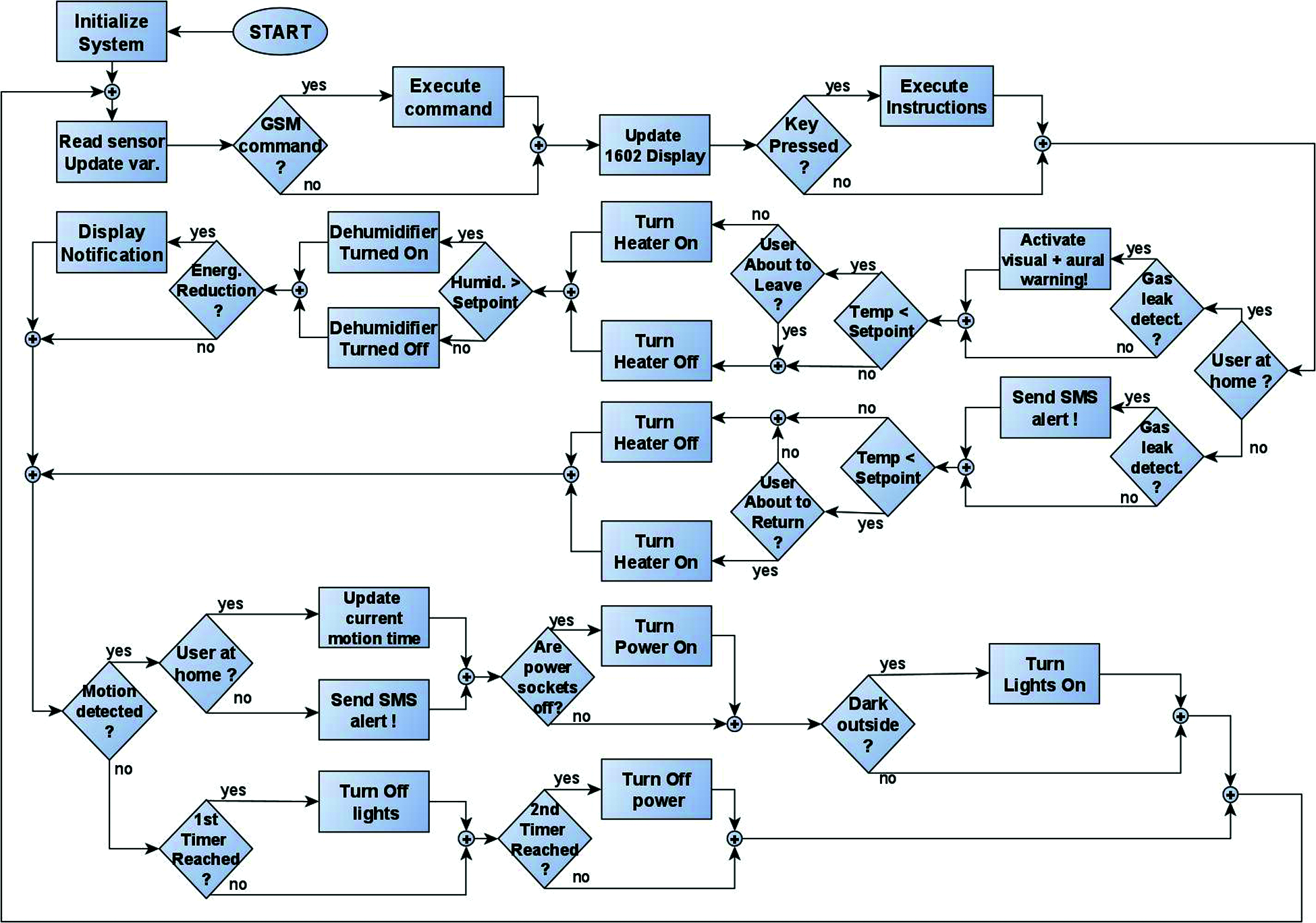
Figure 2: The flow diagram of the C/C++ control software
Each DHT11 temperature and humidity module communicates with the controller via a single digital pin and provides both temperature and humidity measurements. The “dht.h” library is included into the sketch, as it contains the functions needed to interact with the DHT11 modules. The “Wire.h” library handles the I2C communication between the controller and the LCD, while the “LiguidCristal_I2C” library contains functions specific to the LCD operation. The I2C serial protocol uses only two wires to transfer data, and these are connected to dedicated pins on the Arduino board. As a result, more GPIO pins are available for connecting sensors and actuators. The LCD and the numeric keypad allow the user to set up the SHAS, selecting specific values for the desired room temperature, humidity level, light intensity set point (for lights control) and the timer values (for lights and power switch control). It is essential that these values are stored in the controller’s 1 kb EEPROM memory and automatically restored after a system reset. The “EEPROM.h” library is included into the sketch for this purpose. The EEPROM memory holds 1024 byte variables and has a limit of around 100000 write cycles. To protect it against unnecessary write operations, the “EEPROM.update(address, value)” command is used. This command rewrites the memory only if the included value differs from the one already stored at that address.
The “RTClib.h” library allows the controller to communicate with the real time clock (RTC) module and access the current time and date. This information is used to control the home’s heating based on the user’s work schedule, and to control the lights or the power sockets based on the time-stamp of the last motion detection. Timers are used to control how frequent are notifications displayed on the LCD. The last library included into the sketch is “sms.h”. It provides methods for sending and receiving text messages, making the long distance GSM communication with the SHAS possible.
The main novelty feature that differentiates this proposed SHAS from most others is its ability to learn the user’s work schedule and to gradually (and autonomously) adapt to it when changes are detected. This feature is useful when controlling the home’s heating system, as the effect of starting/stopping the heater is felt only after a certain period, not instantaneous as in the case of controlling electronic devices (radio, lights). More powerful and expensive SHAS designs implement neural networks and machine learning to achieve the same behavior, but this is not a viable solution for a low-cost system with limited memory and processing power such as the one we propose. A simple solution was needed and was developed using a statistical method based on weighted averages. This simplified learning solution is implemented by our proposed SHAS. The system detects the user’s movement (or lack of movement) inside the house and automatically calculates a set of weighted averages for the user’s departure and return times. For each day of the week, these averages and their associated weights are saved in the EEPROM memory. It is unnecessary to heat the house shortly before the resident usually leaves. The energy consumed by doing so is wasted as the user doesn't benefit from the generated heat, so this SHAS is programmed not to heat the house when the user is expected to leave within the next 30 min. In contrast, the SHAS will heat the house 30 min before the resident’s usual return time.
Eq. (1) is used to calculate the weighted averages and it is explained as follows: WAnew is the new weighted average, WAold is the old one, Nt is the newest time-stamp added to the average and Tw is the current weight. By comparing the current time with these calculated weighted averages, the SHAS can deduce that the user’s departure or return is imminent and control the home’s heating accordingly.
4 Prototype Construction and the Evaluation Method
A prototype was built and laboratory-tested to validate the proposed SHAS design. The hardware components were connected according to the wiring diagram presented in Fig. 1b and the C/C++ code was uploaded to the controller. Next, the prototype was configured by entering the desired values for the timers and for the controlled parameters. As an example, Fig. 3 shows how the integrated keyboard is used to select a new desired room temperature. The function of the first three keys changes according to the active menu, while the fourth key always returns to the previous menu. Other controllable parameters and timers can be modified similarly. Fig. 4 shows several displayed parameters.
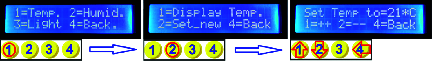
Figure 3: Setting a new desired room temperature

Figure 4: Displaying several measured or controlled parameters
The prototype was run for consecutive 24-hour periods while sensor and actuator data was recorded from the GPIO pins of the controller. During a typical 24-hour test run, a total of 23 parameters were sampled at 10 s time intervals. These parameters are used in the Results section to visually plot the system’s behavior during testing and to show how it reacts to changes in the environment.
A smart home automation system aligned with the proposed objectives was designed, and a prototype was built and evaluated. Sensor modules were placed inside and outside the house to collect and send data to a microcontroller that controls the lights, power sockets, temperature and humidity. By automatically controlling the above and by learning the user’s work schedule, the comfort level inside the house can be increased while the overall energy consumption can be reduced. The following plots were created using the data collected during the prototype’s evaluation, as detailed above.
This SHAS is designed to automatically switch the lights on/off in three areas of the house where motion sensors are installed. An ambient light sensor is also integrated into this SHAS design. When movement is detected (Fig. 5, Set 4), the controller compares the ambient light intensity provided by the sensor (Fig. 5, Set 1) with the set-point (Fig. 5, Set 2). If the ambient light intensity is higher than the set-point, there is no need to turn on the lights. If the value is lower, the lights are automatically turned on (Fig. 5, Set 3). If more than 5 min pass without movement detected, the lights are automatically switched off. This timer is adjustable to any value between 1 and 255 (the limit is set by the byte variable used to store this value). When controlled by the SHAS, the lights will never stay on while not in use. This way, it is possible to reduce the electricity consumed due to human negligence.
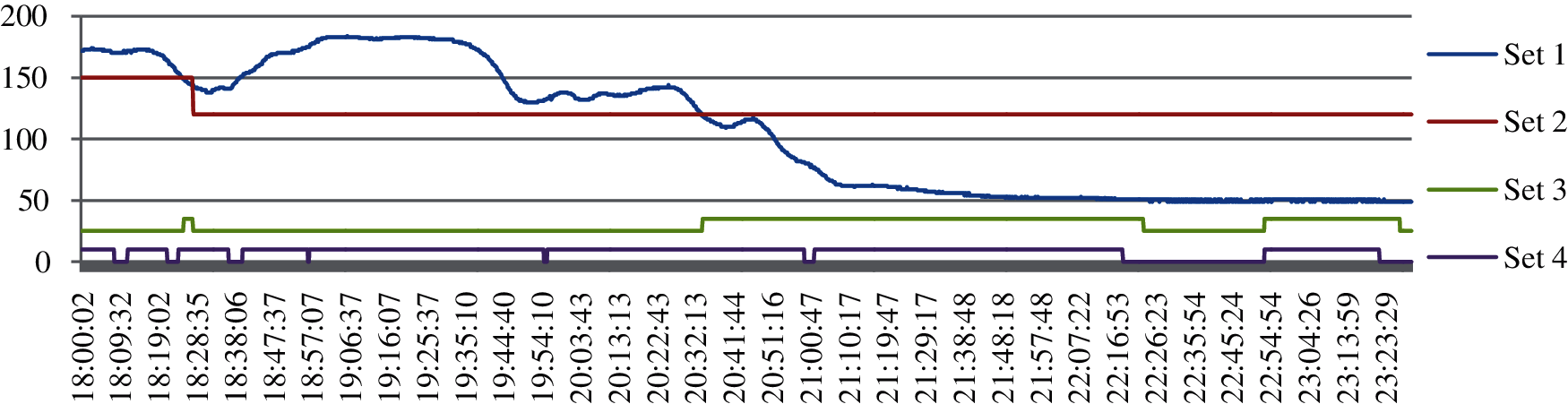
Figure 5: The lights control signals and associated system parameters *Set 1 = Ambient light intensity; Set 2 = Set point for lights control; Set 3 = Lights ON/OFF; Set 4 = Movement detected
Some home appliances consume energy even when they are not in active use (a microwave oven or multimedia system left in standby mode). Even if the energy consumed by one device in standby is small, for lengthy periods and for multiple devices, the total standby energy consumption adds up to a significant value as detailed by References [15,16]. This proposed SHAS controls the power sockets connected to it and deactivates them in certain conditions. During tests, a 10 min timer was set between the moment of the last movement detected in a room (Fig. 6, Set 2) and the moment the power sockets were disconnected (Fig. 6, Set 1). The timer is adjustable between 1 and 255 min.
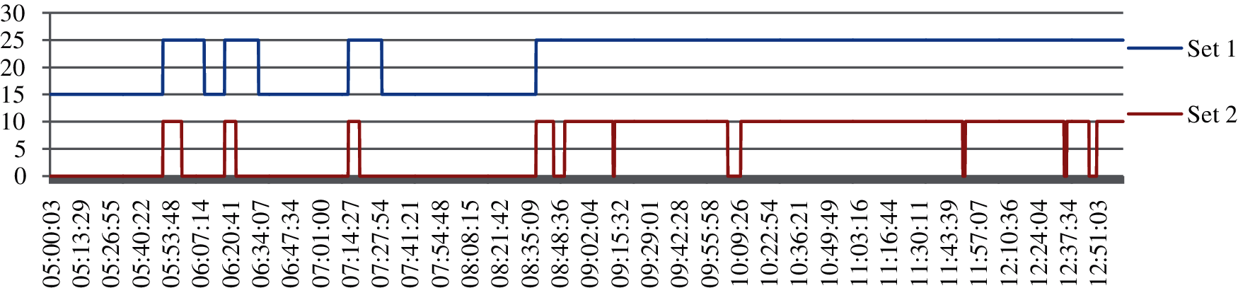
Figure 6: The control signals for the power sockets and the motion detected by sensors *Set 1 = Power sockets ON/OFF command; Set 2 = Motion sensor output (High = detected, Low = not detected)
Fig. 7 shows the power sockets and lights control for a 24 h period. The ambient light intensity and the set-point for lights control are also included.
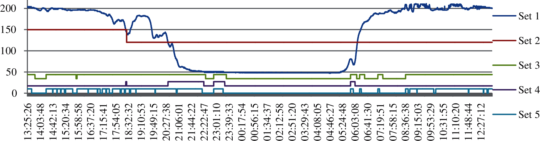
Figure 7: The ambient light intensity and the lights and power sockets control for a 24 h period *Set 1 = Ambient light libtensity; Set 2 = Setpoint for light intensity; Set 3 = Power sockets control; Set 4 = Lights ON/OFF control; Set 5 = Motion detector output
The room temperature is maintained around the set-point by controlling the room heater only when the house is occupied. To reduce consumption, the heater is not activated when the user is about to leave or when he is not at home. Fig. 8 shows the heater control signals (Set 3) in response to the ambient and set-point temperatures. When it is possible to warm up or to cool down the room without actively using energy (using the outside air), energy-saving tips are displayed to the user. Such instances are identified by comparing the indoor, outdoor and set-point temperatures, and while the opportunity exists, these notifications are displayed on the LCD every 5 min. Fig. 9 shows the system’s command (Set 4) to display an “Open windows to cool the house” notification, and it can be seen how the room temperature is lowered (Set 2). Fig. 10 illustrates several displayable notifications.
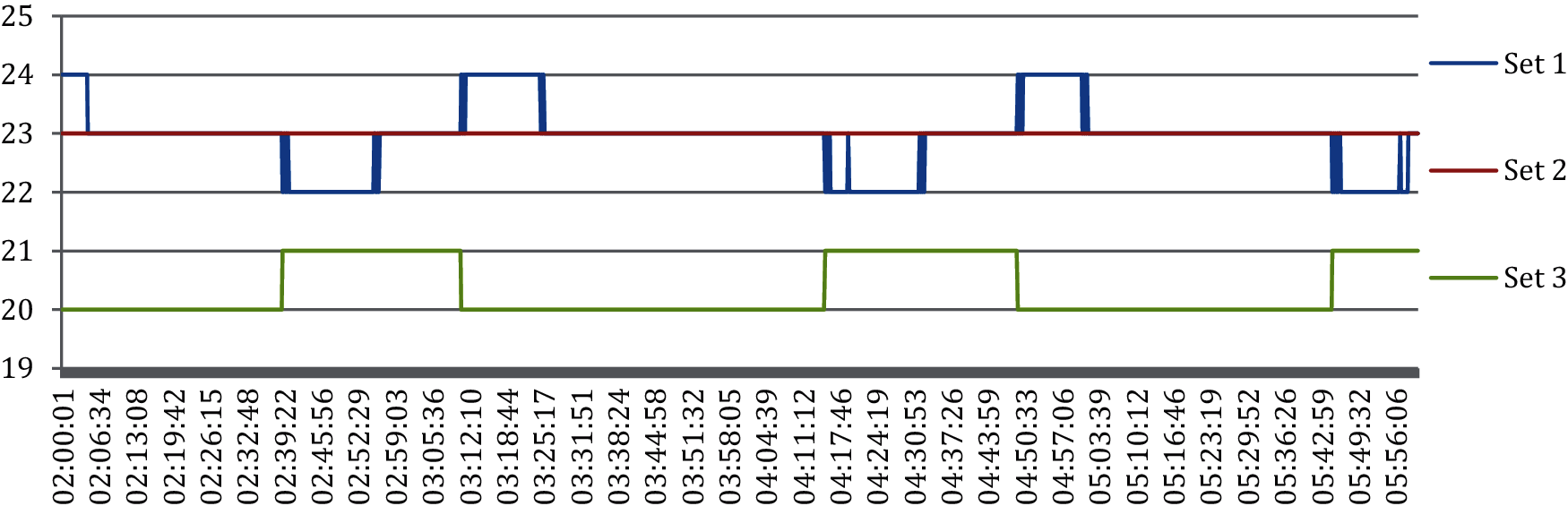
Figure 8: The heater control signals and the set point and room temperatures *Set 1 = Room temperature; Set 2 = Temperature set point; Set 3 = Heater control on/off
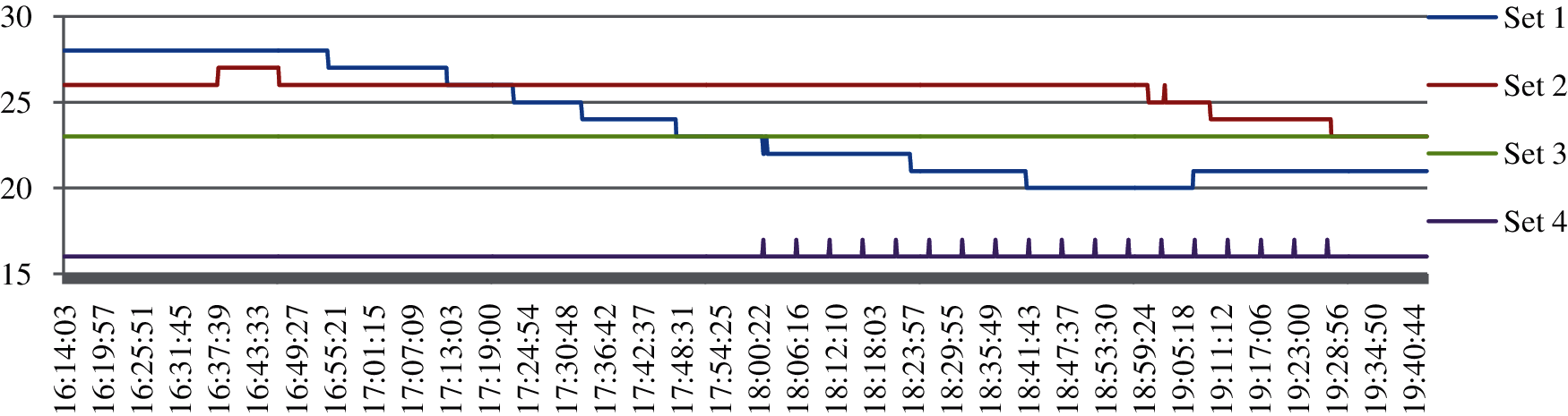
Figure 9: The system's command to display a notification, triggered by a low, outside temperature Set 1 = Outside temperature; Set 2 = Room temperature; Set 3 = Set point Temperature; Set 4 = Notification issued
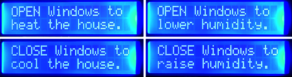
Figure 10: Examples of power-saving tips displayed by the system
Humidity control inside the house is important, as too much or too little air humidity can lead to health problems. During testing, a dehumidifier was switched on when the interior air’s humidity level surpassed the set-point (Fig. 11, Set 4). The inside and outside air humidity levels were both monitored and the SHAS notified the user when it was possible to bring the air’s humidity level closer to the set-point with no energy consumption, simply by opening a window. (some notifications shown in Fig. 10).
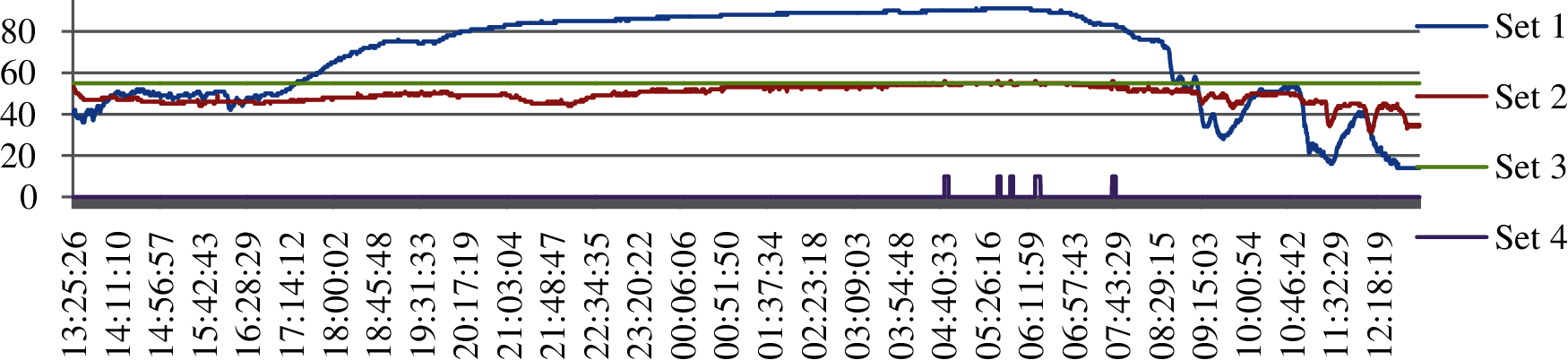
Figure 11: The dehumidifier control signals and the associated system parameters Set 1 = Outside humidity; Set 2 = Room humidity; Set 3 = Humidity Set point; Set 4 = Dehumidifier command
This safety feature of the SHAS was tested (in a controlled environment) by exposing the MQ-2 gas sensor to a small quantity of methane gas. During this time, the sensor measured a gas level higher than the safety limit (set at 30 units for testing), and two times an alert was triggered. Fig. 12 shows the methane gas level as measured by the sensor and the alert command triggered when the measured value rises above the set-point. If a gas leak is detected while the house is occupied, an aural alert is generated and associated with a notification displayed on the blinking LCD to alert the user immediately (seen in Fig. 13). If the house is unoccupied, a text message is sent to the user’s mobile phone (seen in Fig. 14).
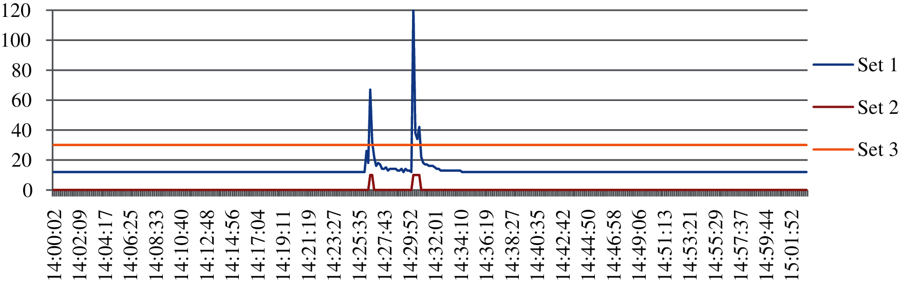
Figure 12: Gas level measurements and alert signal commands *Set 1 = Gas sensor measurements; Set 2 = Command to execute the alert routine; Set 3 = Set-point
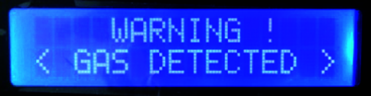
Figure 13: The system's LCD notification for gas leak detections
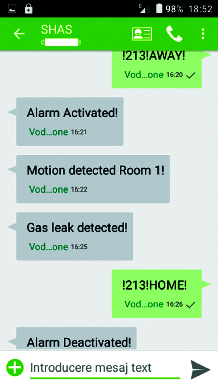
Figure 14: Text messages sent between the user and the SHAS
5.6 The Safety and Security Functions Plus the GSM Communication
When the user leaves the house, he can activate the system’s security functions by sending the following text message command “!213!AWAY!”. This command instructs the SHAS to monitor the house and to take energy-saving actions without delay. In response, the user receives a text message informing him that the alarm function is now active. This safety function activates automatically when no movement is detected by any sensor for more than 24 h. While the resident is away, he will receive text notifications on his mobile phone each time abnormal events (motion or gas leaks) are detected at home (Fig. 14). When returning home, the user can notify the system by sending a text command (“!213!HOME!”) or by entering a PIN code (Fig. 15) using the numeric keypad included in the system’s architecture. This command instructs the SHAS to deactivate the alarm function and to resume normal home control operations. The GSM communication can be protected against unauthorized interference either by accepting commands only from certain telephone numbers or by including a PIN code (e.g., 213) in every text message, as tested. The same PIN code used to locally deactivate the system’s alarm function using the numeric keypad must be included in the text command.
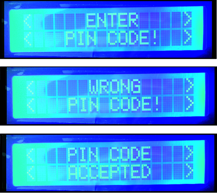
Figure 15: Possible notifications displayed by the SHAS when entering a PIN code using the keypad
5.7 Cost Analysis of the System’s Components
Tab. 1 contains a list of all SHAS components and their purchase price expressed in Euros. These prices were recorded in August 2020, without including the shipment and labor costs. The proposed SHAS design is affordable as it contains only low-cost modules. The total price of all components is 58.81 Euros, an easy buy in most European Union countries.
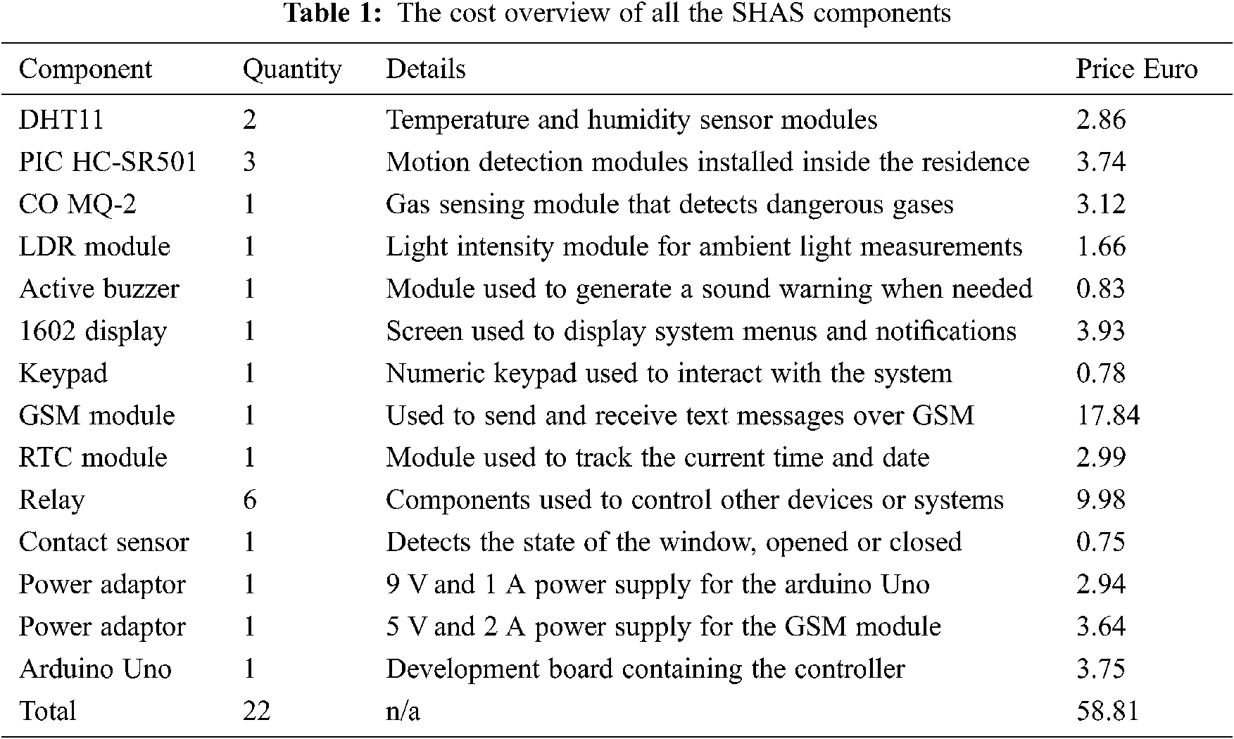
Cost-related, the system is within the desired specifications and well below the average price of similar systems available in the market. In the United States of America, the price of such a SHAS ranges between USD 275 and 1573, with the average at USD 924. Considering the exchange rates in August 2020, the proposed SHAS (components only) would cost USD 63.30, making it extremely attractive in the United States of America markets as well.
This paper presents the design and prototype evaluation of a low-cost learning and advising smart home automation system. The main feature of this SHAS is its ability to learn the user’s daily work schedule and to autonomously adapt to random changes when detected, a complex feature expected in high-end systems, not in low-cost ones. In addition to improving the user’s comfort, the proposed SHAS assists in reducing the home’s energy consumption by identifying energy-saving opportunities and notifying the user accordingly, hopefully raising the user’s environmental awareness in the process. In contrast to the “all-wireless” current trend seen in home automation systems and devices, we proposed a wired, serial inter-module communication method combined with a GSM long-distance one. Compared to the all-wireless architectures that are visible online and dependent on the network environment for normal operations, the serial communication method used by the proposed SHAS is less prone to signal interference and using the GSM technology, the system is invisible online and less vulnerable to cyber-attacks. A system prototype was built, and it behaved as expected, responding to changes in the environment as desired.
Using the Arduino Uno development board and compatible sensor and actuator modules, a scalable design was achieved that is inexpensive and easy to replicate. All the SHAS components cost approximately 58 euros (in August 2020). Upgrading the system’s control software is achievable without professional assistance as the popular C/C++ programming language used is familiar to most scholars.
The system’s wide array of sensors, multiple complex features and low-cost architecture should make this design attractive to many potential users. The system’s limitations, such as the small LCD, basic GUI and labor-intensive installation process, might discourage others.
There is no perfect home automation system, and now that our prototype proved this concept to be viable, this design too can further be improved before being installed into more houses. A first example could be the development of a dedicated complex mobile app to act as a GUI for system configuration purposes instead of the locally implemented solution. A second example could be the replacement of the Arduino Uno development board with the Arduino Mega. This change would allow for more modules to be integrated and extend the system’s architecture but would also increase its overall cost. Finally, the Arduino Nano development board could be used instead of the Arduino Uno. The Nano has similar performance to the Uno, but it is smaller and has lower energy consumption, making for a more energy-efficient device. Implementing these changes and analyzing cost/benefit results would be interesting as a further study.
Acknowledgement: PhD. Prof. Chioran Viorica is acknowledged for her administrative support and Eng. Chioran Ioan for his technical support.
Funding Statement: The authors received no specific funding for this study.
Conflicts of Interest: The authors declare that they have no conflicts of interest to report regarding the present study.
1. Statista statistics portal, SHAS in USA. [Online]. Available: https://www.statista.com/outlook/279/109/smart-home/united-states#market-users. (Accessed on: 02 June, 2020). [Google Scholar]
2. Research and Markets, Global Smart Homes & Home Automation Ecosystem 2019–2023. Available online at: https://www.globenewswire.com/news-release/2019/11/06/1942452/0/en/Global-Smart-Homes-Home-Automation-Ecosystem-2019-2023-Revenues-from-Shipments-of-Home-Automation-Systems-in-Europe-NorthAmerica-Will-Grow-at-a-CAGR-of-19-8.html. (Accessed on: 02 June, 2020). [Google Scholar]
3. United States Energy Information Administration. Available online at: https://www.eia.gov/energyexplained/index.php?page=electricity_in_the_united_states. (Accessed on: 02 June, 2020). [Google Scholar]
4. Eurostat online statistics. Available online at: https://ec.europa.eu/eurostat/statisticsexplained/index.php/Energy_consumption_in_households#Energy_consumption_in_households_by_type_of_end-use. (Accessed on: 02 June, 2020). [Google Scholar]
5. P. V. Gaikwad and Y. R. Kalshetty, “Bluetooth based smart automation system using android,” International Journal of New Innovations in Engineering and Technology, vol. 7, no. 3, pp. 24–29, 2017. [Google Scholar]
6. T. W. Lai, Z. L. Oo and M. M. Than, “Bluetooth based home automation system using android and arduino,” in Proc. of the 2nd Conf. on Computer Application and Research (CCAR 2018Taunggyi, Mayanmar, pp. 123–130, 2018. [Google Scholar]
7. N. V. Santhoshsivan, S. Senthilkumar, K. Arunkumar, S. Umasankar and M. Jagadeeshraja, “Home automation using smartplug,” International Research Journal of Engineering and Technology (IRJET), vol. 6, no. 3, pp. 8173–8177, 2019. [Google Scholar]
8. M. Naing and N. S. Hlaing, “Arduino based smart home automation system,” International Journal of Trend in Scientific Research and Development (IJTSRD), vol. 3, no. 4, pp. 276–280, 2019. [Google Scholar]
9. J. S. Peter, S. Selvakumar, H. Pandit and P. Aggarwal, “Home automation and home security using arduino and ESP8266(IOT),” International Journal of Innovative Technology and Exploring Engineering (IJITEE), vol. 8, no. 7S, pp. 39–42, 2019. [Google Scholar]
10. X. Song, “Design of smart home system based on power line communication technology and wireless sensor networks,” Chemical Engineering Transactions Journal, vol. 51, pp. 757–762, 2016. [Google Scholar]
11. Y. L. Hsu, I. P. H. Chou, H. C. Chang, S. L. Lin, S. C. Yang et al., “Design and implementation of a smart home system using multisensor data fusion technology,” Sensors Journal, vol. 7, pp. 1631, 2017. [Google Scholar]
12. M. Collotta and G. Pau, “A solution based on bluetooth low energy for smart home energy management,” Energies Journal, vol. 8, pp. 11916–11938, 2015. [Google Scholar]
13. Q. Hu and F. Li, “Hardware design of smart home energy management system with dynamic price response,” IEEE Transactions on Smart Grid, vol. 4, no. 4, pp. 1878–1887, 2013. [Google Scholar]
14. V. L. K. B. Manda, N. Ramasubramanian and V. Kushal, “An elegant home automation system using GSM and ARM-based architecture,” IEEE Potentials, vol. 37, no. 5, pp. 43–48, 2018. [Google Scholar]
15. P. Delforg, L. Schmidt, S. Schmidt, P. Remick, P. Delforge et al., (The Natural Resources Defense Council, San Francisco, California, USALisa and S. Schmidt (Home Energy Analytics, Los Altos, California, USA“Home idle load: Devices wasting huge amounts of electricity when not in active use,” A Report by the Natural Resources Defense Council, pp. 1–36, 2015. [Google Scholar]
16. Consumer guide on standby losses of appliances, Selina Project. [Online]. Available: https://ec.europa.eu/energy/intelligent/projects/sites/iee-projects/files/projects/documents/selina_consumer_guide_en.pdf. (Accessed on: 02 June, 2020). [Google Scholar]
 | This work is licensed under a Creative Commons Attribution 4.0 International License, which permits unrestricted use, distribution, and reproduction in any medium, provided the original work is properly cited. |