DOI:10.32604/iasc.2022.016116
| Intelligent Automation & Soft Computing DOI:10.32604/iasc.2022.016116 | |
| Article |
Requirement Design for Software Configuration and System Modeling
1Department of IT and Computer Science, PAF-lnstitute of Applied Sciences and Technology, Haripur, Pakistan
2Department of Computer Science, COMSATS University Islamabad, Wah Campus, Pakistan
3Department of Computer Science & IT, The Islamia University of Bahawalpur, Bahawalpur, Pakistan
4Industrial Engineering Department, College of Engineering, King Saud University, P.O. Box 800, Riyadh 11421, Saudi Arabia
5Department of Information and Communication Engineering, Yeungnam University, Gyeongsan, 38541, Korea
*Correspondence: Muhammad Shafiq. Email: shafiq@ynu.ac.kr
Received: 23 December 2020; Accepted: 09 April 2021
Abstract: Software Configuration Management (SCM) aims to control the development of complex software systems. Traditional SCM systems treat text files as central artifacts, so they are mainly developed for source code. Such a system is not suitable for model-based software development with model-centric artifacts. When applying traditional systems to model-based software development, new challenges such as model mapping, differentiation, and merging arise. Many existing methods mainly use UML or domain-specific languages to determine model differences. However, as far as we know, there is no such technology for System Modeling Language (SysML) models. SysML covers the entire development life cycle of various complex systems, covering information, processes, hardware and software. SysML contains nine types of diagrams for system modeling. One of them is the SysML requirement diagram, which is used to capture the functional requirements of the system. We propose a differentiation method for the SysML demand model. We recommend to create a SysML requirement model in the CASE tool first, and then export the SysML model in the form of XMI. Then, we parse the XMI representation through difference calculations. Finally, we summarize the results in annotated form. We implemented our method in a satellite system case study and demonstrated the experimental use of the method.
Keywords: Software configuration management; model-driven engineering; systems modeling language; model differencing; requirement diagram
The development of complex software system development requires coordination between different team members working in actual projects [1]. Among them, configuration management is accomplished by identifying, organizing, and controlling the modification of the software being built by the programming team [2]. In a complex and extended system, maintaining discipline is the main goal of configuration management [2–5]. Xu Gang et al. [1] clearly pointed out that the Capability Maturity Model Integration (CMMI) only provides software setup guidelines, so the lack of a clear workflow model leads to increased budgets. In this regard, software configuration management (SCM) is the specialization of computer programs and related documents. Among them, many tasks need to be performed, such as difference detection between software artifacts, version management, conflict detection, etc. [6]. Such a model is the only source of information in our software engineering. However, the lack of a controllable mechanism will lead to high costs, project delays and quality problems [7].
Many existing methods mainly use Unified Modeling Language (UML) or domain-specific languages (UML) to determine model differences [8–10]. In this regard, Model Driven Engineering (MDE) aims to reduce the complexity of software development by treating models as central artifacts [11–13]. This type of model must be designed, analyzed, and maintained according to the version control mechanism, and the quality of the model must be ensured. However, while treating models as core artifacts, traditional SCM systems also present new challenges. For many reasons, traditional version control systems (VCS) (such as Subversion) and concurrent version control systems (CVS) are not suitable for performing configuration management tasks on models. For example, in MDE software, documents are both text files and models, just like different types of diagrams in UML. These diagrams are usually stored in XML Metadata Interchange (XMI) format to facilitate interpretation and manipulation of system models. The order of these parts of the text has nothing to do with the file. Therefore, the CASE tool can store parts representing classes or other chart elements in any order. The order of the text lines and their layout information is not important for model distinction and model merging operations. To this end, System Modeling Language (SysML) may be helpful because it spans the entire development life cycle of various complex systems, covering information, processes, hardware, and software. For system modeling, SysML consists of nine types of diagrams. One of these diagrams is a SysML requirement diagram, which is used to capture the functional requirements of the system. However, as far as the author knows, there is no method that covers the model differences and version control methods of SysML models.
In this article, we propose the SysML demand model difference method. The method we propose includes creating a SysML requirement model in the CASE tool, exporting the SysML model in XMI representation, parsing the XMI representation, performing difference calculations and finally displaying the difference results in the form of annotations. We implemented the proposed method in a case study of satellite systems and showed its usefulness.
The rest of this article is arranged as follows. Section 2 introduces related work. Section 3 articulates the demand design of the satellite system in the form of case study. Section 4 focuses on the solution to the demand difference proposed for the SysML model. Section 5 presents the results of our experiment. Section 6 draws conclusions and makes recommendations for future work.
There are several model-based SCM solutions in the literature. In the following, we will focus on research work related to MDE, model version control and SysML.
The model is stored in a centralized location in the MDE environment. The evolution of MDE is a new standard that can control the extensive use of models in the entire software development process [14]. It improves the level of design abstraction level to provide model portability, interoperability, maintainability and reusability [15]. From the developer’s point of view, an important problem is the lack of good tool support for creating software programs in a simple and effective way [16]. This shift has brought some new research challenges. In order to achieve team-based model development, model version control is one of the challenges [17]. The rise of new challenges has caused active research areas ranging from model differentiation to model merging. Therefore, efforts are being made to contribute to this new stimulating research field [17]. A centralized software engineering version control system is needed, which should allow a team of developers to operate on the specified model at the same time, and is sufficient to integrate model operations to obtain a merged version of the new model [18,19]. In Koegel et al. [20], an extensive summary of the VCS Alliance functions for software artifacts discusses advanced systems for model artifacts and provides an important competition for considering future model version control systems [20]. A comparison of state-based and operation-based methods is discussed in Wang et al. [21], which is used to check and understand model changes. The new era of SysML modeling language has been jointly developed and standardized by the Object Management Group (OMG) and the International Council of Systems Engineering (INCOSE) [22–24].
The use of SysML has brought many benefits and potentials in several complex applications such as avionics [25–27]. In order to design complex systems, SysML provides simple graphics. It covers not only the software aspects of complex systems, but also the hardware aspects. Among them, it simplifies the system description in the early design stage with graphical symbols and easy-to-understand methods [28]. The expression control and simulation functions of SysML contribute to the early prototype design, verification and validation of the system [29]. An outstanding work of CubeSat with the help of SysML is discussed in Bahcivan et al. [30]. We can find the model-based SysML for CubeSat framework and its application in the Radio Aurora Explorer task in Sayanjali et al. [31]. Another method using SysML is applied to remote sensing satellite systems to use infrared technology to capture images [32]. Among them, the use case extractor evaluates the automatic evaluation of the use case model. In Muetzelfeldt et al. [33], the diagram was designed in Star UML and exported to a UML file, which was stored and retrieved in the database for automatic evaluation. Another study studied the difference and combination of models in the version control system [34]. In the version control system, the distinction, merging and union of the two models used to detect conflicts and their solutions have been completed. One of the main examples of using meta-identifiers to exchange meta-models with Object Management Group (OMG) standards is discussed in García-Holgado et al. [35]. The research in Maoz et al. [36] focused on the management of model changes developed over time. In Lanceloti et al. [37], the author proposed a UML model parser in XMI format to facilitate data processing. The main purpose of creating XMI is to obtain a standard method of exchange in UML models. In Deeptimahanti et al. [38], the author uses the domain-independent tool UMGAR to describe the UML model generator from natural language. The tool also provides visualization of UML-generated models that provide a general XMI parser and supporting models (including relationships). This function is of great significance to UML modeling using tools in the future.
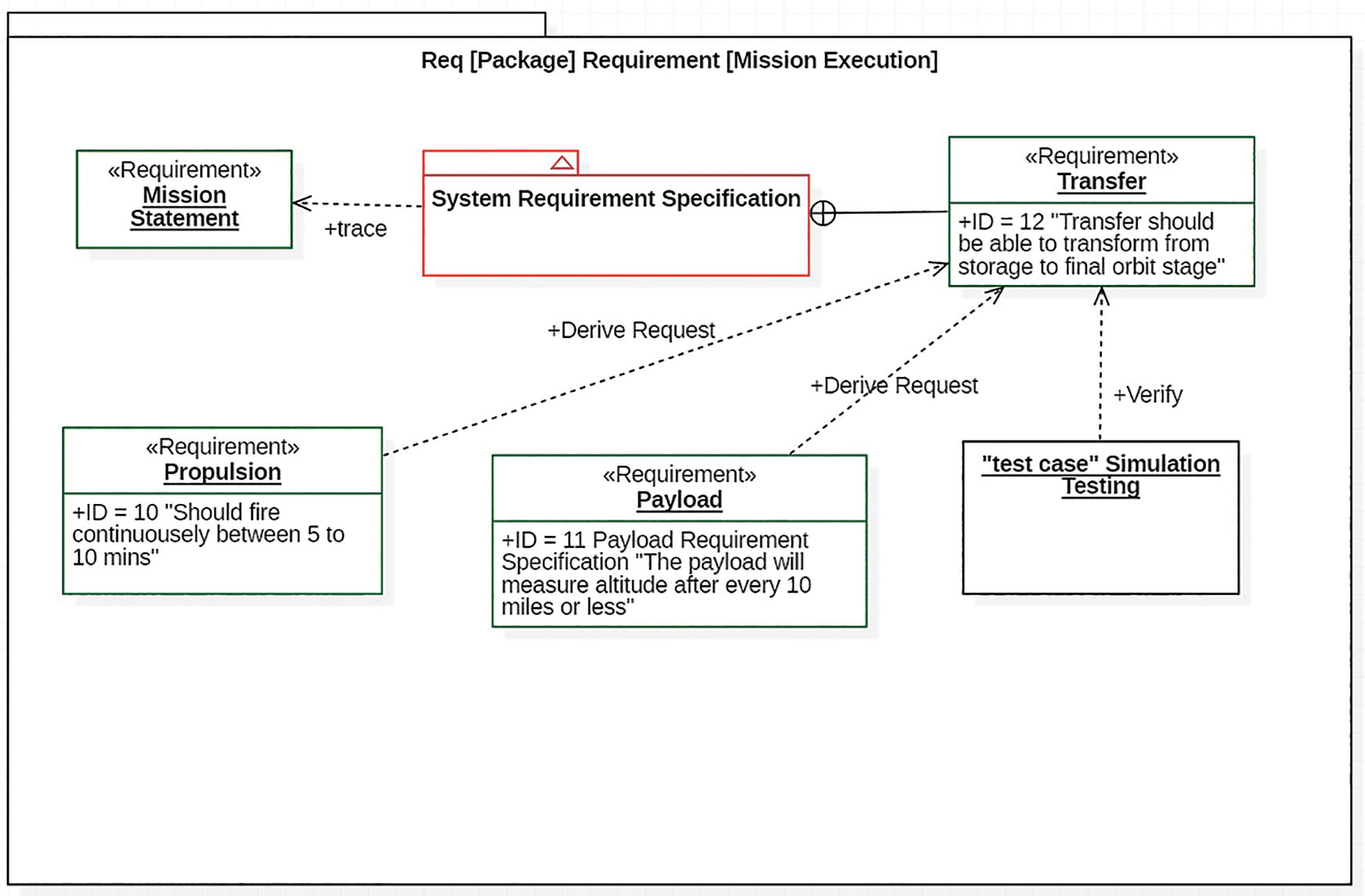
Figure 1: Requirement diagram version 1 (Satellite)
The SysML requirement diagram is used to express the traceability between requirements. Typically, text-based requirements will be generated to show the requirements and their relationships, including their IDs and specifications. The abbreviation of the demand graph is Req, including the namespace. In our example, the Req graph namespace is a task statement. The framework can be expressed in any form of the following model elements, including packaging, models, model libraries, and views. The requirements presented in the system have the prototype <<Requirement>> and its ID and text-based description. In our case, four requirements were created for the satellite conceptual requirements map, as shown in Fig. 2. These requirements are mission description, transfer, ID = 12, advancement, ID = 10, payload, ID = 11. The relationship numbers used in the demand diagram are tracking, derivation of requests, and verification. The trace relationship describes the type of dependency relationship. In our case, the tracking relationship means that system requirements will be tracked to task requirements. Since derivation, request to display the child elements of the parent element. Therefore, both the propulsion force and the payload come from the transmission requirements. Verify another relationship used in the model, which is a behavior created in the system to show the function of a specific structure. It can be defined anywhere in the system model. In our case study, simulation tests can verify actual transmission requirements. Test cases are used to verify all system requirements.
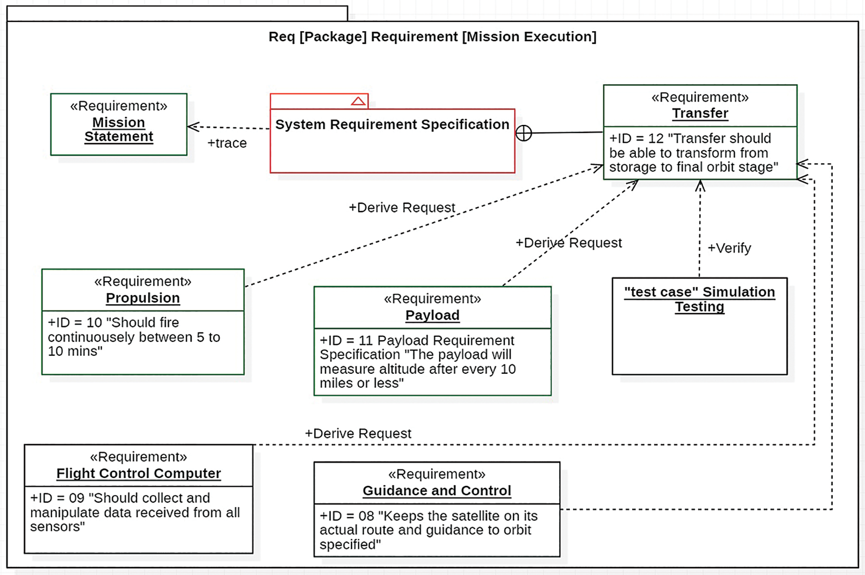
Figure 2: Requirement diagram version 2 (Satellite)
For the application of model version control and differentiation technology, the two versions of the demand diagram are designed as shown in Figs. 1 and 2. In accordance with the changes in requirements, two system requirements have been added in the next version 2, namely “flight control computer” and “guidance and control” which depend on the transfer requirements. These system requirements are marked with IDs 09 and 08, respectively. The relationship between transmission requirements and system requirements specifications is represented by a solid line with a circled plus sign. Contains the transfer of the namespace represents the elements of the package system requirements specification.
We show the integrated diagram of the proposed demand differentiation method in Fig. 3. The main four steps include different sub-methods and functions of our method. The component “model generation” means a model created in the CASE environment. Component XMI generation automatically generates files for parsing through StarUML. The parsing model component is used to parse the exported model using code generation in the Java language. The version control component is used to compare between version 1 and version 2 of the XMI requirement map stored in the repository. The result shows the required mapping, model nodes added and deleted.
To perform our work, we used two softwares, namely StarUML for the development of SysML models, and JavaNetBeens/MySQL for parsing and distinguishing methods. The open source free modeling software StarUML is used to develop fast and extensible system models. The software has true model-driven architecture (MDA) support, and also provides an XMI export function, which is necessary for the method to calculate the model version by automatically generating code from the UML generated diagram to realize the difference algorithm. NetBeans IDE is a full-featured platform for developing various JAVA applications. It is open source and provides extensive support for MySQL database for repository generation and user access control. It contains an easy-to-use interface with high productivity and speed.
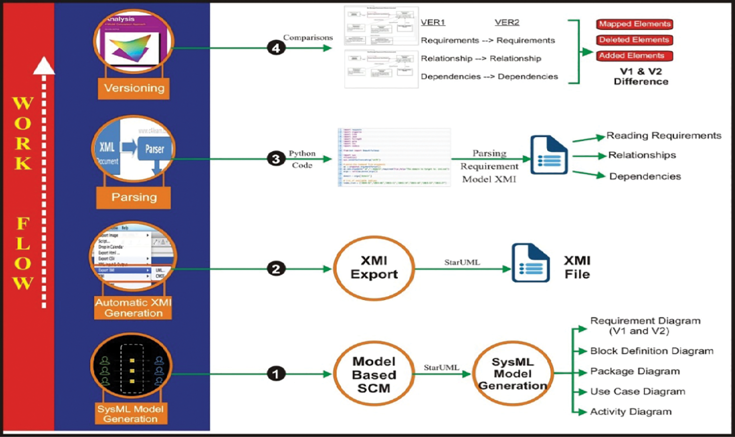
Figure 3: Integrated diagram of approach (Work Flow)
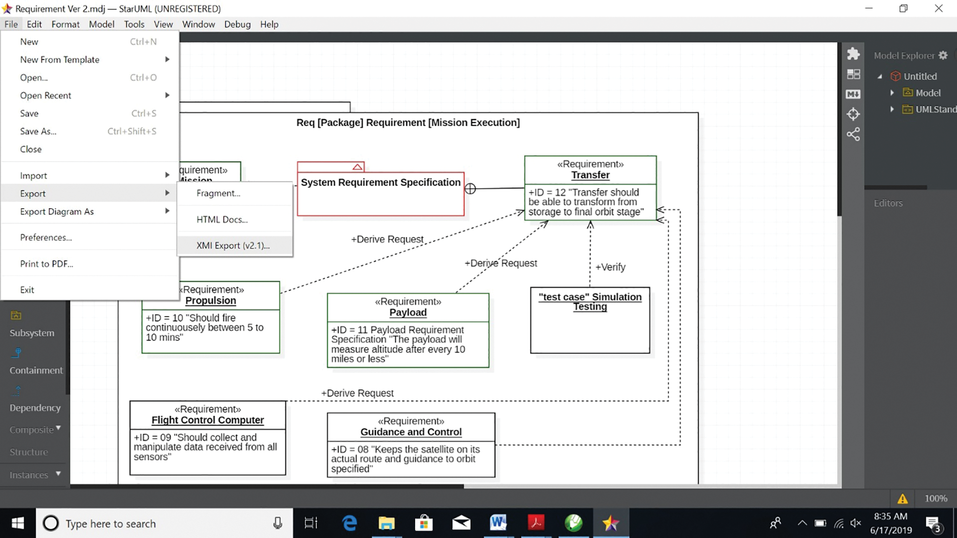
Figure 4: XMI export using StarUML
All system models are produced in StarUML, which is a free design tool and has the function of automatic XMI export. XMI provides a standard method for exchanging information between stakeholders. The special purpose of XMI is to transfer system models generated in different tools to each other. XMI follows the standards of W3C, UML (OMG) and Meta Object Function (MOF). Fig. 4 shows the process of XMI export. The generated XMI is stored in a central repository for version control and controlled access to perform model differentiation methods.
Parsing (or syntax analysis) is the process of analysing XMI content. Operate on such contents of XMI to extract requirements and their relationships. The exported XMI of version 1 and version 2 of the demand map stored in the resource library is parsed by the JAVA parser. The code used to parse the XMI file is shown in Fig. 5.
We define “Model Diff” as a measure of similarity and difference between different model versions. Most of the previously completed research was motivated by UML-generated models. The amount of research focused on the model differences of use cases and UML class diagrams. The purpose of this research is to develop model-based software solutions for the unrealized SysML demand model. The calculation process of the model difference between the two demand diagrams of SysML is explored as follows:
• Delta Δ Calculation Delta is calculated as difference of models.
• Selection of Case Study SysML Requirement Diagram Versions.
• Algorithm Design Difference Calculation.
The difference between the two versions of the model is called Delta Δ. We will compare storage version 1 and version 2 and increments. Two versions of the demand graph are mapped to calculate Delta Δ:
• Requirements version 1 Requirements version 2 (Added)
• Requirements version 1 Requirements version 2 (Removed)
• Dependent Elements of Ver 1 Dependent Element of version 2 (Added/Removed)
• Dependencies version 1 Dependencies of version 2 (Added/Removed)
• Relationships version 1 Relationships version 2 (Added/Removed)
Delta of models can be computed as: ReqModel2 – ReqModel1 = Delta Δ.
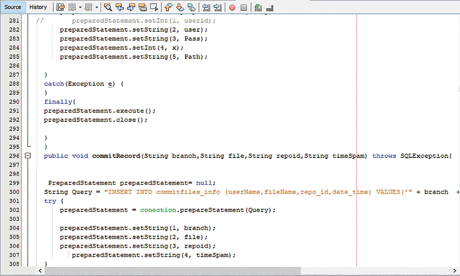
Figure 5: Java code for XMI parsing
4.3.2 Model Comparison Criteria
Only in identifiable situations can two different versions of the model be compared. The object can be identified only if it has a unique identifier with a certain structure inside the model. Otherwise, it will not be recognized as a model object.
The basic structure of the model should remain unchanged, while the track of change only belongs to the same project. The information that needs to be considered needs to be defined for each model and its new instance (or version). Multiple models need to define different comparison standards. Methods can be classified based on the following criteria:
• Standards based on unique identifiers: Each item has a unique identifier.
• Criteria based on similarity: Syntactic information based on comparison items.
• Language-specific standards: Only apply to specific languages.
The two different versions of the requirements model are stored in the following pattern:
• Mapped Requirements MR [ ] (for model requirements that are similar in both versions)
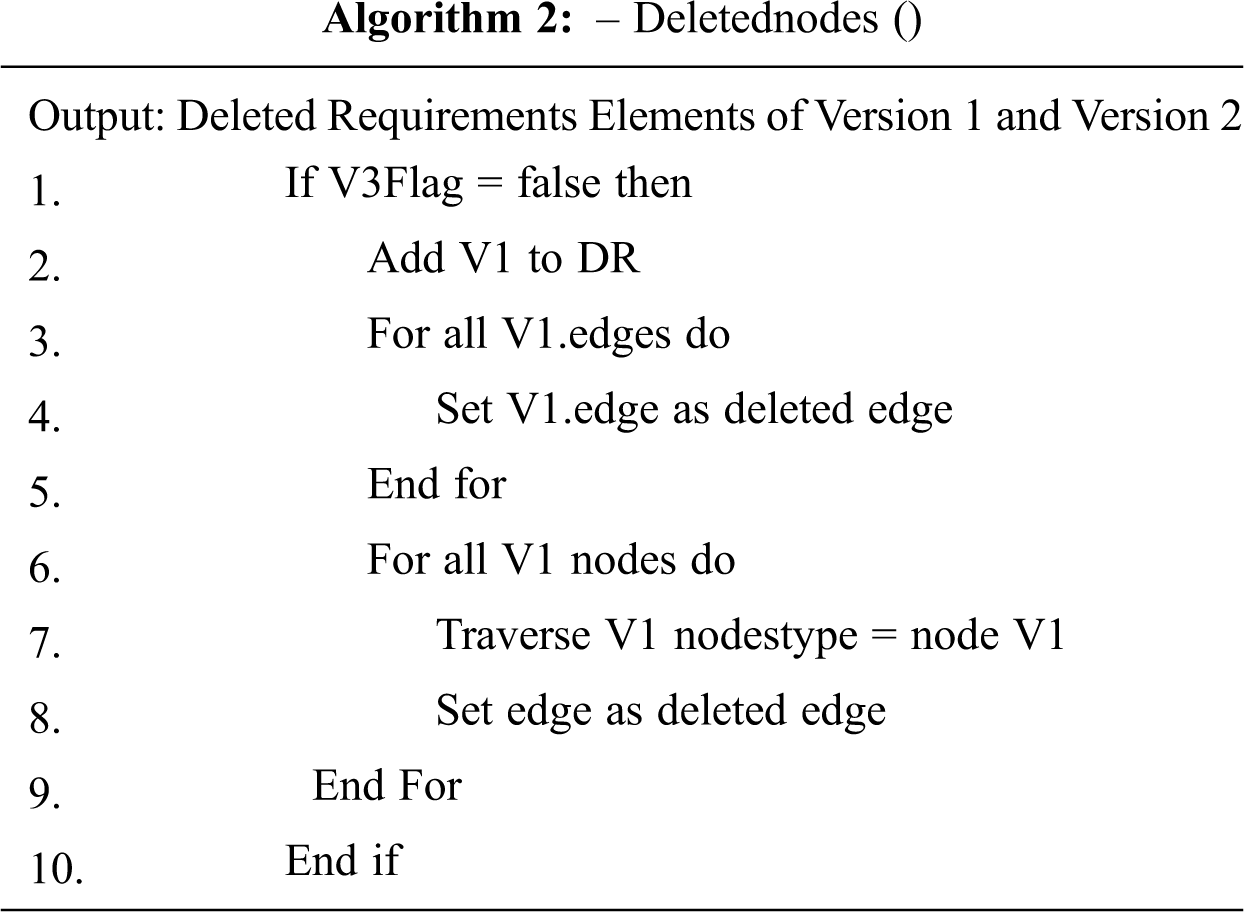
• Deleted Requirements DR [ ] (for model requirements present in version1 and are deleted in version 2)
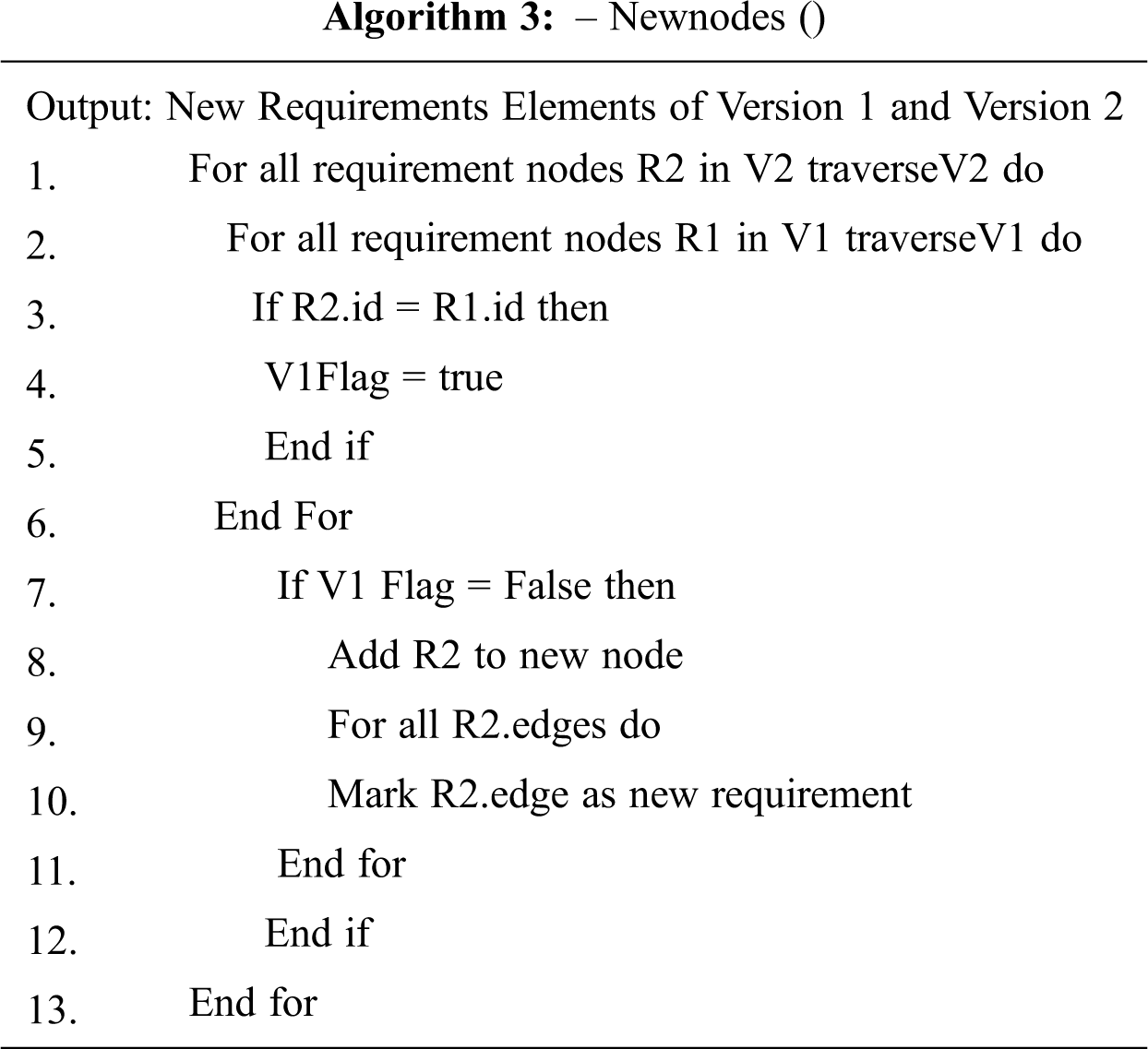
• New Requirements NR [ ] (for model requirements that are newly added)
CheckMR [], CheckDR [], CheckNR [] process two different versions of the demand model as input and generate two sets of outputs. a) MRSet [] and b) ChangeSet []. MRSet[] contains similar model elements in the two versions, and Changeset[] contains specific model elements that have changed compared to version 2.
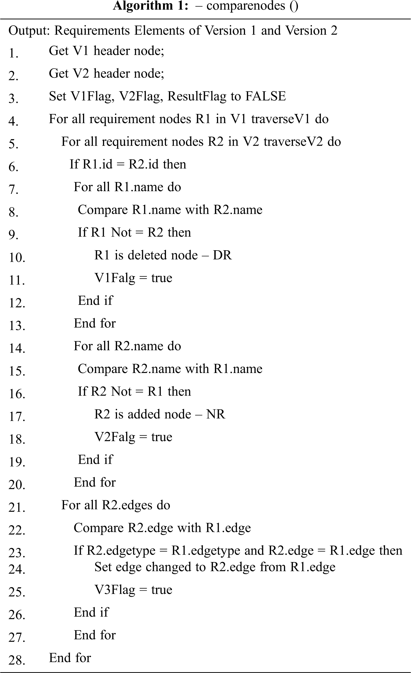
Consider comparing the structural and syntactic properties of two model elements. Structured attributes store the relationship and dependency information between model elements. Instead, the syntactic information contains the demand name and text description of a specific name, including its ID number. The working principle of the difference algorithm is as follows. First, compare all requirements in version 1 of the chart with all requirements in version 2 for mapping sets, adding sets, and deleting sets. Similarly, all the dependencies and their types in version 1 are mapped with the dependencies of version 2, and the addition and deletion sets are compared.
Consider comparing the structural and syntactic properties of two model elements. Structured attributes store the relationship and dependency information between model elements. Instead, the syntactic information contains the demand name and text description of a specific name, including its ID number. The working principle of the difference algorithm is as follows. First, compare all requirements in version 1 of the chart with all requirements in version 2 for mapping sets, adding sets, and deleting sets. Similarly, all the dependencies and their types in version 1 are mapped with the dependencies of version 2, and the addition and deletion sets are compared.
Case study 1 (satellite) analyzed the information extracted from demand models 1 and 2, and its output is shown in Fig. 6. The version 1 requirements diagram outputs all the requirements mentioned in the first model. On the other hand, requirement version 2 produces the output of all requirements used in the second version of the model. The version differences are shown in the last two rows, where version 1 shows zero differences, while version 2 describes the new system requirements for guidance and control and flight control computers.
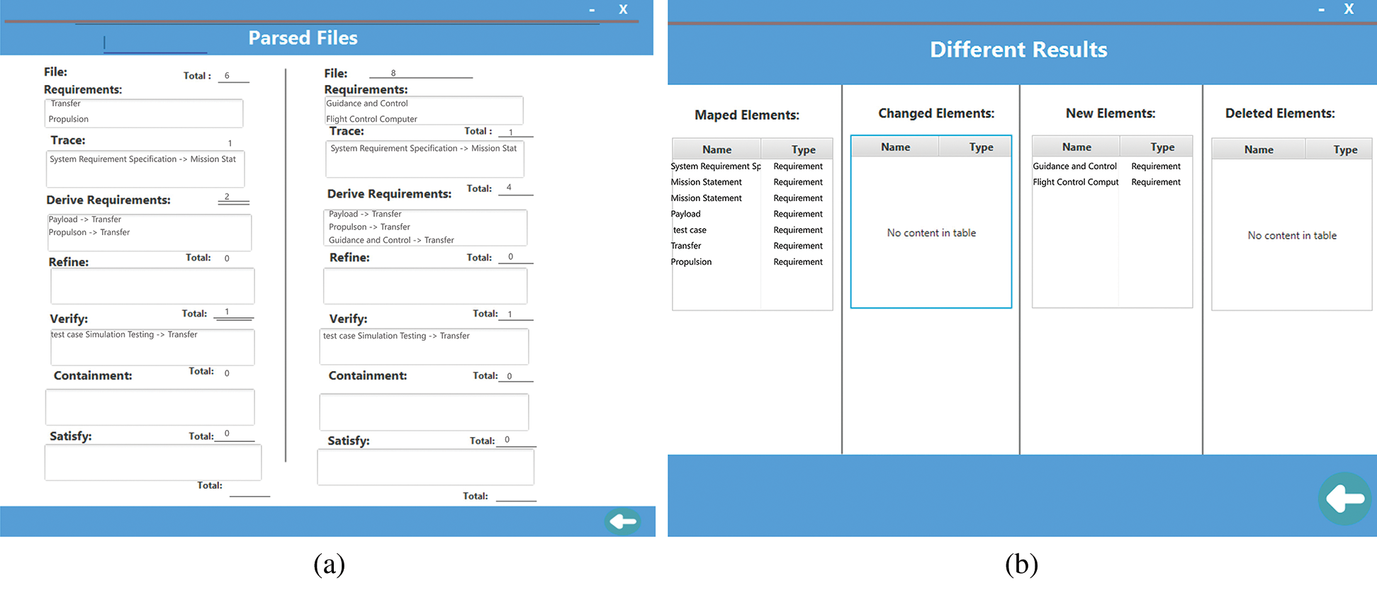
Figure 6: Parsed output of requirement diagram version 1 and version 2 with model differencing (a) Experiment result version 1 (b) Experiment result version 1
This section discusses the results of the implementation. The model differentiation result of the demand diagram is called Delta Δ label. Tab. 1 shows the total number of differences found in version 1 (V1) and version 2 (V2). In the case study, there are 6 demand in V1 and 8 demand in V2. In this case, the increment is 2. Fig. 7 shows the incremental graph between the requirements of V1 and V2.


Tab. 2 shows the detailed differences between the case studies between V1 and V2. In this case study, two requirements “guidance and control” and “flight control computer” have been added to version 2. The difference in the relationship between V1 and V2 of the two case studies is shown in the Tab. 3. There are 4 relations in V1 and 6 relations in V2. Therefore, the gain (∆) is 2. In Fig. 8, we obtain the increment between the relationships. In V1, there are 10 (06 + 04)/10 (04 + 06) requirements and the sum of their relationships. In V1, there are 14 (08 + 06)/14 (06 + 08) requirements and their relationships in V2. Tab. 4 shows the relationship and the total number of relationships. Among them, the total Delta Δ count is 4.
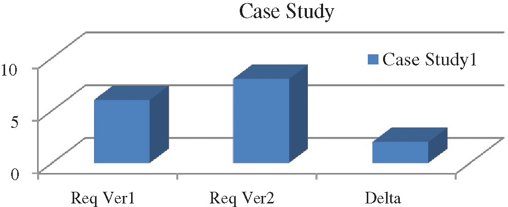
Figure 7: Delta graph of requirement diagram in version 1 and version 2

Figure 8: Graph of delta relationships case study 1
In this article, we discussed configuration management issues in model-based software configuration management. We divide the SCM system into file-based and model-based SCM systems. The traditional SCM system is a file or text-based system (for example, a source code management system). Software development is a model-centric process in which MDE applies UML models for analysis and design purposes. Since the models are conceptual diagrams, they cannot be treated as text files. For this reason, file-based SCM systems are only valid for source code files or other text software artifacts. However, they are not valid for software artifacts with graphical representations. We propose a model-based SCM solution for the SCM activity and difference detection represented by the model. We apply the method to the analysis phase of software development, where the demand diagram is used to capture the demand. Because the traditional file-based SCM system cannot handle the paradigm shift of MDE in software development. However, our approach performs SCM activities at the appropriate abstraction level of the SysML model. The proposed technology can also be used as a future extension for verification and validation of the design system. Models developed in SysML can be simulated. This can be achieved by using some simulation tools (e.g. Modilica). Before actual development and implementation, the designed system can be fully tested, which will save costs and reduce errors. Version control tools can also be applied to new models to track changes and manage version control.
Acknowledgement: The authors extend their appreciation to King Saud University for funding this work by Researchers supporting project number (RSP-2020/133), King Saud University, Riyadh, Saudi Arabia.
Funding Statement: The research work was supported by Researchers supporting project (RSP-2020/133) of King Saud University, Riyadh, Saudi Arabia.
Conflicts of Interest: The authors declare that they have no conflicts of interest to report regarding the present study.
1. R. S. Pressman, “Software engineering: A practitioner’s approach,” in The McGrawHill, 6th ed., Palgrave Macmillan, pp. 615–664,2005. [Google Scholar]
2. W. A. Babich, “Software configuration management: Coordination for team productivity,” in The Addison-Wesley Longman Publishing Co., Inc., 3rd ed., pp. 110–175,1986. [Google Scholar]
3. W. F. Tichy, “RCS—a system for version control,” Software: Practice & Experience, vol. 15, no. 7, pp. 637–654, 1985. [Google Scholar]
4. J. C. Maclachlan, M. Jerrett, T. Abernathy, M. Sears and M. J. Bunch, “Mapping health on the Internet: A new tool for environmental justice and public health research,” Health & Place, vol. 13, no. 1, pp. 72–86, 2007. [Google Scholar]
5. R. Bazelmans, “Evolution of configuration management,” ACM SIGSOFT Software Engineering Notes, vol. 10, no. 5, pp. 37–46, 1985. [Google Scholar]
6. R. Conradi and B. Westfechtel, “Version models for software configuration management,” ACM Computing Surveys (CSUR), vol. 30, no. 2, pp. 232–282, 1998. [Google Scholar]
7. E. H. Bersoff, V. D. Henderson and S. G. Siegel, “Software configuration management,” ACM SIGSOFT Software Engineering Notes, vol. 3, no. 5, pp. 9–17, 1978. [Google Scholar]
8. P. Langer, M. Wimmer, P. Brosch, M. Herrmannsdörfer, M. Seidl et al., “A posteriori operation detection in evolving software models,” Journal of Systems and Software, vol. 86, no. 2, pp. 551–566, 2013. [Google Scholar]
9. M. Kögel, “Towards software configuration management for unified models,” in Proc. ICSE, ACM, New York, pp. 19–24, 2008. [Google Scholar]
10. C. Schneider, A. Zündorf and J. Niere, “CoObRA—a small step for development tools to collaborative environments,” in Proc. ICSE, Edinburgh, Scotland,2004. [Google Scholar]
11. J. Bézivin, “On the Unification Power of Models,” Software & Systems Modeling, vol. 4, no. 2, pp. 171–188, 2005. [Google Scholar]
12. J. Greenfield and K. Short, “Software factories: Assembling applications with patterns, models, frameworks and tools,” in Proc. ACM SIGPLAN, CA USA, pp. 16–27, 2006. [Google Scholar]
13. M. Soukaina, B. Abdessamad and M. Abdelaziz, “Model Driven Engineering (MDE) Tools: A Survey,” American Journal of Science, Engineering and Technology, vol. 3, no. 2, pp. 29–33, 2018. [Google Scholar]
14. N. Kahani, M. Bagherzadeh, J. Dingel and J. R. Cordy, “The problems with Eclipse modeling tools: A topic analysis of Eclipse forums,” in Proc. ACM/IEEE MoDELS, Saint-Malo, France, pp. 227–237, 2016. [Google Scholar]
15. N. Kahani, M. Bagherzadeh, J. R. Cordy, J. Dingel and D. D.Varró, “Survey and classification of model transformation tools,” Software & Systems Modeling, vol. 18, no. 4, pp. 2361–2397, 2019. [Google Scholar]
16. R. F. Paige, N. Matragkas and L. M. Rose, “Evolving models in model-driven engineering: State-of-the-art and future challenges,” Journal of Systems and Software, vol. 111, no. 10, pp. 272–280, 2016. [Google Scholar]
17. R. Conradi and B. Westfechtel, “Version models for software configuration management,” ACM Computing Surveys, vol. 30, no. 2, pp. 232–282, 1998. [Google Scholar]
18. T. Mens, “A state-of-the-Art survey on software merging,” IEEE Transactions on Software Engineering, vol. 28, no. 5, pp. 449–462, 2002. [Google Scholar]
19. K. Altmanninger, M. Seidl and M. Wimmer, “A survey on model versioning approaches,” International Journal of Web Information Systems, vol. 5, no. 3, pp. 271–304, 2009. [Google Scholar]
20. M. Koegel, M. Herrmannsdoerfer, Y. Li, J. Helming and J. David, “Comparing state-and operation-based change tracking on models,” in proc. IEEE EDOC, Brazil: Vitória, pp. 163–172, 2010. [Google Scholar]
21. R. Wang and C. H. Dagli, “Executable system architecting using systems modeling language in conjunction with colored Petri nets in a model-driven systems development process,” Systems Engineering, vol. 14, no. 4, pp. 383–409, 2011. [Google Scholar]
22. Object Management Group, “MOF 2 XMI Mapping, Version 2.4,” 2010. [Google Scholar]
23. International Council for Systems Engineering,1990.https://www.incose.org/. [Google Scholar]
24. T. Le Sergent, F.-X. Dormoy and A. Le Guennec, “Benefits of Model Based System Engineering for Avionics Systems,” in proc. ERTS, Toulouse, France, pp. 1–11, 2016. [Google Scholar]
25. F. Mehnni, J. Y. Choley, N. Nguyen and C. Frazza, “Flight control system modeling with SysML to support validation, qualification and certification,” IFAC-PapersOnLine, vol. 49, no. 3, pp. 453–458, 2016. [Google Scholar]
26. J. Peleska, “Model-based Avionic Systems Testing for the Airbus Family,” in Proc. IEEE ETS, Amsterdam, Netherlands, 2018. [Google Scholar]
27. A. A. Abdulhameed, “Combining SysML and SystemC to Simulate and Verify Complex Systems,” Ph.D. dissertation. Université de Franche-Comté, 2016. [Google Scholar]
28. P. Vasaiely, “Model-Based Design, Verification and Validation of Systems using SysML and Modelica,” Ph.D. dissertation. Hochschule für angewandte Wissenschaften Hamburg, 2011. [Google Scholar]
29. S. C. Spangelo, D. Kaslow, C. Delp, B. Cole, L. Anderson et al., “Applying model based systems engineering (MBSE) to a standard CubeSat,” in Proc. IEEE Aerospace, Montana, pp. 1–20, 2012. [Google Scholar]
30. H. Bahcivan and J. W. Cutler, “Radio Aurora Explorer: Mission science and radar system,” Radio Science, vol. 47, no. 2, pp. 1–12, 2012. [Google Scholar]
31. M. Sayanjali and O. Nabdel, “Remote sensing satellite design using model based system engineering,” Journal of Science and Engineering, vol. 1, no. 1, pp. 43–54, 2013. [Google Scholar]
32. V. Vachharajani and J. Pareek, “Use case extractor: XML parser for automated extraction and storage of use-Case diagram,” in Proc. IEEE AICERA, Kerala, India, pp. 1–5, 2012. [Google Scholar]
33. R. Muetzelfeldt and J. Massheder, “The Simile visual modelling environment,” European Journal of Agronomy, vol. 18, no. 3–4, pp. 345–358, 2003. [Google Scholar]
34. V. Rozen and T. Storm, “Toward live domain-specific languages,” Software & Systems Modeling, vol. 18, no. 1, pp. 195–212, 2019. [Google Scholar]
35. A. García-Holgado and F. J. García-Peñalvo, “Validation of the learning ecosystem metamodel using transformation rules,” Future Generation Computer Systems, vol. 91, no. 1, pp. 300–310, 2019. [Google Scholar]
36. S. Maoz, J. O. Ringert and B. Rumpe, “A manifesto for semantic model differencing,” in Proc. MoDELS, Berlin, Heidelberg: Springer-Verlag, pp. 194–203, 2010. [Google Scholar]
37. L. A. Lanceloti, J. C. Maldonado, I. M. Gimenes and E. A. Oliveira, “Smartyparser: A xmi parser for uml-based software product line variability models,” in Proc. VaMoS, Pisa, Italy, pp. 1–5, 2013. [Google Scholar]
38. D. K. Deeptimahanti and M. A. Babar, “An automated tool for generating UML models from natural language requirements,” in Proc. IEEE/ACM ICASE, Auckland, New Zealand, pp. 680–682, 2009. [Google Scholar]
 | This work is licensed under a Creative Commons Attribution 4.0 International License, which permits unrestricted use, distribution, and reproduction in any medium, provided the original work is properly cited. |