DOI:10.32604/iasc.2022.021752
| Intelligent Automation & Soft Computing DOI:10.32604/iasc.2022.021752 | |
| Article |
Optimization of Heat Treatment Scheduling for Hot Press Forging Using Data-Driven Models
1Department of Information Convergence Engineering, Pusan National University, Busan, 46241, Korea
2Department of Computer Science and Engineering, Pusan National University, Busan, 46241, Korea
*Corresponding Author: Kwang Ryel Ryu. Email: krryu@pusan.ac.kr
Received: 13 July 2021; Accepted: 16 August 2021
Abstract: Scheduling heat treatment jobs in a hot press forging factory involves forming batches of multiple workpieces for the given furnaces, determining the start time of heating each batch, and sorting out the order of cooling the heated workpieces. Among these, forming batches is particularly difficult because of the various constraints that must be satisfied. This paper proposes an optimization method based on an evolutionary algorithm to search for a heat treatment schedule of maximum productivity with minimum energy cost, satisfying various constraints imposed on the batches. Our method encodes a candidate solution as a permutation of heat treatment jobs and decodes it such that the jobs are grouped into batches satisfying all constraints. Each candidate schedule is evaluated by simulating the heating and cooling processes using cost models for processing time and energy consumption, which are learned from historical process data. Simulation experiments reveal that the schedules built using the proposed method achieve higher productivity with lower energy costs than those built by human experts.
Keywords: Scheduling; constrained optimization; machine learning; heat treatment
Hot press forging is an energy-intensive metal shaping process in which large ingots are heated to a high temperature and then cut or pressured or both to workpieces of desired shapes and sizes. The workpieces are then subjected to a heat treatment process to have their physical properties, such as strength and hardness, turned into a desired state. The heat treatment process usually begins by forming a batch of workpieces to be put together into a heating furnace. After being heated to the target temperature, each workpiece remains in the furnace for the respective holding period before being removed one after another for cooling. Depending on the product type, some workpieces require multiple heating and cooling steps. Scheduling the heat treatment jobs for a set of given furnaces involves forming batches for the furnaces, determining the start time of heating each batch, and sorting out the order of cooling the heated workpieces. Among these, forming batches is particularly difficult because of the constraints that must be satisfied. First, the workpieces constituting a batch must have the same target temperature for heat treatment. Second, the total weight should not exceed the capacity of the furnace. Additionally, they must be loaded into the furnace following spatial constraints. To search for an optimal heat treatment schedule, the time and energy costs of heating each batch should be estimated with reasonable accuracy. However, such an estimation is not easy because the costs depend not only on the weights, thicknesses, and materials of the constituent workpieces of the batch but also on the specifications and performance of the furnace in which the batch is to be heated.
While many previous studies have proposed methods for forming a batch under the constraint of the weight capacity of a given furnace, they ignore the spatial constraints imposed by the size of the furnace in relation to the shapes and dimensions of the workpieces in the batch [1–5]. Previous studies [1,2] have dealt with the constraint on the temperature of heat treatment; [1] assumed that the target temperature is explicitly given for each workpiece, whereas [2] formed a batch with the workpieces whose heat treatment processes to go through are the same with no reference to their target temperatures. The time and energy costs were either given or estimated in most previous studies. [3] adopted fuzzy logic to deal with uncertainty in estimating the time and energy costs. [1] estimated the energy cost using the thermal mass and heat transmission coefficient determined for each heat-treatment furnace.
In this paper, we propose a constrained optimization method based on an evolutionary algorithm to search for a heat treatment schedule of maximum productivity with minimum energy cost, satisfying various constraints imposed on the batches. Our method converts a given constrained optimization problem into an easier ordinary optimization problem by encoding each candidate solution as a permutation of heat treatment jobs and decoding it such that the jobs are grouped into batches satisfying all the hard constraints. For constraint checking during the decoding procedure, we need to know the respective heat treatment temperature of each workpiece, as well as its shape and dimensions. To obtain an allowable heat treatment temperature range for each workpiece, we learn a decision tree model from historical data of previously processed batches. To configure a batch satisfying the spatial constraints of a given furnace, we adopt the Maximal Rectangles algorithm [6] and apply the shape-by-shape loading rules used in our testbed factory. During the optimization, each candidate schedule is evaluated by simulating the heating and cooling processes for the decoded batches and then measuring the resulting performance indices such as the throughput, makespan, and energy cost. The time and energy costs for processing each batch are predicted using cost models learned from historical process data collected through the IoT sensor network installed at the testbed factory.
We conducted experiments to determine whether the schedules obtained using our method for our testbed factory are better than those generated by human experts. We collected records of heat treatment operations over a specified period and applied our method to the jobs in the records to generate our own schedules. Since our schedules cannot be re-executed in a real factory, their executions are only simulated using our virtual factory emulator. For a fair comparison, the factory’s historical operation records were simulated again using the same emulator. The results show that the schedules obtained by the proposed method achieve higher productivity with lower energy costs than those generated by the experts. The remainder of this paper is organized as follows. The next section presents a detailed description of the heat treatment procedures performed in our testbed factory. Section 3 reviews the related works. Section 4 explains the proposed method, and Section 5 reports the experimental results. Finally, Section 6 provides a summary and concluding remarks.
Different heat treatment techniques are used depending on the desired physical properties of the product and the characteristics of the raw material. The techniques used in our testbed factory are quenching, tempering, normalizing, and annealing. Fig. 1 shows a schematic diagram of the heat treatment procedures applying these techniques. Quenching increases the hardness by rapidly cooling the heated metal in a water tank. Since the hardened metal after quenching is too brittle to be useful for most applications, it requires an additional treatment called tempering in which the metal is heated and then slowly cooled in the air. Depending on the material, some quenched workpieces must be preheated to a low temperature within a furnace and held there if tempering cannot begin immediately after water cooling. Normalizing is a treatment in which a heated metal is slowly cooled in air to remove internal stresses. It is different from tempering in that normalizing heats metal to a much higher temperature. For the workpieces made of sensitive materials, tempering should be done after normalizing. Annealing is a technique used to soften a metal by cooling it very slowly after heating. For slow cooling, the workpieces are cooled within the furnace where they were heated. In all these treatments, after a workpiece is heated to its target temperature, it must be held in the furnace for a predetermined time. This holding period varies depending on the workpiece.
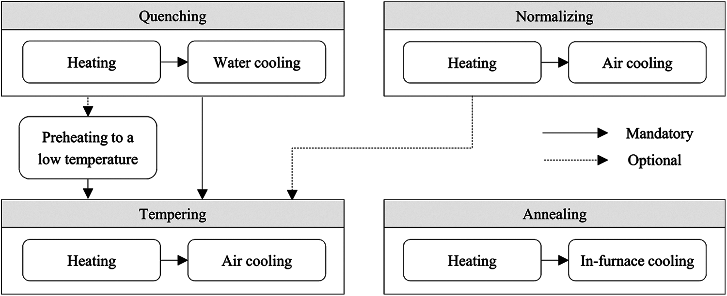
Figure 1: Heat treatment procedures
As previously mentioned, every workpiece has its own allowable heat treatment temperature range. Therefore, the workpieces constituting a batch cannot be heated together unless they have a common temperature subrange. As long as this temperature constraint is satisfied, workpieces that require different heat treatment techniques can be mixed together to form a batch. Once a batch is formed, its target temperature of heating is determined to be the lowest value of the common temperature subrange to save as much energy as possible. In addition to the temperature constraint, each batch must satisfy both weight and spatial constraints. The weight constraint is easy to check; the total weight of a batch must not exceed the capacity of its targeted furnace. However, checking the spatial constraints is much more complicated. All workpieces in a batch must be put together in a furnace following the respective loading rules for different types of shapes. These rules state that the ring- or disk-type workpieces can be stacked on top of each other, whereas the shaft type cannot be. Additionally, the shaft-type workpieces must be placed vertically to the furnace door because the support dies on the furnace floor are installed parallel to the door. When workpieces are placed in the water tank for cooling, there are similar rules for the shapes that must be followed. Our test bed factory is equipped with one water tank and seven heat treatment furnaces of various sizes.
Heat treatments are performed in various ways in different environments. Accordingly, numerous efforts have been made to develop methods for optimizing heat treatment scheduling. A previous study [7] dealt with scheduling the batch annealing process in steel coil production, where heating and cooling equipment are moved to the workpieces by cranes, while in most cases workpieces are moved to fixed equipment. Other previous studies [4,8,9] solved the problem of heat treatment scheduling in which workpieces were not grouped to form a batch but were sequentially loaded into a furnace. The common goal of these studies was to find an optimal order of loading. He et al. [10] presented a method for determining the weight of furnace charging to optimize energy efficiency, but made no mention of forming a specific batch that satisfies such weight constraints. It is also assumed that each furnace is specialized for a particular heat treatment technique, while any furnace can be used for any technique in our testbed factory. Lenort et al. [5] proposed a heuristic algorithm to form a batch to best exploit the weight capacity of the targeted furnace. However, the heat treatment process in Lenort et al. [5] is different from ours in that there is a pressing process between the heating and cooling stages. This research aims to form a batch heuristically depending on the predetermined order of pressing.
Despite being aimed at the steel casting industry, [2] proposed a heuristic algorithm for scheduling heat treatment furnaces. While the heat treatment process is similar to ours, this method does not attempt to optimize the schedule, but simply forms a batch heuristically by following the order of completion of the preceding process, respecting the priority given in advance and preferring larger workpieces. Wang et al. [3] proposed a multi-objective integer programming model to search for a batch schedule of the heat treatment process with minimum tardiness and energy consumption. The model adopts fuzzy logic to deal with uncertainties in processing times and energy costs. The energy cost of a batch is estimated to be the maximum of the energy costs of the individual workpieces constituting the batch, where a fuzzy triangular distribution represents the cost for each piece. In our study, both time and energy costs of a batch are estimated using cost models learned from process data collected using the IoT sensor network installed at our testbed factory. Wang et al. [3] is also different from our study in that there is only a single furnace, while in our test bed, there are many furnaces whose process costs must be individually estimated.
There are numerous studies [11–16] on batch-scheduling problems, not for heat treatment, but for other batch-machine manufacturing processes (e.g., glass, semiconductor, and aluminum manufacturing). These batch-scheduling problems assume that all jobs in a batch are completed simultaneously. In our problem, however, the completion time of heating for a given batch may differ for each of the workpieces in the batch because of their different holding periods. Tang et al. [17] proposed a dynamic programming algorithm to build a heating schedule with a minimum makespan for producing steel products called tube billets. While the workpieces should be grouped to form batches for heating, the type of problem solved in this work is called a semi-continuous batch-scheduling problem because the workpieces in a batch are put into and taken out of the furnace sequentially under the capacity constraint of a given furnace. The batch itself, unlike ours, has no size constraints. Sobottka et al. [1] proposed a simulation-based optimization method for scheduling parallel heat treatment furnaces with the objective of minimizing the energy cost and the space cost for storing the products while meeting the production deadlines. The problem is similar to ours in that heating and cooling are repeated multiple times and a batch should be composed of workpieces with the same heat treatment temperature. In this work, it is assumed that the information on the heat treatment temperature and the time taken for heating each workpiece is explicitly provided. The energy cost was estimated using the thermal mass constant and heat transmission coefficient appropriately determined for each furnace in advance. In contrast, the approach proposed in this paper does not assume that such information is explicitly provided. We build a decision tree based on historical data to determine a possible range of heat treatment temperatures for a given workpiece. We also learn cost models from the process data collected to predict the energy cost and the time taken for heating in a given furnace for a given batch. Finally, none of the previous works discussed in this section considered spatial constraints when configuring a batch.
This section describes the proposed method to search for an optimal heat treatment schedule that satisfies various constraints imposed on the batches of workpieces. Subsection 4.1 explains how we obtain the information necessary for constraint checking. Subsection 4.2 introduces the data-driven models used for predicting the costs of the heating and cooling processes. Subsection 4.3 describes the solution representation used in our evolutionary search algorithm together with the decoding method. Subsection 4.4 presents our objective function for evaluating candidate solutions during the search.
4.1 Obtaining Information Necessary for Constraint Checking
To determine whether a batch for a furnace satisfies all the required constraints, we should know the weight, shape, dimensions, and heat treatment temperature of each workpiece, as well as the size and weight capacity of the furnace. All information except the heat treatment temperature can be obtained from the enterprise resource planning (ERP) system of the testbed factory. The key factors affecting the desirable temperature range for heat treatment of a workpiece are the raw material of the workpiece, the physical properties (strength and hardness) of the end product requested by the customer, heat treatment temperature recommended by the customer, and heat treatment technique (quenching, normalizing, etc.) to be used. However, it is not easy to obtain rules for determining the temperature range for heat treatment from a human expert, as there are an overwhelming number of different cases. Our solution to this difficulty is to derive a decision tree by inspecting past process records of heat treatment. The data obtained from historical records have five input features: material code, heat treatment technique, target strength, target hardness, and heat treatment temperature recommended by the customer. The output value of each data point is the temperature range of the heat treatment, whose lower and upper bounds are the lowest and the highest heat treatment temperatures found in historical records, respectively.
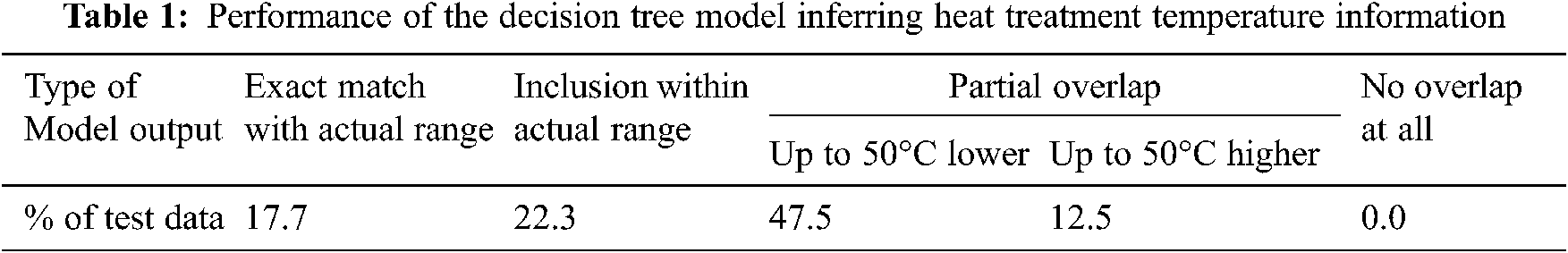
The dataset consisting of approximately 2,500 past heat treatment cases was divided into a training set and a test set with a ratio of 7:3. Fig. 2 shows the input and output of our decision-tree model learned from the training set. Since the purpose of learning is to summarize past data rather than make predictions, we turned off pruning to ensure that our decision tree was exactly fitted to the data with no training error. Nonetheless, the tree can be used, although not perfectly, to determine the heat treatment temperature of a workpiece with previously unseen requirements. If the heat treatment temperature recommended by the decision tree for a new product turns out to be unacceptable, we can add to the training data this new case with the right value of temperature range and relearn the tree. Tab. 1 shows the performance of our decision tree on the test set of approximately 750 cases. For approximately 40% of all test data, the temperature recommended by the decision tree agrees with the actual range. For the remainder, the recommended range overlaps with the actual range. We have not seen test data that show a completely different range than recommended.
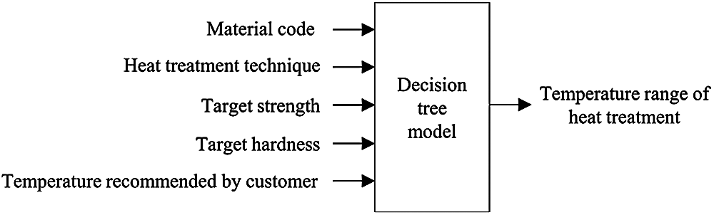
Figure 2: The input and output of the decision-tree for determining the heat treatment temperature
4.2 Data-driven Models for Cost Prediction
We use data-driven models based on an artificial neural network to predict the time and energy costs of heat treatment processes. These models are used to evaluate candidate solutions while searching for an optimal heat treatment schedule. Fig. 3 shows how the temperature changes with time during a typical heat treatment process in a heating furnace. Initially, the temperature continues to rise until it reaches the target temperature. After this heating period, the temperature is held constant until all workpieces are removed. The length of the holding period, or the holding time, varies from workpiece to workpiece. A workpiece can be removed from the furnace only after its predetermined minimum holding time has elapsed. Some workpieces are forced to remain in the furnace for longer than their minimum required holding time if the equipment for subsequent cooling is not ready. The value of the heating rate that is set at the beginning of heating determines the expected length of the heating period, or the heating time. The heating rate, defined as the amount of temperature increase per hour, is set depending on the target temperature of the heat treatment. However, the actual heating time is often significantly longer than the expected length because the furnaces are of different ages and sizes, and thus perform differently. Therefore, the heating time is predicted by the model learned from temperature data gathered from historical process records.
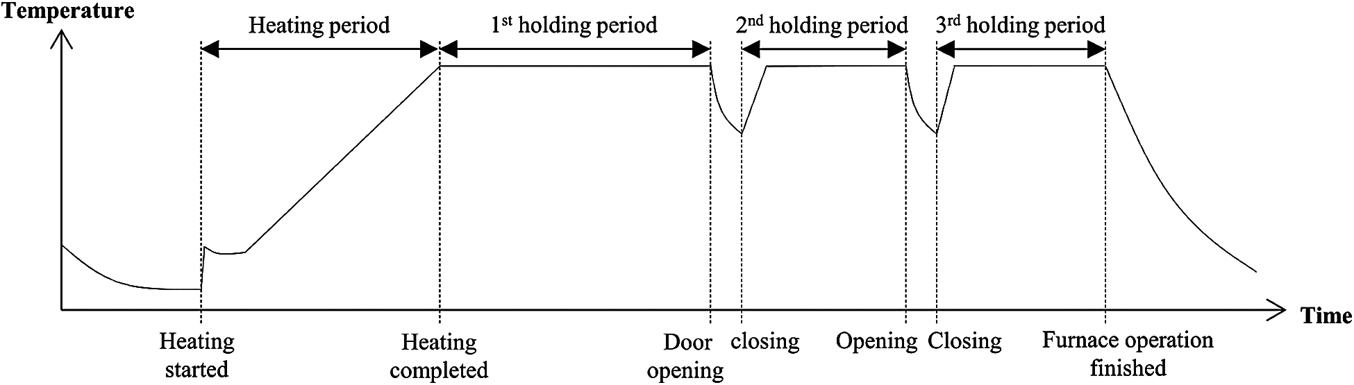
Figure 3: Temperature changes of a typical heat treatment furnace
The features used for learning the model to predict the heating time are the total weight of the batch, the maximum of the minimum required holding times of the workpieces, the heat treatment techniques to be used, the target temperature, the expected heating time calculated from the value of the heating rate setting, and the furnace ID. Note that a furnace can simultaneously accommodate workpieces requiring different heat treatment techniques, as long as their temperature ranges for heat treatment have a common subrange. Therefore, a batch may have workpieces that involve multiple heat-treatment techniques. We use k-bit binary encoding, where k is equal to the number of different heat treatment techniques available, and set the bits corresponding to the heat treatment techniques included in a batch. We also use binary encoding to represent the furnace ID. If we had sufficient training data, we would have built a separate model for each furnace. In addition to all of the previously mentioned features, the features for learning the model to predict the energy cost of a heating period include the predicted heating time. The mean absolute percentage errors (MAPE) of prediction observed by ten-fold cross-validation for heating time and energy cost were 8.2% and 16.3%, respectively.
As mentioned above, a workpiece should be held in a furnace longer than its minimum holding time if the subsequent cooling process cannot begin immediately. While the minimum holding time of a workpiece is determined using a simple formula that returns a value proportional to the thickness of the workpiece, the holding times in delayed cases are estimated by simulating the operations of heating furnaces and cooling equipment. The features used for learning the model to predict the energy cost of a holding period are the total weight of the batch, target temperature, estimated holding time, number of door openings, and furnace ID. The first holding period spans the time interval starting from the time at which heating is completed to the time of the first door opening to remove the workpiece with the minimum required holding time. After the door is closed, the second holding period lasts until the second door opening to remove the next workpiece for cooling. The number of door openings for the first holding period is zero, and that for the second period is one. In short, the number of door openings for the mth holding period must be m – 1. The number m is meaningful because a larger m implies a smaller number of remaining workpieces in the furnace, and thus the energy cost for holding would be lower. We would not have included this number as a feature if we knew which workpiece was taken out at each door opening because we would know the total weight of the workpieces remaining in the furnace. However, this information was not recorded in our testbed factory. The reason for including the furnace ID as a feature is the same as before; we do not have enough training data to build the model separately for each furnace. The MAPE of prediction observed using ten-fold cross-validation for the energy cost during holding was 15.2%. Finally, the time taken for cooling can be obtained from the rule in the field manual for each cooling technique used in our testbed factory.
4.3 Solution Representation and Decoding
We use the restricted tournament selection (RTS) algorithm [18] to search for an optimal heat treatment schedule. RTS is an evolutionary algorithm known to exhibit good performance by promoting population diversity [19,20]. Fig. 4 shows our representation of a candidate solution, where the chromosome is divided into three sections. The first and second sections contain the permutation of the IDs of the heat treatment jobs. The jobs in the first section are for tempering only, and those in the second section are for the remaining heat treatment techniques. The third section contains a binary code of length l, indicating the role of each furnace. Its ith value is 1 if furnace i is reserved for the jobs in the first section and 0 if in the second section. Furnaces are prioritized according to the order of their availability. A furnace is available if it turns idle after finishing the previous heat treatment task. The tempering jobs are separated from the remaining to promote energy efficiency. Since the temperature ranges for tempering are usually lower than those of other heat treatment techniques, a batch consisting only of tempering jobs is likely to have a common subrange at low temperatures. If tempering jobs are mixed with the jobs for different heat treatments, the resulting common subrange tends to be at higher temperatures because the temperature ranges of other techniques are likely to overlap with the upper part of the tempering ranges.
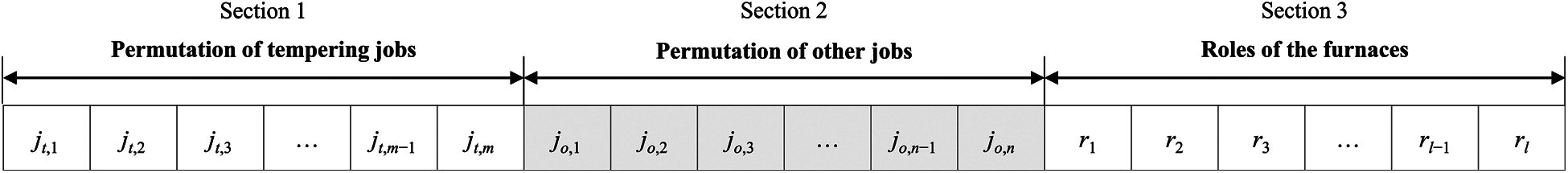
Figure 4: Representation of candidate solution
As a job corresponds to a heat treatment that a workpiece should go through, multiple jobs are generated for a single workpiece if multiple treatments are required. The multiple jobs for such a workpiece may belong to different sections depending on the type of treatment, while there exists a technical ordering constraint that should be followed among those jobs. The order of the jobs in a permutation represents the priority for being assigned to a batch for a furnace, which implies that a batch can consist only of the jobs in the same section. The decoding process of a permutation is the process of forming a batch with the jobs ready for treatment, which involves checking various constraints. As the first of such constraints, a job in a permutation cannot be assigned to a batch unless its preceding heat treatments, which are also jobs in the permutations, are already completed. How do we know when a job or heat treatment is completed? The answer can only be obtained by simulating the execution of the heat treatment schedule represented by a candidate solution. Therefore, we cannot but perform the decoding in parallel with the heat treatment simulation, as detailed below. Owing to the various representations used in a chromosome, different operators are applied to different sections when recombining two individuals. Partially matched crossover and swap mutation are used for the first and second sections, respectively. Uniform crossover and bit-flip mutation are used in the third section.
Fig. 5 shows the simulation procedure for assigning a batch to a furnace and then operating the furnace. This procedure is invoked for any furnace that has become idle but has not been assigned a batch. Although each call is made sequentially at the beginning following the order of the availability of the furnaces, they run in parallel for all furnaces. A batch b allocated to a furnace f by the batchAllocation function (Fig. 6), as described below, consists of ready jobs. Ready jobs are those that have had their preceding treatments completed or that do not require any prior heat treatment. An empty b indicates a batch allocation failure, which occurs in two situations: in the case where jobs remain to be done, f waits for a predetermined period and then keeps trying another batch allocation until successful hoping that some jobs may turn ready during waiting; and in the case where there are no more jobs, the procedure exits, and no further batch allocation are attempted for f. A furnace can be used for preheating any time after batch allocation is attempted but fails. However, a furnace under preheating operation can be preempted at any time by a new batch allocation. Here, the workpieces being preheated in it are transferred to other furnaces available for preheating. However, preemption is not allowed if no such furnace can be found.
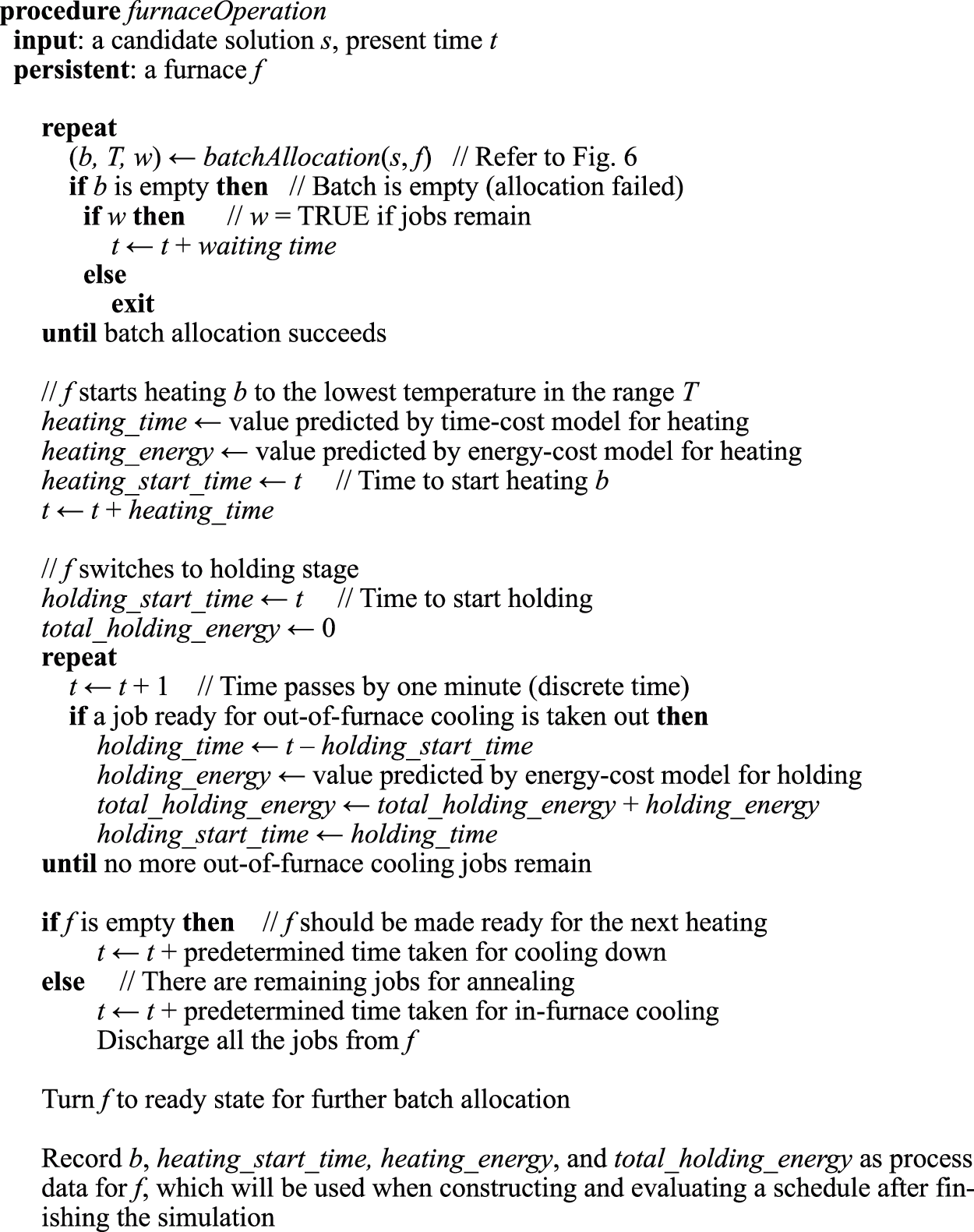
Figure 5: Procedure of the furnace operation
Once a batch is assigned, f starts heating batch b. The time and energy costs for heating are obtained from the cost models learned from historical data. After saving these values, the current time t is updated by adding the time taken for heating. Then, f switches to the holding stage in which the workpieces requiring out-of-furnace cooling (air or water cooling) are removed one after another. The time and energy costs for each holding period are obtained again from the cost models. When each workpiece is removed from f for cooling, the energy cost for the corresponding holding period is obtained from the relevant cost models. The workpieces requiring air cooling are removed from f immediately after their required holding periods are over. However, those requiring water cooling may have to remain in f longer than their minimum holding periods if the water tank is busy to cool other workpieces. After saving the relevant values, f switches to the final stage. If f is empty, it is naturally cooled to become ready for upcoming heating. If f still contains workpieces for annealing, scheduled cooling is required for in-furnace cooling. After all these steps, the furnace turns ready for the next batch allocation. The relevant data required for constructing and evaluating the heat treatment schedule are recorded before terminating the procedure. Among these, the start time of heating a batch is often adjusted heuristically during the construction of a schedule to save energy costs. For example, the holding time of a workpiece may be longer than necessary because the water tank for cooling is overloaded, and so is not readily available. This extended holding time may be reduced if the heating start time is delayed.
Fig. 6 presents the batchAllocation function, which is called from the furnaceOperation procedure. It returns a batch b allocated to the given furnace f, the range T of the heating temperature, and a flag w indicating whether there are jobs waiting for treatments. The function first checks the role of f by looking at the third section of a given candidate solution s, and then determines whether the permutation P in the first or second section should be decoded to form a batch. It is the batchFormation function (Fig. 7) that decodes the selected permutation P to form a batch b for f and to determine the temperature range T suitable for heating b. The batch b thus formed is checked to determine whether it can be allocated to f for heating. If b is large enough for f in size and weight, it can be allocated to f unless f contains some workpieces for preheating. If f is under preheating, the workpieces in it must be relocated to other furnaces before loading b to f. However, the allocation fails if relocation is impossible, in which case b is set to empty. When b is not sufficiently large to be allocated to f, allocation also fails. Here, it is necessary to check whether there are enough jobs waiting for the completion of their preceding heat treatment. If there are, w is set to TRUE to inform the furnaceOperation procedure that f should wait until more jobs become ready. If there are not enough waiting jobs, the role of f is switched so that batch allocation can be attempted by recursively calling batchAllocation to decode the job permutation in the other section of s.
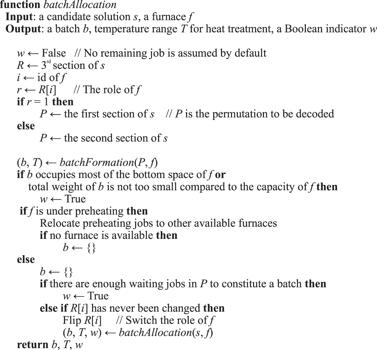
Figure 6: Function of batch allocation
Fig. 7 provides the pseudocode for the function of forming a batch for a given furnace f by decoding the given permutation P. The function scans P from left to right to find a job that has not been assigned to any batch but has finished its preceding heat treatment and whose temperature range overlaps with those of the workpieces currently in b. If a job satisfying all these conditions is identified, it is added to the current batch only when the weight and spatial constraints are satisfied. Whenever a job is added to the batch, the temperature range of the batch is updated to the overlapping range between its previous range and the range of the job added. Finding candidate jobs to be added to the batch and checking constraints continue until the last job in the permutation is reached. We use the Maximal Rectangles algorithm [6] together with the loading rules of our testbed factory to check whether the batch formed so far can be loaded into the furnace satisfying spatial constraints. The Maximal Rectangles algorithm is a 2D bin packing algorithm. With the workpieces turned to their rectangular bounding boxes, we use this algorithm to find the best place to put workpieces in the bottom area of the given furnace. The loading rule is used to stack a workpiece on top of another workpiece placed at the bottom.
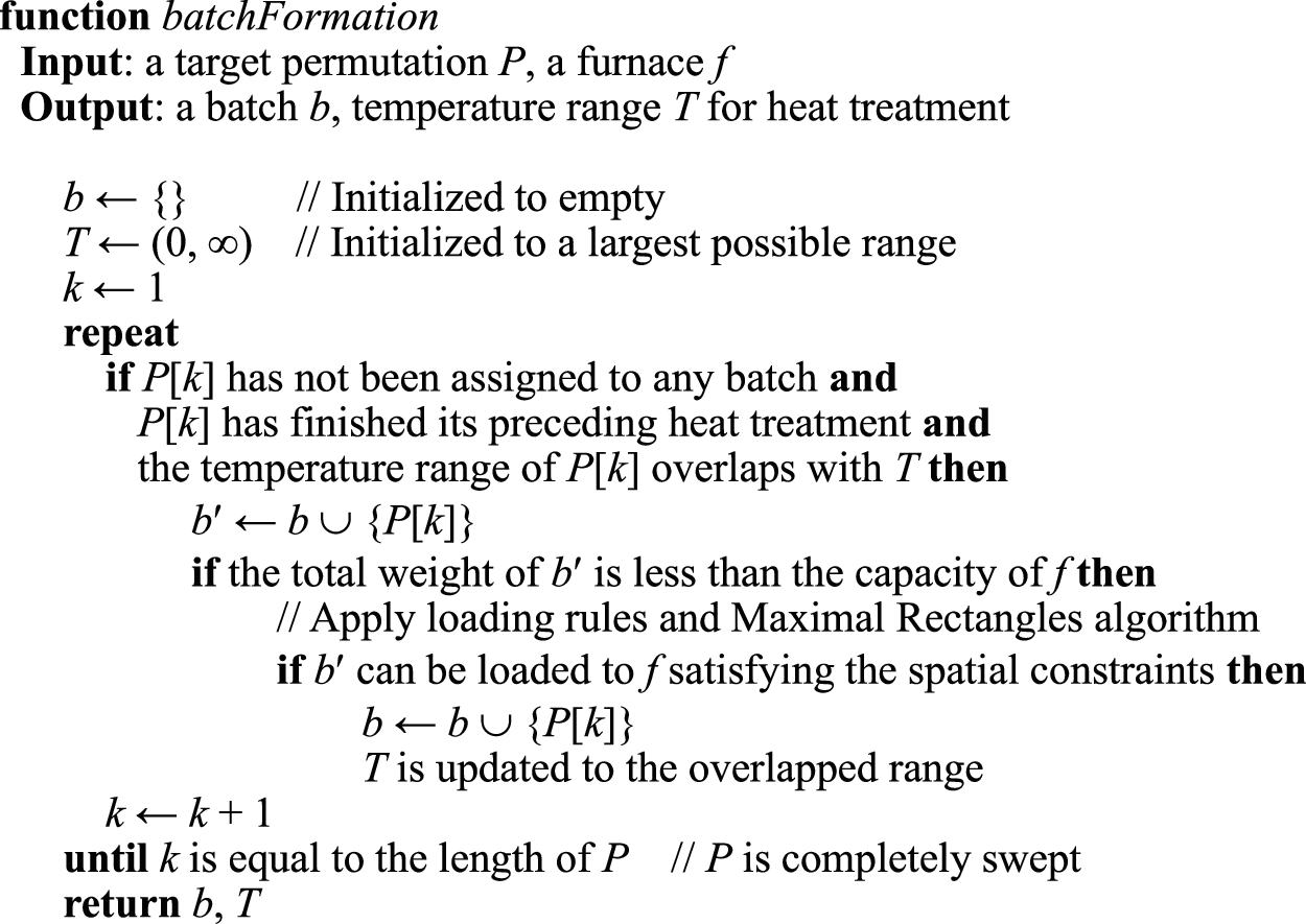
Figure 7: Function of forming a batch for a given furnace
We take a rolling-horizon approach to the search for an optimal heat treatment schedule. Given a horizon of a predetermined length, which usually spans several days, our algorithm searches for an optimal schedule for the jobs within a horizon but executes only the jobs scheduled for the first day of the horizon. After this day, the algorithm keeps rescheduling with the horizon shifted or rolled by one day. The jobs for a horizon are collected from a long-term list of jobs, giving higher priorities to those with earlier deadlines. A good schedule for a given set of jobs is the one that achieves high productivity with low energy consumption. The objective function is as follows:
where T is the makespan, W is the total weight of the processed workpieces, E is the total energy consumption per ton, D is the tardiness, and O is the total amount of overtime spent on air cooling. The makespan T is the period starting from the beginning of the first heat treatment until the end of all heat treatment jobs. The total weight T can vary under a fixed horizon because of the uncertainty in forming batches during scheduling. A smaller T with a larger W corresponds to a higher productivity. Since the objective function is for minimization, the term W is made negative. E is calculated by dividing the total energy consumption by the total weight W. D and E are the penalty terms for punishing constraint violations. While all hard constraints are dealt with when a solution is decoded as explained in Subsection 4.3, these two soft constraints are left untouched. Violations of soft constraints are not strictly prohibited but should be minimized. D is calculated as the square root of the mean of the squares of the delays of individual jobs. O is used for normalizing jobs that require subsequent quenching. The time spent for air cooling should not exceed the predetermined period, whenever possible, to ensure product quality.
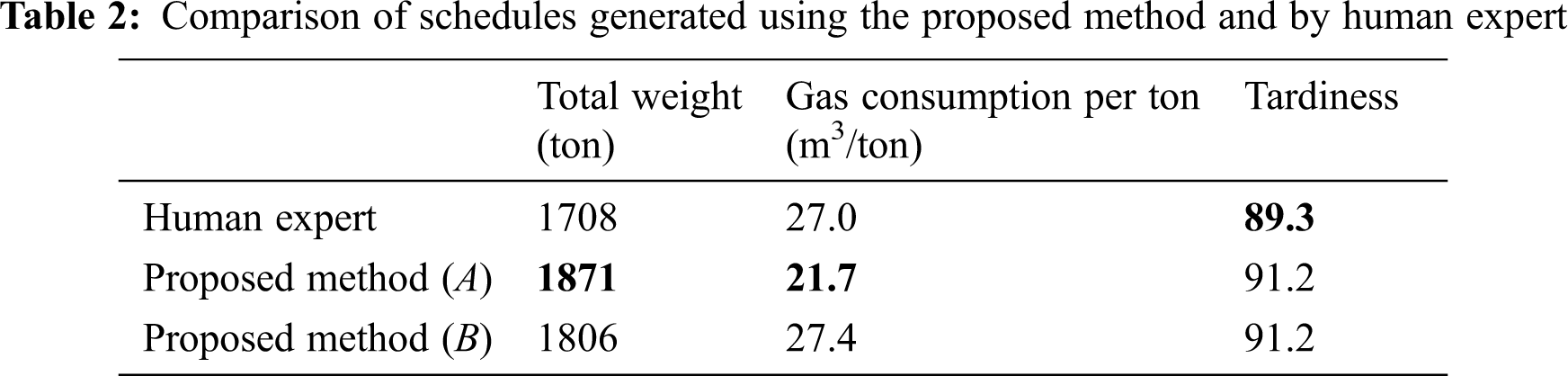
We conducted simulation experiments to compare the qualities of the schedules generated using our method with those generated by a human expert in our testbed factory. The human-generated schedules were taken from a production record of a recent period of six days. Our schedules to be compared were generated by applying our rolling-horizon scheduling method to the same period, where the length of the horizon is empirically set to five days. More specifically, a schedule for a five-day horizon was built, but only a part for the first day was executed, and then this rolling-horizon scheduling and execution were repeated six times for those six days in the period. Since our schedules could not be executed in the testbed factory, we created a virtual factory, i.e., a factory emulator, to simulate both ours and the expert’s schedules. The cost models used in the virtual factory and those used in our schedule optimization are basically the same, except that the outputs of the latter models are blurred by adding Gaussian noises to mimic the erroneous predictions that occur in real situations. To add e% approximate mean absolute error to the model output o, we took a random value r from a zero-mean, unit-variance Gaussian distribution, and then we either added or subtracted o(e + r)/100 to o with the probability of 0.5. The level of noise we added in our first experiment (Tab. 2) was approximately 10%. Because of the random noise added, the results differ from simulation to simulation.
Tab. 2 compares the quality of the schedules generated by different methods. The values given are the averages of the results of ten simulations. The weights in the objective function of our optimization algorithm are empirically set as w1 = w4 = w5 = 1, w2 = 10, and w3 = 100. As can be seen in the table, two versions of our method were tested. Version A is described in Section 4, where tempering jobs form a batch exclusively. Version B is different from version A in that it allows tempering jobs to be mixed with other types of heat treatment jobs when forming a batch. We can see that version A dominates version B in every aspect. Note that the total weight processed using our method (version A) is almost 10% larger than that in the results by the human expert, whereas the improvement in the energy consumption by our method is approximately 24%, which is significant. However, our method is slightly worse than the human expert in keeping the deadlines, as shown by the slightly higher value of tardiness in the table. The table does not show any results regarding another soft constraint on air cooling time for normalizing jobs, as no violation has been observed with any methods.
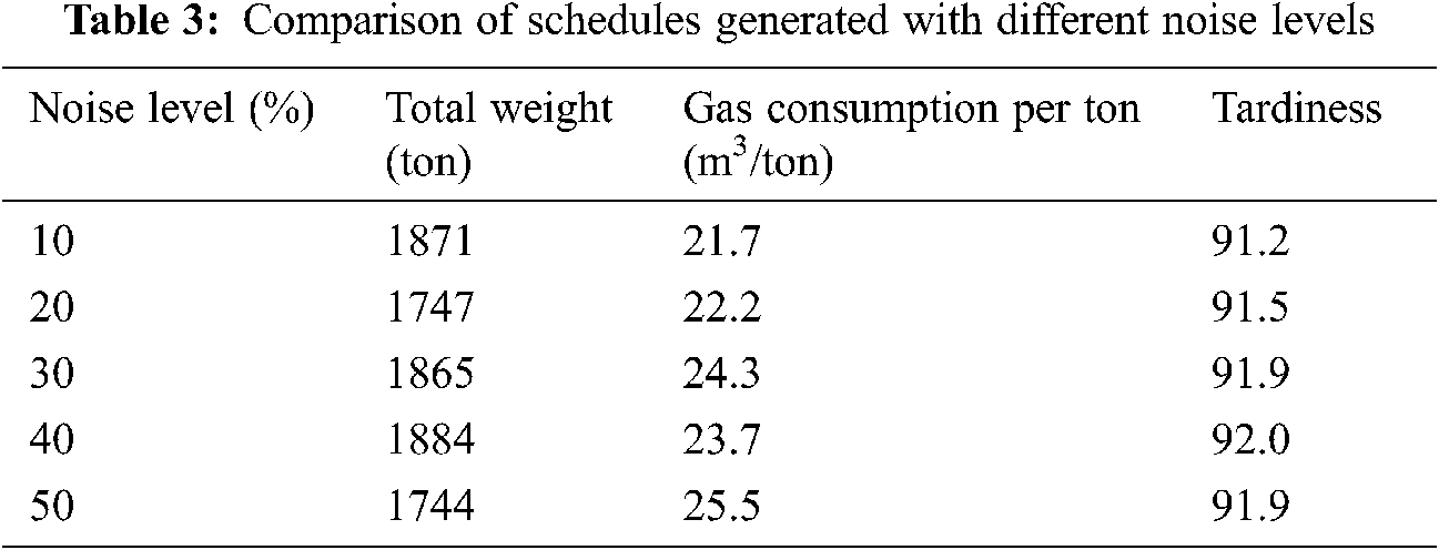
We continued the experiments described above to see the sensitivity of our optimization algorithm to the prediction accuracy of the data-driven models employed. Here, we increased the noise level by 10% from 10% to 50%. The noise was added only to the outputs of the models used in our optimization algorithm, while the models used in the factory emulator were kept untouched. Tab. 3 shows the quality of the schedules obtained using our method (version A) with different levels of added noise. The numbers in the table are the average results of ten simulations. Both the total weight processed and tardiness showed no particular trend toward the increase of the noise level. However, the energy consumption gradually increased with the noise. One notable point is that the energy consumption was still lower while the total weight processed was larger than that of the human expert’s schedule (Tab. 2) even at the noise level of 50%. This suggests us that we may use data-driven models for schedule optimization without too much concern to their prediction accuracy.
We solved the problem of heat treatment scheduling for an energy-intensive hot press forging factory with the objectives of maximizing productivity and minimizing energy consumption. A major difficulty in solving this problem is the formation of batches of heat treatment jobs under various constraints. The approach we took to cope with this difficulty is to encode candidate solutions as a permutation of heat treatment jobs and then to have all hard constraints satisfied during the decoding process of forming a batch. However, because of constraints such as the one in which a job can be included in a batch only if all its preceding heat treatments are over, the decoding process cannot but be performed in parallel with the simulation of the partially decoded results. An advantage of this approach is that it allows our optimization algorithm to easily find solutions. Although there are methods for constraint satisfaction search that deal with the constraints during the search, they often face difficulty in finding a feasible solution. One of our future works will be to develop a constraint satisfaction search algorithm for our heat treatment scheduling problem and see whether it outperforms the proposed algorithm.
In this paper, we showed that the schedules obtained using our method achieve higher productivity with lower energy costs than those obtained by human experts, but only through simulation experiments. Since our virtual factory employs the same cost models used for our optimization search, the resulting performance shown could be biased in favor of our method compared to the field expert. However, through additional experiments in which the cost models used in the optimization search are deliberately degraded, we have seen that our approach of adopting data-driven models is not too sensitive to the prediction accuracies of those models. We suspect that model errors do not significantly deteriorate the performance of the schedule optimizer in ranking the schedules by their quality during the search. When, for example, the real energy cost for heating batch A is lower than that of batch B, A is rarely estimated to be worse than B by erroneous models even though their individual estimates are not quite correct. However, we need further study to clarify the effect of prediction errors of the data-driven models to the performance of schedule optimizer.
Funding Statement: This work was supported by the Korea Institute of Energy Technology Evaluation and Planning (KETEP) and the Ministry of Trade, Industry & Energy (MOTIE) of the Republic of Korea (No. 20182020109660), and by the Institute of Information & Communications Technology Planning & Evaluation (IITP) grant funded by the Korean government (MSIT) (No. 2020-0-01451, Artificial Intelligence Convergence Research Center [Pusan National University]).
Conflicts of Interest: The authors declare that they have no conflicts of interest to report regarding the present study.
1. T. Sobottka, F. Kamhuber and B. Heinzl, “Simulation-based multi-criteria optimization of parallel heat treatment furnaces at a casting manufacturer,” Journal of Manufacturing and Materials Processing, vol. 4, no. 3, pp. 94, 2020. [Google Scholar]
2. M. Mathirajan, V. Chandru and A. I. Sivakumar, “Heuristic algorithms for scheduling heat-treatment furnaces of steel casting industries,” Sadhana, vol. 32, no. 5, pp. 479–500, 2007. [Google Scholar]
3. J. Wang, F. Qiao, F. Zhao and J. W. Sutherland, “Batch scheduling for minimal energy consumption and tardiness under uncertainties: A heat treatment application,” CIRP Annals, vol. 65, no. 1, pp. 17–20, 2016. [Google Scholar]
4. A. Baykasoğlu and F. B. Ozsoydan, “Dynamic scheduling of parallel heat treatment furnaces: A case study at a manufacturing system,” Journal of Manufacturing Systems, vol. 46, no. 3, pp. 152–162, 2018. [Google Scholar]
5. R. Lenort, R. Klepek and A. Samolejová, “Heuristic algorithm for planning and scheduling of forged pieces heat treatment,” METALURGIJA, vol. 51, no. 2, pp. 225–228, 2012. [Google Scholar]
6. J. Jylänki, “A thousand ways to pack the bin–A practical approach to two-dimensional rectangle bin packing,” [Online]. 2010. Available: http://clb.demon.fi/files/RectangleBinPack.pdf. [Google Scholar]
7. S. Moon and A. N. Hrymak, “Scheduling of the batch annealing process – deterministic case,” Computers & Chemical Engineering, vol. 23, no. 9, pp. 1193–1208, 1999. [Google Scholar]
8. T. Al-Kanhal, “An intelligent manufacturing system for heating treatment scheduling,” Ph.D. dissertation. Brunel University School of Engineering and Design, England, 2010. [Google Scholar]
9. Q. Cheng, C. Liu, H. Chu, Z. Liu, W. Zhang et al., “A new multi-objective hybrid flow shop scheduling method to fully utilize the residual forging heat,” IEEE Access, vol. 8, pp. 151180–151194, 2020. [Google Scholar]
10. F. He, Z. Wang, K. Shen and R. Jia, “Research on scheduling of furnace loading quality maximization in forging heat treatment process,” IOP Conference Series: Materials Science and Engineering, vol. 562, no. 1, pp. 012152, 2019. [Google Scholar]
11. Y. Ikura and M. Gimple, “Efficient scheduling algorithms for a single batch processing machine,” Operations Research Letters, vol. 5, no. 2, pp. 61–65, 1986. [Google Scholar]
12. S. Wang, M. Liu, F. Chu and C. Chu, “Bi-objective optimization of a single machine batch scheduling problem with energy cost consideration,” Journal of Cleaner Production, vol. 137, no. 3, pp. 1205–1215, 2016. [Google Scholar]
13. L. Mönch, J. W. Fowler, S. Dauzère-Pérès, S. J. Mason and O. Rose, “A survey of problems, solution techniques, and future challenges in scheduling semiconductor manufacturing operations,” Journal of Scheduling, vol. 14, no. 6, pp. 583–599, 2011. [Google Scholar]
14. Q. Guo, L. Tang, J. Liu and S. Zhao, “Continuous-time formulation and differential evolution algorithm for an integrated batching and scheduling problem in aluminium industry,” Int. Journal of Production Research, vol. 59, no. 10, pp. 3169–3184, 2021. [Google Scholar]
15. B. Ogun and Ç. Alabas-Uslu, “Mathematical models for a batch scheduling problem to minimize earliness and tardiness,” Journal of Industrial Engineering and Management, vol. 11, no. 3, pp. 390–405, 2018. [Google Scholar]
16. R. Yusriski, B. Astuti, T. A. Samadhi and A. H. Halim, “Integer batch scheduling problems for a single-machine to minimize total actual flow time,” Procedia Manufacturing, vol. 2, pp. 118–123, 2015. [Google Scholar]
17. L. Tang and Y. Zhao, “Scheduling a single semi-continuous batching machine,” Omega, vol. 36, no. 6, pp. 992–1004, 2008. [Google Scholar]
18. G. R. Harik, “Finding multimodal solutions using restricted tournament selection,” in Proc. of the Int. Conf. on Genetic Algorithms (ICGAPittsburgh, PA, USA, pp. 24–31, 1995. [Google Scholar]
19. B. Sareni and L. Krähenbühl, “Fitness sharing and niching methods revisited,” IEEE Transactions on Evolutionary Computation, vol. 2, no. 3, pp. 97–106, 1998. [Google Scholar]
20. J. H. Hong and K. R. Ryu, “Simulation-based multimodal optimization of decoy system design using an archived noise-tolerant genetic algorithm,” Engineering Applications of Artificial Intelligence, vol. 65, no. 3, pp. 230–239, 2017. [Google Scholar]
 | This work is licensed under a Creative Commons Attribution 4.0 International License, which permits unrestricted use, distribution, and reproduction in any medium, provided the original work is properly cited. |