DOI:10.32604/iasc.2022.019555
| Intelligent Automation & Soft Computing DOI:10.32604/iasc.2022.019555 | |
| Article |
Dynamic Sliding Mode Backstepping Control for Vertical Magnetic Bearing System
1Graduate School of Engineering Science and Technology and Department of Electrical Engineering, National Yunlin University of Science and Technology, 64002, Yunlin, Taiwan
2Chunghwa Telecom Laboratories, Taoyuan City, 32661, Taiwan
3Universal Scientific Industrial Co., Ltd., Taiping Road, 54261, Taiwan
*Corresponding Author: Wei-Lung Mao. Email: wlmao@yuntech.edu.tw
Received: 17 April 2021; Accepted: 02 September 2021
Abstract: Electromagnets are commonly used as support for machine components and parts in magnetic bearing systems (MBSs). Compared with conventional mechanical bearings, the magnetic bearings have less noise, friction, and vibration, but the magnetic force has a highly nonlinear relationship with the control current and the air gap. This research presents a dynamic sliding mode backstepping control (DSMBC) designed to track the height position of modeless vertical MBS. Because MBS is nonlinear with model uncertainty, the design of estimator should be able to solve the lumped uncertainty. The proposed DSMBC controller can not only stabilize the nonlinear system under mismatched uncertainties, but also provide smooth control effort. The Lyapunov stability criterion and adaptive laws are derived to guarantee the convergence. The adaptive scheme that may be used to adjust the parameter vector is obtained, so the asymptotic stability of the developed system can be guaranteed. The backstepping algorithm is used to design the control system, and the stability and robustness of the MBS system are evaluated. Two position trajectories are considered to evaluate the proposed method. The experimental results show that the DSMBC method can improve the root mean square error (RMSE) by 29.94% compared with the traditional adaptive backstepping controller method under different position tracking conditions.
Keywords: Magnetic bearing system (MBS); Lyapunov stability; dynamic sliding backstepping control (DSMBC) algorithm; adaptive laws; model uncertainty
Dating back to 1842, it was first proposed to use permanent magnets or fixed current electromagnets alone. No matter how they were configured, it was impossible to suspend a magnetically guided object stably in midair, so it was necessary to find ways to better stabilize the operation. The active magnetic bearing was first produced in 1937 [1,2]. The MBS have many advantages over mechanical and hydrostatic bearings. These include zero frictional wear and efficient operation at extremely high speeds. In addition, they are considered an ideal choice for clean environments as they do not require lubrication. MBS are used in many applications, such as energy storage flywheels, high-speed turbines, compressors, pumps and jet engines. Compared with other bearings, magnetic bearings have many advantages [3], as follows: (1) It has almost no rotation resistance and the rotor speed can be much higher than other bearings; (2) They do not require complex lubrication or pneumatic system and can save space; (3) They have a long service life and low maintenance cost; (4) They can avoid the friction-induced noise; (5) They can be applied to special working environment such as under extremely low temperature or high vacuum; (6) They can provide the required rigidity through active control and effectively restraining the vibration problem caused by high-speed operation. Because of the advantages mentioned above, the magnetic floating bearings have been widely used in many fields.
In recent years, several researches have been devoted to the development of magnetic floating bearings [4]. Although many studies have determined the magnetic circuit structure and mechanical structure design of magnetic floating bearings, few researchers have analyzed and studied the nonlinear dynamic characteristics of the magnetic bearing system (MBS). Besides, two estimator based nonlinear controllers [5,6] have been proposed, which are used to estimate the total uncertainty of parameter variations and external disturbances in real time. The design of backstepping control [6,7] cannot respond to the input signals effectively, so it should be combined with the adaptive estimator [8] to estimate the unknown parameters of the system. In the self-tuning controller, the parameters are adapted and the estimated parameters are provided to the controller to solve the nonlinear problem of the MBS. The adaptive backstepping controller [9] can perform better steady-state response by using an estimation system with adaptive rules.
This research paper promotes the application of dynamic sliding mode backstepping control (DSMBC) for the MBS [10]. The slip line from the sliding mode control is used to estimate the total uncertainty of the system. The slope of the sliding line tends to make the coming speed faster, so that the response is compensated in time. Moreover, the estimated values are more effective to reach the accurate values. In this case, the system produces better results than the backstepping control. The Lyapunov function is used in the backstepping control to guarantee the convergence of the position tracking error. Two height position tracking is considered and tested. The simulation and experimental results demonstrate that the developed controller provides better tracking performance in the respect of model uncertainty.
The rest of this paper is structured as follows. Section II introduces the construction of the MBS and system model. In Section III, the dynamic sliding backstepping control is designed and analyzed. Section IV provides the experimental results. Finally, in Section V, conclusions are drawn.
2 Magnetic Bearing System Architecture
The structure of MBS is illustrated in Fig. 1. The system consists of a permanent magnet part and an electromagnet part. The magnetic bearing can float in the air when the electromagnet is electrified. The output current can reduce the power consumption to better alleviate the power required when the magnetic bearing position moves near the center. After comparing the command signal with the height signal feedback, the error signal is sent to the power amplifier through the controller operation. Furthermore, the voltage of the controller is transformed into electric current by a power amplifier and sent to an electromagnet to produce magnetic force. After the magnetic bearing can be suspended in the air, the height information is measured using an infrared sensor. The servo motor is used as the load platform, through which the load is added to complete the experiment. According to the Newton’s laws of motion, the dynamic system model is given by
where
where
where
The dynamic system can be written as
where
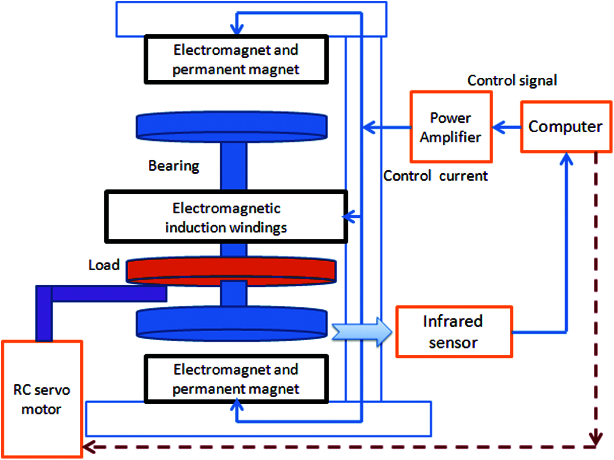
Figure 1: The structure of MBS
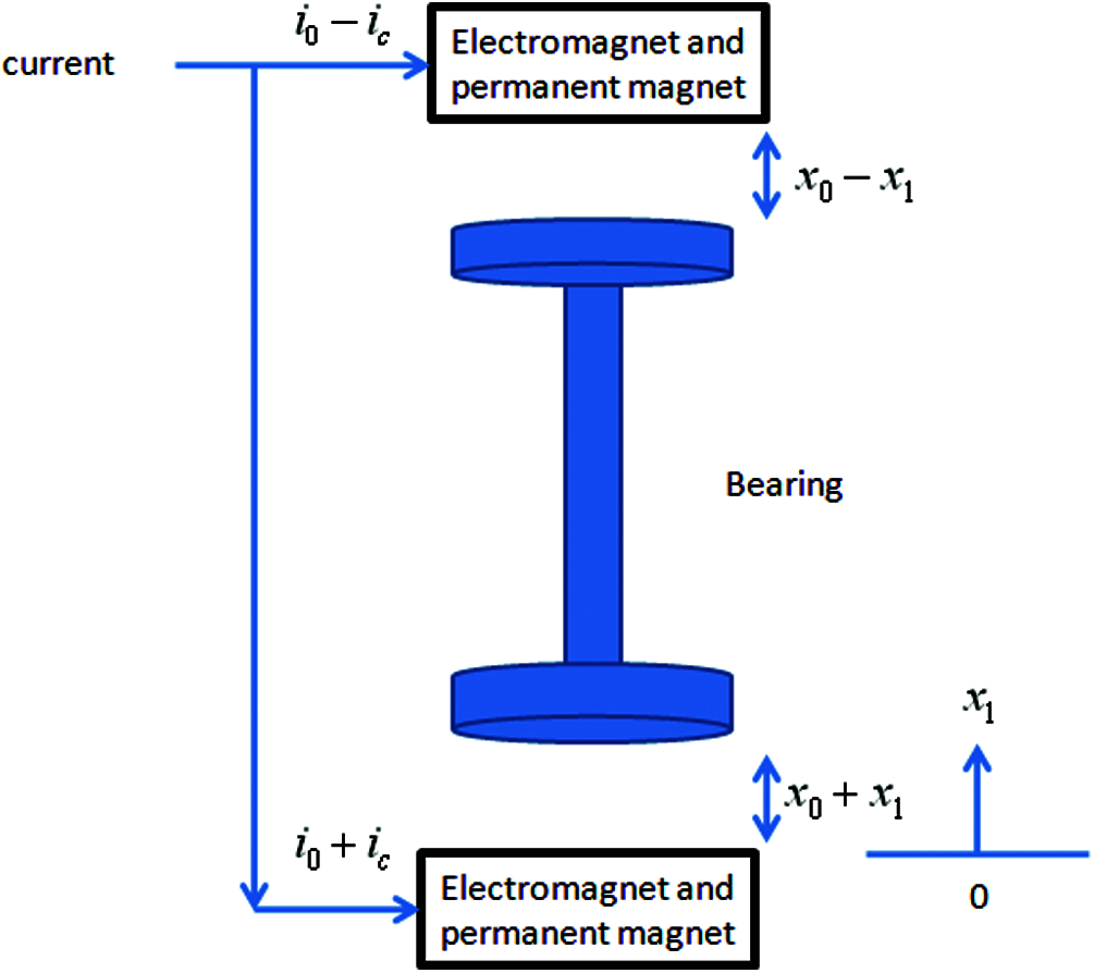
Figure 2: The electric currents and the positions of magnetic bearing
3 Proposed Dynamic Sliding Backstepping Control
3.1 Conventional Adaptive Backstepping Control
The MBS can be considered as a general second-order nonlinear system.
where
where
The stability function is defined as
where c1 is a positive constant. The variable
where
The difference between the actual value of the total uncertainty and the estimated value of the total uncertainty is given as
The continuous Lyapunov function is defined as
The time derivative of function
The second Lyapunov function is selected as
where r is a positive constant. After differentiation operation, it can be expressed as
The ideal control input
where
Substituting Eqs. (16) and (17) into Eq. (15), which can be represented as
By using the control law, the state can always approach the sliding surface and hit it. The asymptotic stability of the system can be guaranteed.
3.2 Proposed Dynamic Sliding Mode Backstepping Control
The DSMBC method is derived and developed in the MBS system. The tracking error is defined as
The stability function can be given by
where
where
where E is the actual value of the total set uncertainty. The error parameter of
where
The candidate Lyapunov function is given by
The time derivative of the Lyapunov function is
The second Lyapunov function can be written as
where
The ideal control law is defined as
where
Substituting Eqs. (29), (30) and (31) into Eq. (28), we obtain
If
with
Integrating the above equation with respect to time, resulting in
Because
The experimental results show the control capability of the developed algorithm for MBS. In this study, two types of control methods are compared. They are (a) the adaptive backstepping control method, (b) the proposed DSMBC method. Fig. 3 illustrates the experimental setup of the MBS equipment.
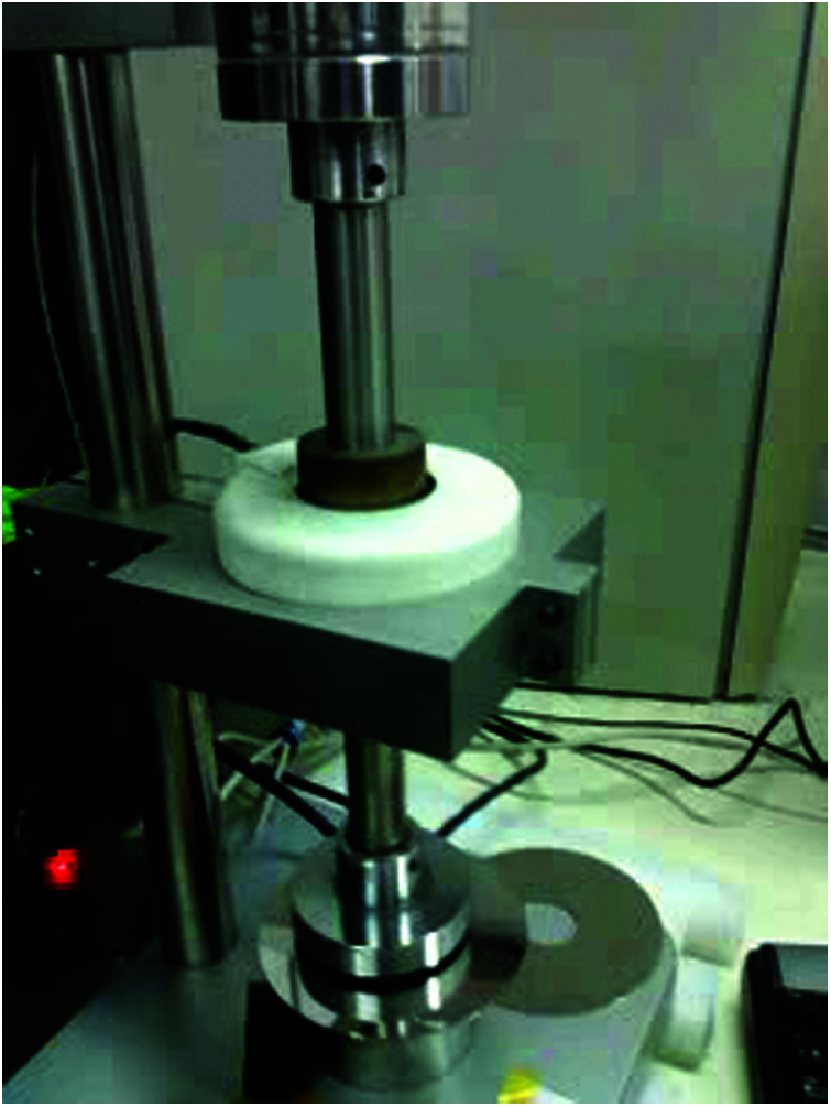
Figure 3: A photograph of the MBS system
Fig. 4 describes a block diagram of an adaptive backstepping control system. The MBS system with uncertainties is considered and analyzed. An error estimator is designed to estimate the system with unknown parameters. The estimator can modify the parameters according to the signal fed back to the system. It can also provide the estimated parameters to the controller on-line and calculate the estimated values of the parameters. The adaptive estimation scheme and backstepping control are used to solve the nonlinear problem of MBS. The adaptive backstepping control can keep the robustness of the system when the parameters of the system change or external disturbance occurs.
The system block diagram of the proposed DSMBC of the magnetic bearing is shown in Fig. 5. After the height command is obtained from the system, the controller can send the control command, and know the bearing system’s height and the calculation error subtracted by command. Then, the output of the bearing system enters the control card to calculate the error adjustment sliding mode control to estimate the uncertainty. After adjustment, it enters the control card operation until the command is chased. The controller tends to be based on step-return control and cooperates with the sliding. The model can estimate the uncertainty, where we adjust the parameter
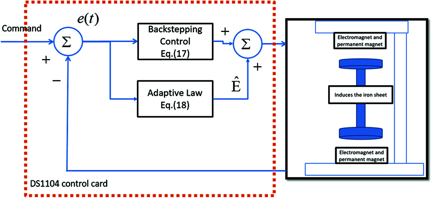
Figure 4: The system structure of adaptive backstepping controller
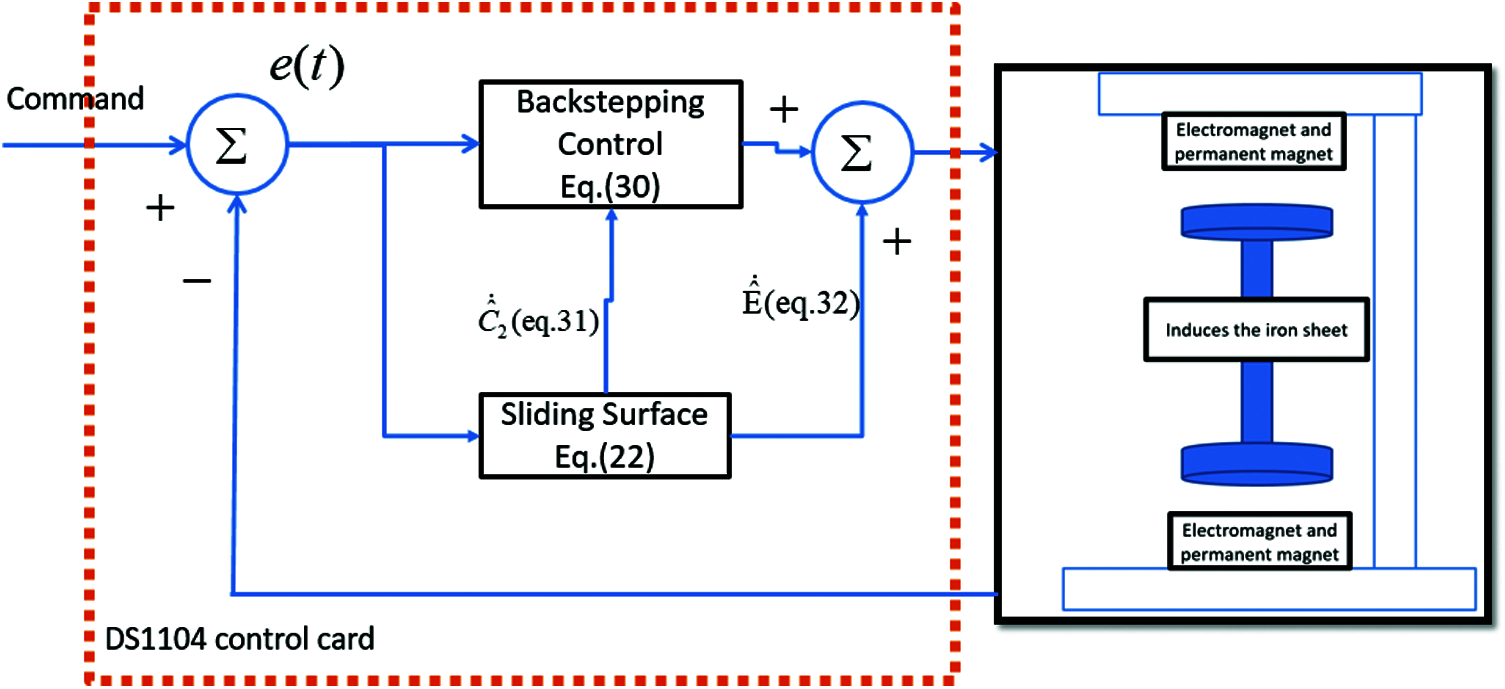
Figure 5: The system structure of dynamic sliding mode backstepping controller
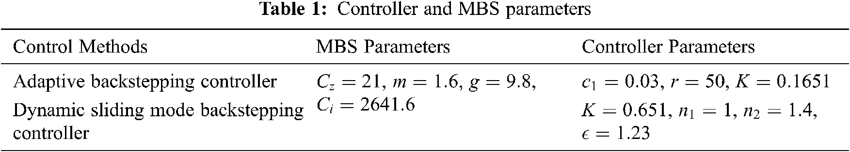
Tab. 1 lists the controller and MBS parameters in this research. The parameters were determined according to the rule of thumb to achieve better transient and steady-state responses under simulated and experimental conditions, considering the requirements of stability.
The simulation results using adaptive backstepping control method and the proposed DSMBC method were obtained and compared to verify the control performance.
In Fig. 6, the output response of command height is 2.5 mm, and an additional external load of 0.3 A is added at

Figure 6: The simulation response of 2.5 mm command height. An additional external load of 0.3 A is added at

Figure 7: The simulation response of 2.5 mm height command during
As shown in Fig. 7, the adaptive backstepping control has a faster transient response, as illustrated in Fig. 7a. However, the DSMBC method achieves the robustness performance under difference inputs and load conditions. The amount of control increases immediately after the height command changes, see Fig. 7c. Meanwhile, in Fig. 7d, the DSMBC also outperforms the adaptive backstepping control for estimation comparison. It can be seen that the DSMBC method performs better in real-time compensation and robustness tracking regardless of the height command and load disturbance.
To verify the practicality of the proposed DSMBC system, the experimental tests were performed and demonstrated. Fig. 8 depicts that the height command is set as 2.5 mm during

Figure 8: The experimental responses of 2.5 mm height command. An additional external load of 0.3 A is added at
Fig. 9a illustrates the height position response, and the error responses are shown in Fig. 9b. Fig. 9c presents the control input signals, and Fig. 9d depicts the estimated uncertainty responses. During the development of the proposed control method, the height error can be effectively reduced to within 1.1 s. The proposed DSMBC controller guarantees the asymptotic stability and exhibits better tracking capability.

Figure 9: The experimental responses of height command of 2.5 mm during
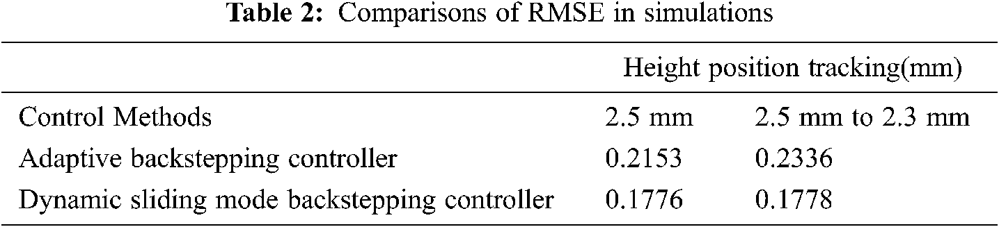
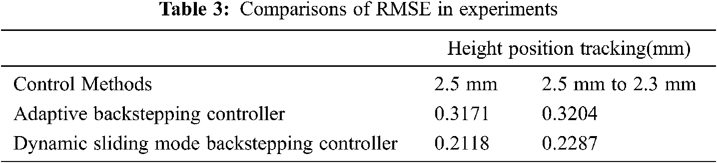
Tabs. 2 and 3 give the calculation results of root mean square error (RMSE). The RMSE performance index is defined as follows
where
Tabs. 2 and 3 clearly demonstrate that the DSMBC method is superior to the dynamic sliding backstepping schemes under all operational conditions because its energy control input is considered in our design. Thus, the experimental results can conclusively establish the regulation ability, dynamic tracking capability and robustness of the proposed adaptive method in a wide speed range.
The DSMBC method was successfully developed and used for vertical MBS in height tracking applications. The dynamic model of the MBS system was built by referring to the nonlinear characteristics, and the estimate functions of these nonlinear factors were proposed and applied to the equivalent control law of sliding mode control. The control system was designed, using the backstepping algorithm, and the stability of the MBS system was analyzed. Based on the Lyapunov theorem, the adaptive control law can be obtained and utilized for height position control application. The proposed DSMBC method achieves better tracking capability in real-time compensation and robustness tracking, and is not affected by height command and load disturbance. Two height trajectories are simulated and experimented to illustrate the robustness of the proposed system. Compared with the conventional adaptive backstepping method, the proposed DSMBC control system demonstrates more accurate performance, showing 20.70% improvement of RMSE in simulations and 29.94% improvement of RMSE in experiments. In the future, our goal is to establish a microcontroller or DSP platform, so that the proposed DSMBC method can be better implemented and widely used in industrial applications.
Acknowledgement: The authors thank TopEdit (www.topeditsci.com) for its linguistic assistance during the preparation of this manuscript.
Funding Statement: The authors would like to extend their deepest gratitude to the Ministry of Science and Technology of the Republic of China, Taiwan, for the financial support to this research under Contract No. MOST 110-2221-E-224-049 -, MOST 109-2221-E-224-024 -, and MOST 108-2731-M-224-001 -.
Conflicts of Interest: The authors Wei-Lung Mao, Yu-Ying Chiu, Chao-Ting Chu, Bing-Hong Lin, Jian-Jie Hung declare that they have no conflicts of interest to report regarding the present study.
1. S. Xu and J. Fang, “A novel conical active magnetic bearing with claw structure,” IEEE Transactions on Magnetics, vol. 50, no. 5, pp. 971–981, 2014. [Google Scholar]
2. B. Han, S. Zheng, X. Wang and Y. Qian, “Integral design and analysis of passive magnetic bearing and active radial magnetic bearing for agile satellite application,” IEEE Transactions on Magnetics, vol. 48, no. 6, pp. 1959–1966, 2012. [Google Scholar]
3. T. Sato and Y. Tanno, “Magnetic bearing having PID controller and discontinuous controller,” IEEE Int. Conf. on Industrial Electronics, pp. 2121–2125, 1993. [Google Scholar]
4. Z. Yi and L. Quan, “Improved adaptive filtering application based on DSP for active magnetic bearing system,” in 8th Int. Conf. on Signal Processing, 2006. [Google Scholar]
5. J. J. E. Slotine and W. Li, “Part II: Nonlinear Control Systems Design,” in Applied Nonlinear Control. Englewood Cliffs, NJ: Prentice-Hall, pp. 191–307, 1991. [Google Scholar]
6. D. Chwa, “Tracking control of differential-drive wheeled mobile robots using a backstepping-like feedback linearization,” IEEE Transactions on Systems, Man, and Cybernetics - Part A: Systems and Humans, vol. 40, no. 6, pp. 1285–1295, 2010. [Google Scholar]
7. S. Drid, M. Tadjine and M. S. Nait-Said, “Robust backstepping vector control for the doubly fed induction motor,” IET Control Theory & Applications, vol. 1, no. 4, pp. 861–868, 2007. [Google Scholar]
8. W. Li, Y. Jing, G. M. Dimirovski and X. Liu, “Robust nonlinear control of TCSC for power system via adaptive backstepping design,” Proc. of IEEE Conf. on Control Applications, 2003. [Google Scholar]
9. S. Sivrioglu, “Adaptive backstepping for switching control active magnetic bearing system with vibrating base,” IET Control Theory & Applications, vol. 1, no. 4, pp. 1054–1059, 2007. [Google Scholar]
10. E. Baily and A. Arapostathis, “Simple sliding mode control scheme applied to robot manipulators,” International Journal of Control, vol. 45, no. 4, pp. 1197–1209, 2007. [Google Scholar]
11. G. Schweitzer and H. Eric Maslen, “Introduction and Survey,” Magnetic Bearings: Theory, Design, and Application to Rotating Machinery. Berlin: Springer-Verlag, pp. 1–26, 2009. [Google Scholar]
12. S. Y. Chen and F. J. Lin, “Robust nonsingular terminal sliding-mode control for nonlinear magnetic bearing system,” IEEE Transactions on Control Systems Technology, vol. 19, no. 3, pp. 636–643, 2011. [Google Scholar]
13. J. Wang, A. B. Rad and P. T. Chan, “Indirect adaptive fuzzy sliding mode control: part I: Fuzzy switching,” Fuzzy Sets and Systems, vol. 122, no. 1, pp. 21–30, 2001. [Google Scholar]
14. P. T. Chan, A. B. Rad and J. Wang, “Indirect adaptive fuzzy sliding mode control: Part II: Parameter projection and supervisory control,” Fuzzy Sets and Systems, vol. 122, no. 1, pp. 31–43, 2001. [Google Scholar]
 | This work is licensed under a Creative Commons Attribution 4.0 International License, which permits unrestricted use, distribution, and reproduction in any medium, provided the original work is properly cited. |