DOI:10.32604/iasc.2022.021950
| Intelligent Automation & Soft Computing DOI:10.32604/iasc.2022.021950 | |
| Article |
A Novel Hybrid MPPT Control Strategy for Isolated Solar PV Power System
1Department of EEE, Government Polytechnic College, Gandharvakottai, 613301, Tamil Nadu, India
2Department of EEE, BIT Campus, Anna University, Tiruchirapalli, 620024, Tamil Nadu, India
3Department of EEE, SRM TRP Engineering College, Tiruchirapalli, 621105, Tamil Nadu, India
*Corresponding Author: D. Sabaripandiyan. Email: contact2sabari@yahoo.com
Received: 21 July 2021; Accepted: 31 August 2021
Abstract: The main aspiration of this paper is to improve the efficiency of Solar Photovoltaic (SPV) power system with a new Hybrid controller for standalone/isolated Solar PV applications is proposed. This controller uses the merits of both Adapted Neuro-Fuzzy Inference System (ANFIS) and Perturbation & Observation (P&O) control techniques to concede rapid recovery at dynamic change of environment conditions such as solar irradiation and temperature. The ANFIS strategy itself has the merits over Fuzzy Logic and ANN methods. Conversely, P&O has its simplicity in implementation. Hence a case study for rapid recovery with the proposed controller and conventional P&O control strategy is carried out in this work. A SPV Module is associated to a load resistance with an interface of DC-DC step-up converter. A pattern of solar irradiation comprises of different static, dynamic, slow but sure increase with positive and negative slope are applied to the system and the response is observed. The proposed method is having the benefits of both P&O and ANFIS respectively to get better results on rapid change over conditions. The performance comparison of various MPPT algorithm of existing methods. The outcome demonstrates that the proposed hybrid-controller converges so rapid than the conventional P&O controller at dynamic situations and obeys at static and gradually varying environment conditions.
Keywords: Neuro-fuzzy; P&O; ANFIS algorithm; hybrid controller; MPPT; soft computing
Renewable electricity from Solar Photovoltaic (SPV) is the most ecological type of electricity to use. The energy from the sun can be used for many purposes like evaporation of water main to rain, advent of rivers and photosynthesizing plants. Sooner or later negligible small fraction of power can be used for conversion of electricity to electric strength. Lights, radio, TV, refrigeration, water pumping, water desalinization, water purification, PV for schools are the applications of isolated or stand-alone PV system and it was carried for single panel only. The large rating of plant based testing is necessary [1,2].
A Solar PV system converts sun energy in the structure of irradiation and temperature into electrical energy. Even though Solar PV system has its own drawbacks of high installation cost, low efficiency rate of 9% to 17% and nonlinear characteristics with the variation in environmental condition like temperature and irradiation variations, it has been extensively used all over the world due to its advantages like cost of low maintenance, nature of no moving or rotating parts in its systems, pollution free nature, availability of sun light, price reduction in recent years and degradation of fossil fuel. The tracking factor of the proposed system, is less than the Beta method [3,4]. Depending upon the working environment, the electrical behavior of the SPV power system can be improved. For the efficient employment of Solar Energyin PV system Maximum Power Point Tracking (MPPT) is incorporated with the converters. Adjustment of Load-line, under unsteady climatic condition is the key factor to track highest power, which can be obtained by different techniques. If the PV system is directly connected to the load, the MPP will not be operated in maximum time and away from the MPP, it obeys the inter-section of 1–5 curve with the load-line.
In order to follow the MPP, usually a PV source is connected between DC-DC converter or dc to ac converter and the load or batteries which will control the MPP. Unless the MPPT system reaches the Peak point, it will change input impedance and duty-cycle. The microcontroller was implemented in this system to controlling the performance which provide less performance than other controller [5–7]. The converter with appropriate control techniques acts as load matching circuit to draw the peak power from PV Array. So many control techniques have been proposed in the past two to three decades to track MPP. In the category of conventional control strategy, P&O and Inc-Conductance methods have come; benefits of these methods are less expensive and less difficulty in implementation and also the tracking energy loss in higher in the implemented method which the drawback of the system [8–10]. Bio-inspired and Artificial-Intelligence (AI) techniques such as GA, PSO Fuzzy and ANN are under the category of SOFT computing methods [11]. Quick response and more precision are the merits of Fuzzy but rules making in it is challenging task and make matters worse in practice [12]. The expenses of temperature and irradiation sensors are high and the necessity of high information about parameters of SPV is the drawback of ANN [13–15].
Another category is Hybrid control where two or more combination of the above two category effectively engaged. P&O with multi-layer ANN is presented in [16]. The step size of the P&O is optimized by ANN but the demerit is complexity in collection of training datasets. Modified IC with ANN is proposed in [17]. Under various climatic conditions the ANN initiates the tracking process by providing VMPP, subsequently IC tracks the MPP. The usage of environmental sensors is the drawback in this method. PSO with Fuzzy is another combination, where PSO optimizes the membership function of fuzzy that tracks MPP. Tracking under low radiation is poor and rapid changing climatic conditions are not considered in [18].
In reference [19], GA with fuzzy is considered. Fuzzy tracks MPP, GA optimize fuzzy rules. Computation difficulty is high and fast changing condition’s not considered. ANFIS is additionally a counterfeit insightful strategy which consolidates the benefits of both FL and NN. It has less settling time, less over shoot. But it needs more numerical parameters for training the system process accordingly for accurate results and it is tough to get those parameters practically [20–22]. To track the MPP of a PV module under rapidly changing solar irradiation levels, an incremental conductance algorithm is proposed. The conventional algorithm’s confusion is discussed, and modifications are proposed to reduce the inaccurate response. As a result, it is simple to implement using a low-cost microcontroller, increasing the likelihood that the method will be used in real PV power generation systems. It achieved 0.30 s of tracking time but contain oscillation [23,24].
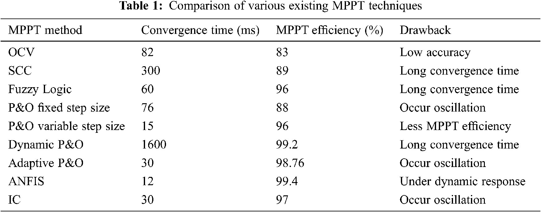
In this context, a new hybrid control method that combines both P&O and ANFIS is presented. It could never be easy to ignore the simplicity of implementation in P&O and accuracy, rapid recovery in ANFIS. Moreover, for small scale PV system environmental sensors has to be avoided for making it less expensive. In the proposed method, only one current sensor is sufficient, voltage can be measured by potential divider method. Hence a study of comparison is carried out in this work for P&O and proposed control strategy. The proposed method is having the benefits of both P&O and ANFIS respectively to get better results on rapid change over conditions. The performance comparison of various MPPT algorithm of existing methods is given in Tab. 1.
The main purpose of modelling an electrical circuit is to follow the circuit’s electrical behaviour so that it may be used with tools like MATLAB/Simulink. A PV unit has two types of resistance: series resistance (Rs) and parallel resistance (Rsh).
The term ‘Rs’ refers to the occurrence of current path losses caused by metals and contacts in the grid and the bus for current collection. The term ‘Rsh’ refers to an un-ideal p-n junction, which causes a parallel resistive-path leakage within the device. Fig. 1 depicts the equivalent circuit model of a PV module, which consists of a diode, an ideal current source, and series and parallel resistance.
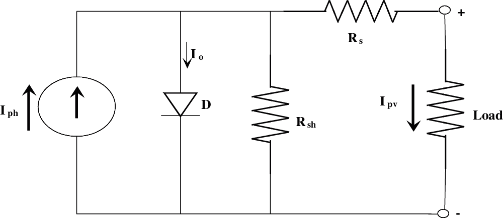
Figure 1: Equivalent circuit of a PV module
The PV Module is mathematically modeled from Eqs. (1) and (2),
Module photo-current:
The PV module output current is,
where,
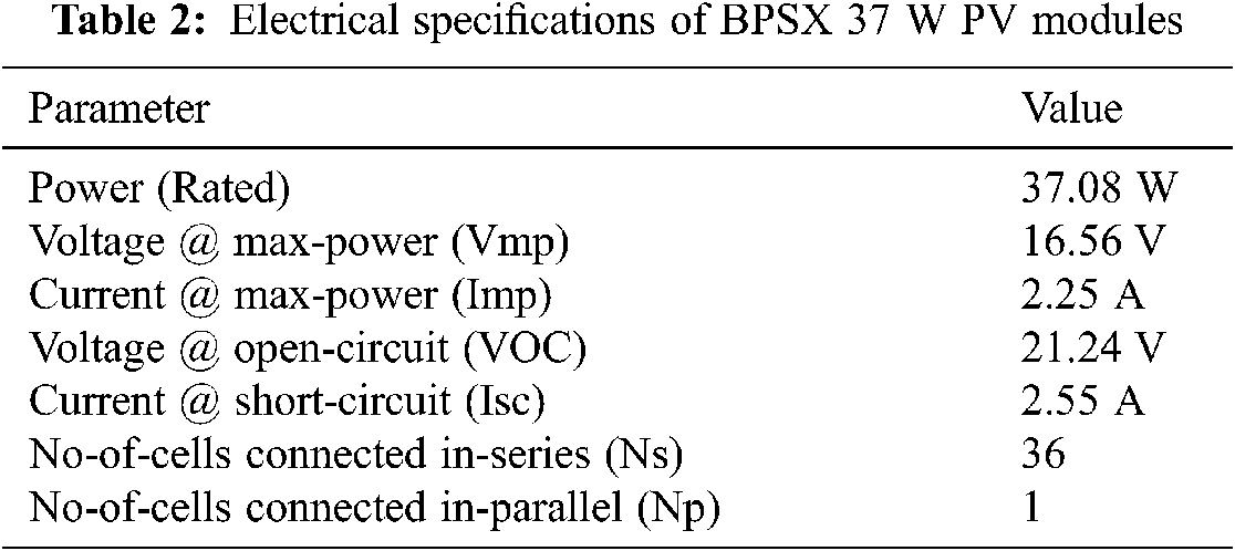
Vpv is the open circuit voltage, Np is taken as 1 and Ns is 36 for this module.
37 W Solkar made PV module-model is taken as module-model of reference for MATLAB/Simulink simulation and the panel ratings are given in Tab. 2.
The PV modules are persistently utilized with DC-DC converters to acquire the supreme power point. The MPPT associating the PV module to the load is appeared in Fig. 2. The MPPT comprises of DC-DC converter, a controller and load. The PV module’s output is associated with the converter and the converter’s output is associated with a resistive Load. DC-DC step-up/boost converters are frequently applied in SPV power systems to step-up the voltage from module side to load side. Hence, this converter is employed for the design of MPPT controller. The PV module’s output is connected to the converter and the converter’s output is connected to an R-Load.
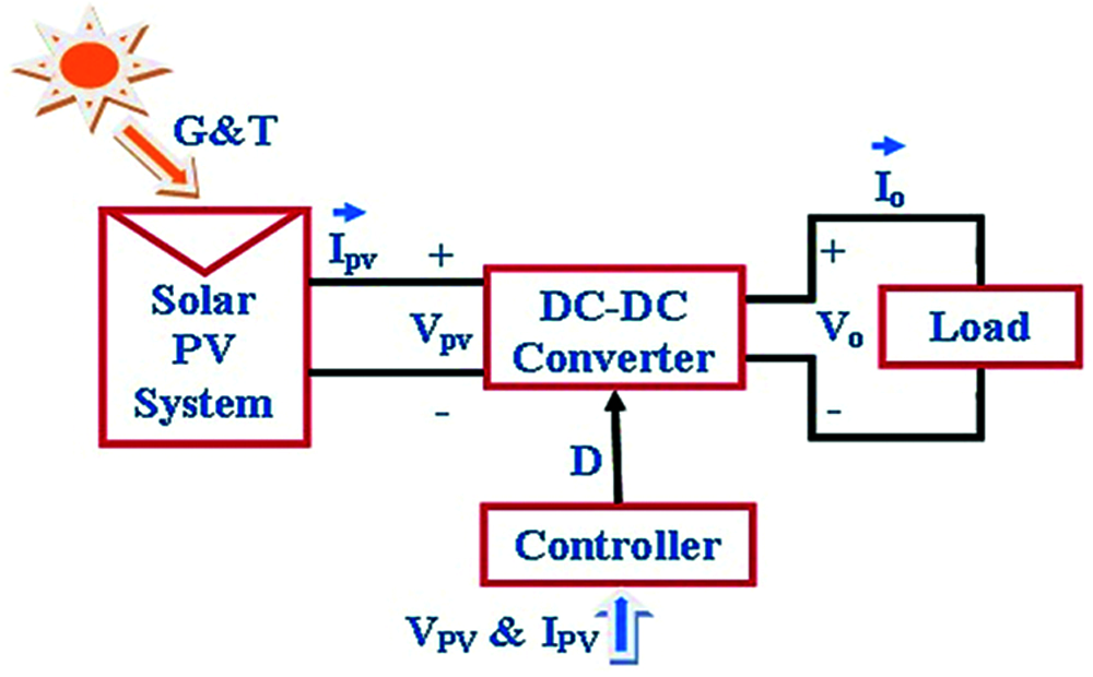
Figure 2: System configuration
The duty ratio (D) provided by the controller needs to track the highest power at that instant. The controller switches the boost converter switch ON and OFF to carry out the Pmax from the PV. A MOSFET is taken as a power electronic switch here. When the MOSFET is switched ON (mode1) the current through the inductor increases in a linear manner, so the diode is in the OFF state. However, when the switch is in off condition (mode2) the energy stored in the inductor is allowed to pass through the diode to the load. The pulsating DC current created by the switching process is smoothened by the capacitive filter and comparatively a pure dc voltage is given to the load.
2.3 Design of Boost/Step-Up Converter
Fig. 3 consists of an input DC voltage source (Vs), boost inductor (L), switch of control (S), diode (D), capacitor filter (C), and resistive load (R).
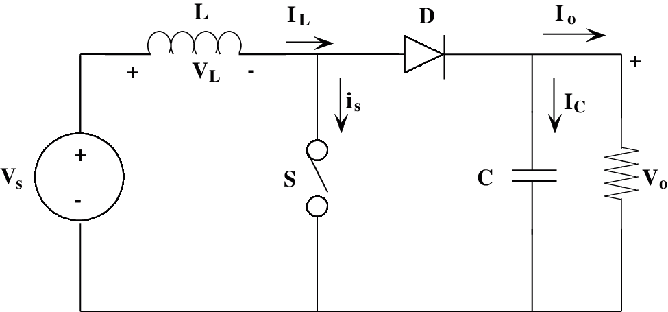
Figure 3: Configuration of DC-DC step-up converter
DC voltage gain (Mv) of this step-up converter is in Eq. (3),
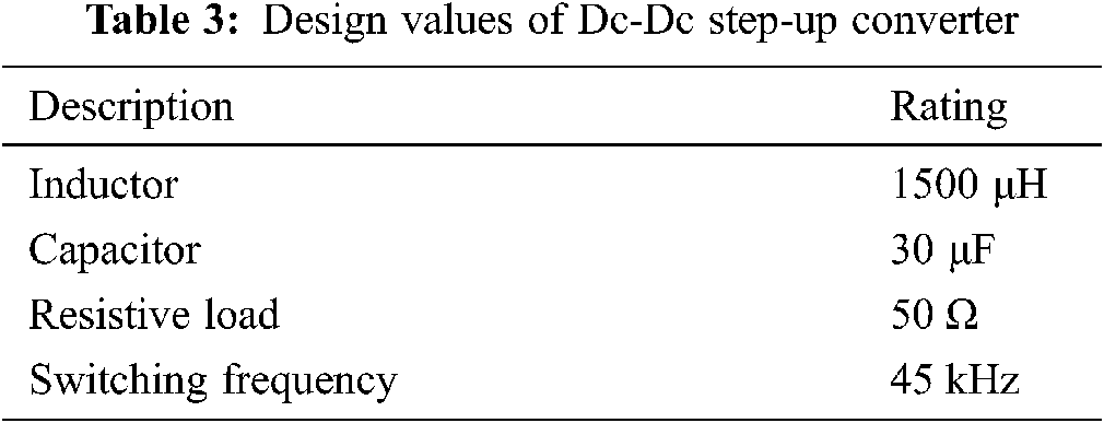
where, Vs is input voltage, Vo is output voltage and D is the duty ratio of the PWM signal. The electronic components designed values that are engaged in this simulation work is tabulated in Tab. 3.
The step-up converter operates in the incessant conduction form and inductance ‘L’ value is to be greater than Lb,
where, Lb is the smallest value to be in continuous transfer mode [25,26]. The lowest value of capacitor filter that will provide the output DC load current, when the diode D [27] is off is given by Cmin. The lowest value of the filter capacitance is given by
To receive maximum power, the MPPT has to give proper load for any external climatic conditions. DC-DC converters must be employed to modify the impedance of a source circuit [28–31] to the load circuit.
3.1 Perturbations and Obervation
The impedance matching of source to load can be done by MPPT, which changes the duty cycle of the converter thereby resulting in maximum power transfer to load. The V-I curve varies with external conditions such as irradiation and temperature. As a result, it is not possible to fix the duty cycle for the aforementioned conditions. The MPPT Algorithm [32] is in charge of keeping the operating point at its maximum under those conditions.
Fig. 4 depicts the flow chart of the P&O control method. Because of its simplicity, this method is widely used. This method allows for a small disturbance in the duty cycle as the power increases and decreases. The current and voltage has been taken as the two input parameters the power is been calculated at that occasion and compared with previous instant accordingly.
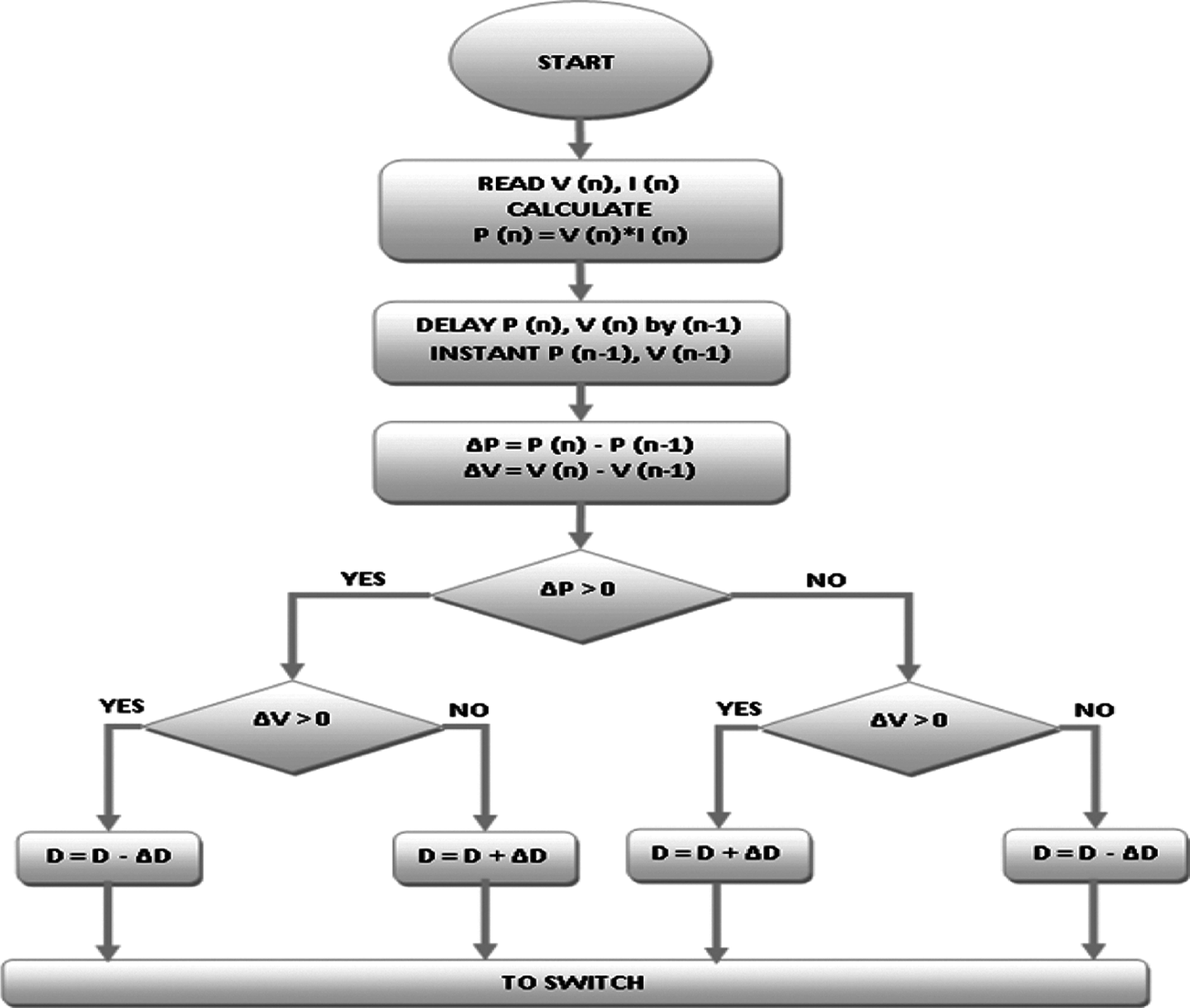
Figure 4: Flowchart of P&O MPPT controller
The instant power is calculated using Eqs. (6) and (7):
where,
P(ņ) & P(ņ−1) are the PV power at instants ņ and (ņ−1)
V(ņ) & V(ņ−1) are the PV voltage at instants ņ and (ņ−1)
I(ņ) & I(ņ−1) are the PV current at instants ņ and (ņ−1)
The voltage and current measured at equal interval of time period and the power is manipulated along with each instants. The change of power ‘delta P’ is deliberated from the difference of present and previous instant powers. Similarly the change of voltage ‘delta V’ is calculated from the difference of present and previous instant voltages. The rules of control action are shown in Tab. 4.

A Conventional P&O has the merit of easy implementation, but at sudden change in environmental conditions, the P&O fails to recover immediate response. ANFIS has the capability of fast recovery. This property is incorporated with P&O and is proposed here. The Proposed control scheme is depicted in Fig. 5 and the ANFIS block diagram is shown in Fig. 6 which are the parameters in MPPT controlling circuit and controlling algorithm and the ANFIS sample data pairs are tabulated in Tab. 5. The below four steps elaborates the working principle of the proposed scheme.
Step-1: In the proposed controller electrical parameters of PV side, current and voltage are taken as inputs. The values of voltage (V), current (I) for the instants n, (n−1) are measured from the results power (p) at instants n, (n−1) calculated.
Step-2: Instant power change ‘ΔP’ is checked if it is greater than the minimum set value ‘μP’. This μP value is set by the user according to their system requirements. In this case, a minimum change of Irradiation (say 50 W/m2) is set to be ANFIS alert.
Step-3: Whenever the system reaches positive or negative set value that is modulus value greater than ‘μP’ changes, the controller switches ANFIS to carry out the work for producing ‘ΔD’. This ‘ΔD’ is added with previous ‘D’ whether it is positive or negative is not considered here and this helps with fast recovery.
Step-4: In case of constant or gradual variation in insolationss, that is less than set value ‘μP’ this controller employs conventional P&O operation and is discussed earlier.
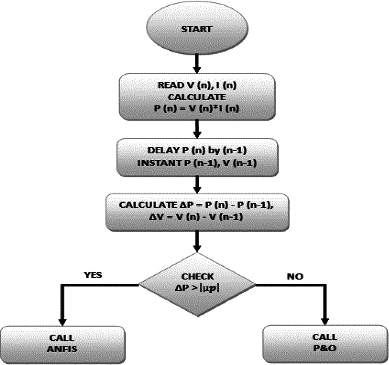
Figure 5: Proposed control scheme
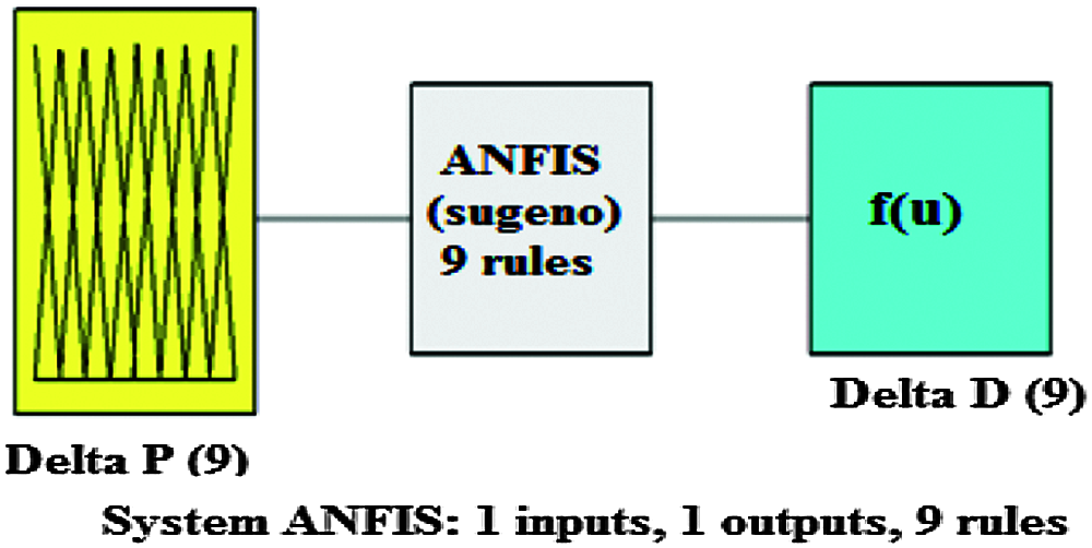
Figure 6: ANFIS block diagram

In different weather conditions (G and T), the maximum power (Pmax) values are obtained by proper modeling of the PV circuits. With proper load matching technique, these Pmax values are engaged to calculate the duty cycle (D) accordingly. After this process ‘ΔP’ and ‘ΔD’ pairs of around 2304 are utilized for training process and 289 pairs are engaged for checking process all parameters are derived from the necessary circuit behaviors. From that almost 13% of data pairs were engaged for checking process.
The sample data pairs of ‘ΔP’ and ‘ΔD’ for training process is tabulated in Tab. 4. From this data pairs, ANFIS is trained and FIS is created. This is a Sugeno type model and is having one input as ‘Delta P’ and one output as ‘Delta D’. In addition, nine rule bases and nine input membership functions are there. And also the number of rules depend on the number membership functions used in the proposed method.
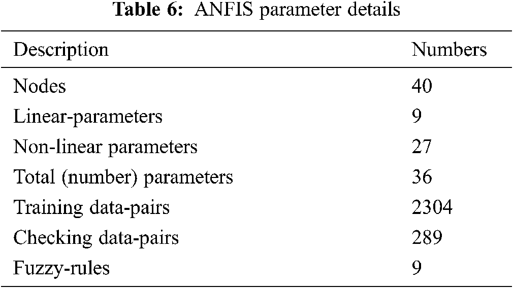
The training error when the data pairs are trained is depicted in Fig. 7. The error value of 0.0517 after 1000 epochs is reached. The training data and trained FIS output is plotted in Fig. 8. The required basic information of ANFIS system is tabulated in Tab. 6. The Input, “Delta P” is plotted against degree of membership function and is depicted in Fig. 9a.
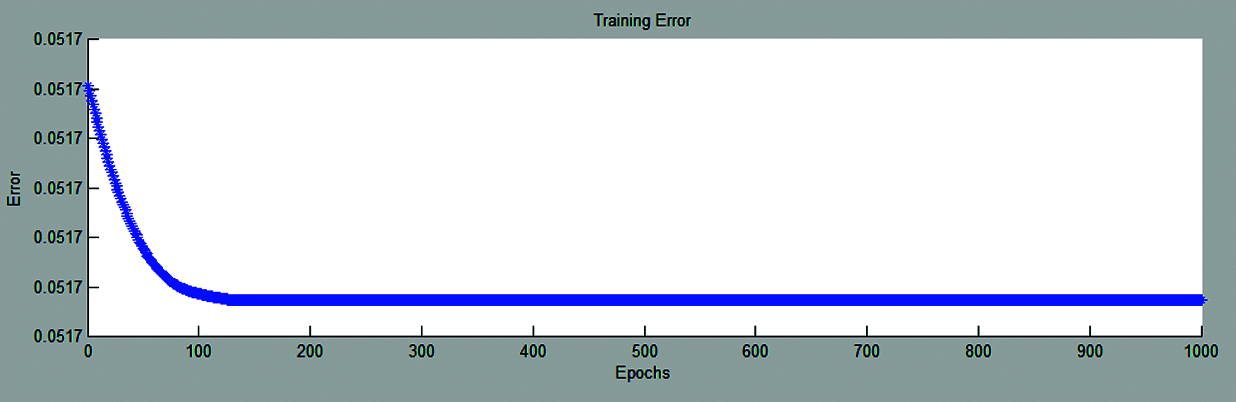
Figure 7: ANFIS training error
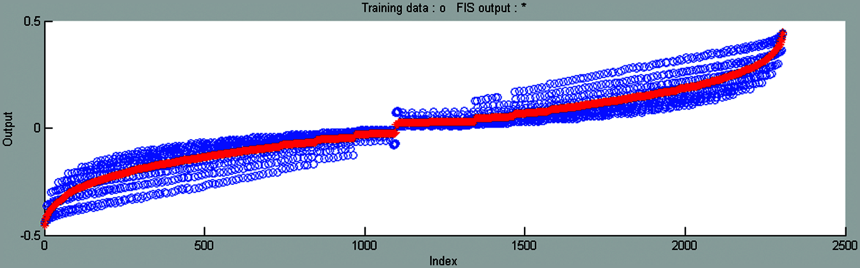
Figure 8: ANFIS training data and FIS output
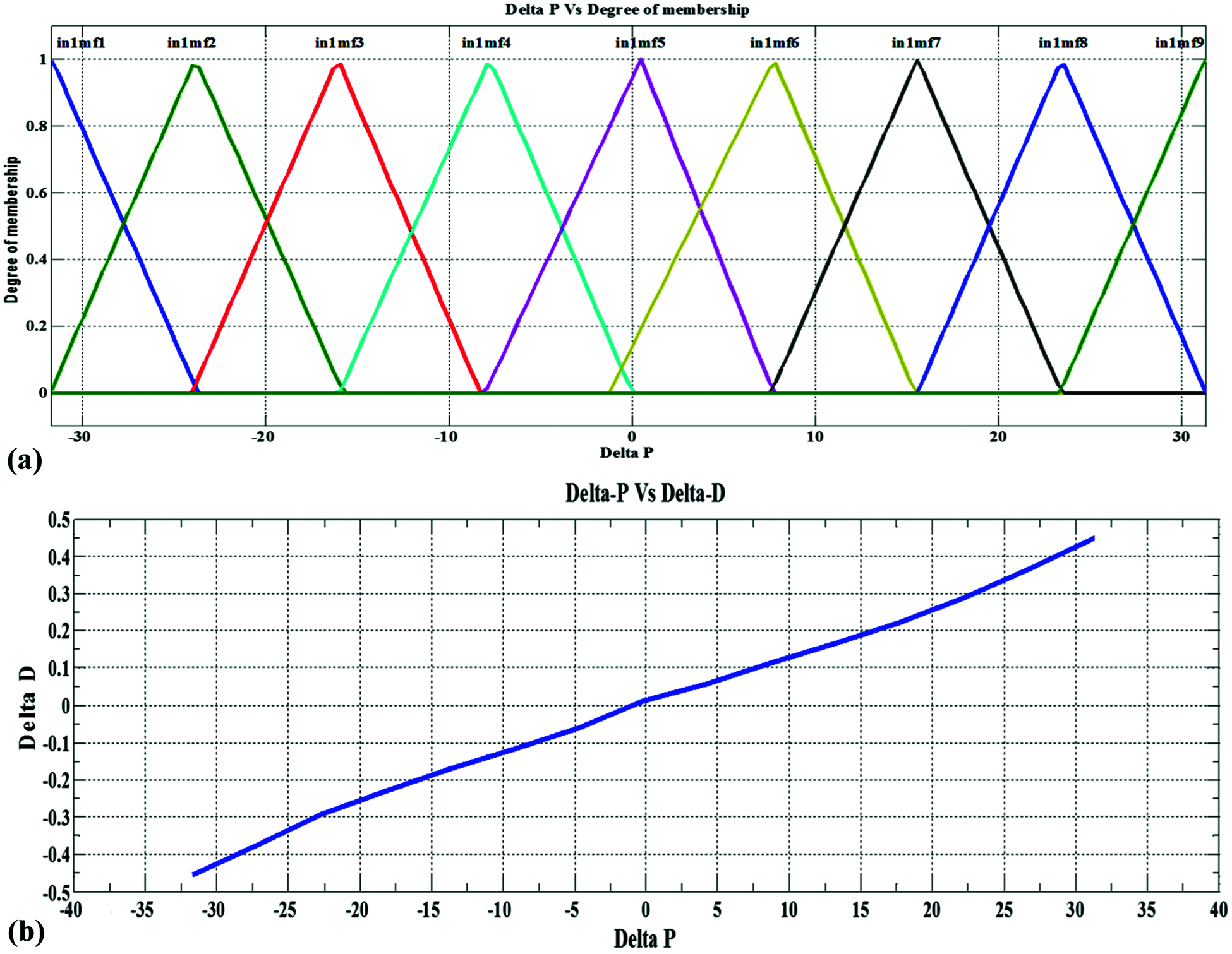
Figure 9: (a) ANFIS input membership function (Delta P) and (b) ANFIS surf-view
There are nine triangular membership functions employed here. It contain only straight lines for simplicity and the triangle represent the degree numbers while other membership function like trapezoidal represent in intervals. So the performance of triangular membership function is simple and more efficient than other membership function. The Degree is maintained from 0 to 1. The x-axis is “Delta P” that varies from +32 w to −32 w. ANFIS two-dimension surf-view against ‘ΔP’ and ‘ΔD’ are plotted in Fig. 9b. Whenever delta P increases delta D increases similarly whenever delta-P decreases delta D decreases.
4 Simulation Results and Discussions
Solkar made 37 w PV module electrical parameters are used to simulate the PV model. The voltage against current curves (I-V plot) and voltage against module generated power curves (P-V plot) for different irradiation at 25°C are simulated and is shown in Figs. 10a and 10b. Practically, In Indian environmental conditions, there will not be high dynamic change in temperature (T) but there will be dynamic change in irradiations. Hence to emulate this condition a pattern of insolation (G) having gradual increase considered for test condition and temperature is kept as 35°C in this case, that is day-to-day value. The proposed ANFIS adopted P&O based hybrid-controller and P&O controller both are employed for the above said patterns and the Duty Cycle variations are plotted in Fig. 12a. Whenever positive or negative sign dynamic change arises, hybrid-controller employs ANFIS otherwise P&O is called. Due to the increase in change of power and the reach of set value, the hybrid controller senses the change and operates accordingly.
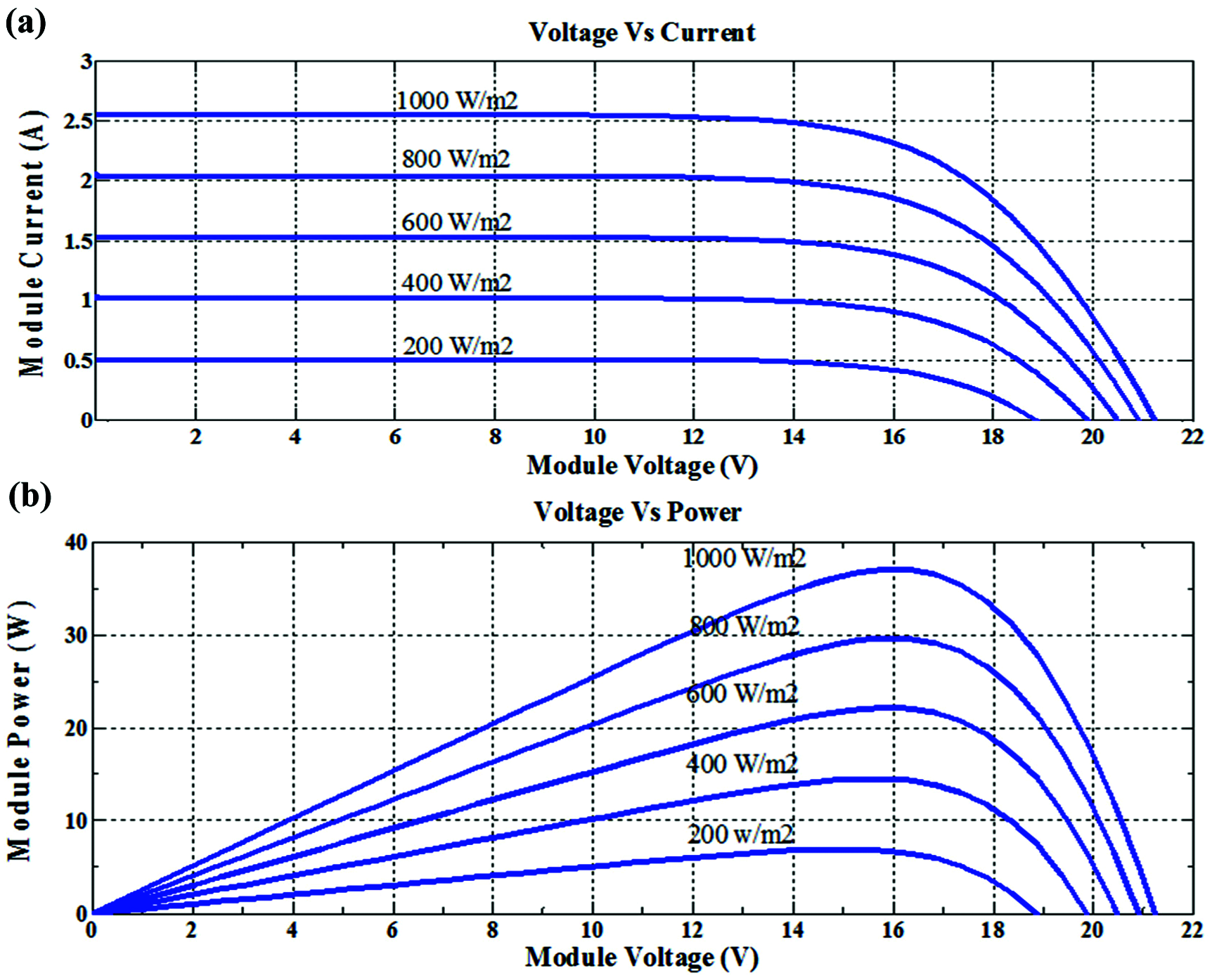
Figure 10: (a) V-I curve of PV module with different irradiation at 25°C (b) V-P curve of PV module with different irradiation at 25°C
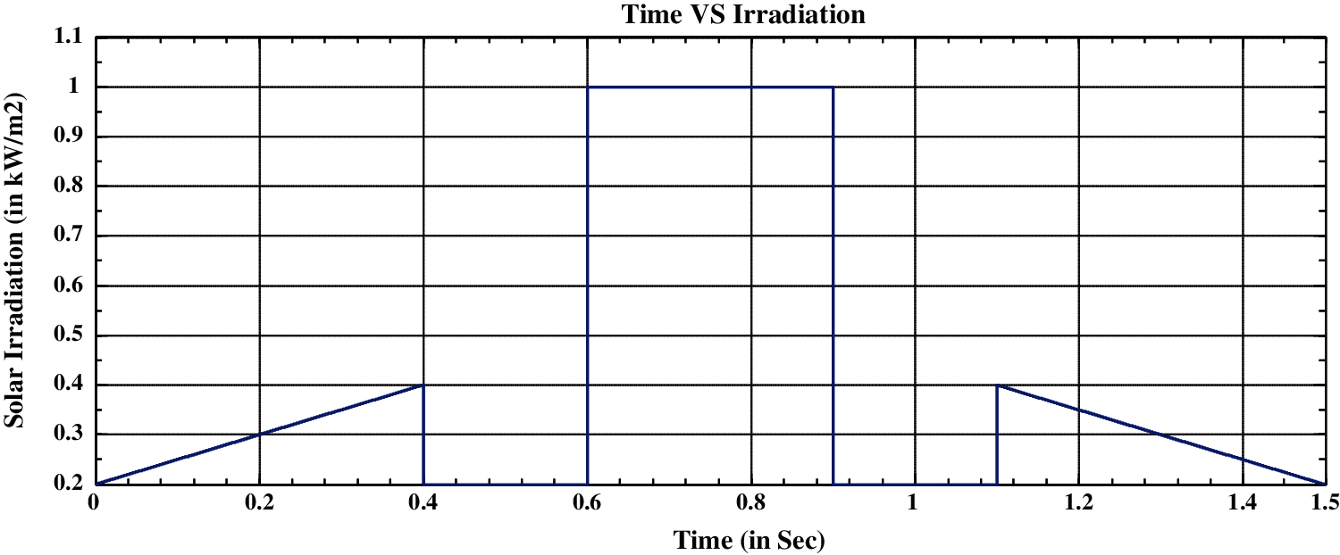
Figure 11: Solar irradiations with different patterns
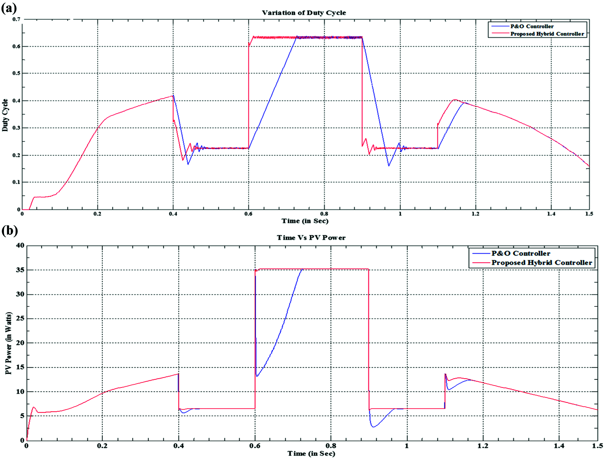
Figure 12: (a) Duty cycle variations corresponding to the input patterns (b) PV power variations corresponding to the input patterns
Solar irradiation with different nature of pattern is plotted in Fig. 11. In the time period of (0, 0.4, 0.4, 0.6, 0.6, 0.9, 0.9, 1.1, 1.5) S irradiation change of (200, 400, 200, 200, 1000, 1000, 200, 200, 400, 200) W/m2 is applied and this pattern comprises of a gradual positive increase in G of 0.2 to 0.4 kW/m2 and a gradual negative decrease in G of 1.1 to 1.5 S is allowed, then a dynamic change in G from 0.4 to 0.2 kW/m2 at 0.4 S and 1 to 0.2 kW/m2 at 0.9 S in negative side, 0.2 to 1 kW/m2 at 0.6 S and 0.2 to 0.4 kW/m2 at 1.1 S. Similarly to emulate static behavior of G from 0.4 to 0.6 S, 0.6 to 0.9 S and 0.9 to 1.1 S time period the G of 0.2, 1 and 0.2 kW/m2 is kept as constant.
4.1 Case (a): Dynamic Conditions in Irradiation
It is very apparent, in dynamic climatic change conditions at time periods (0.4, 0.6 and 0.9 S) without hybrid controller the P&O suffers to track rapid or fast changing conditions, it takes a great extent of time and is revealed in PV-voltage as shown in Fig. 13a and PV-current is shown in Fig. 13b variations and thus reflected in PV-power as shown in Fig. 12b and duty cycle too.
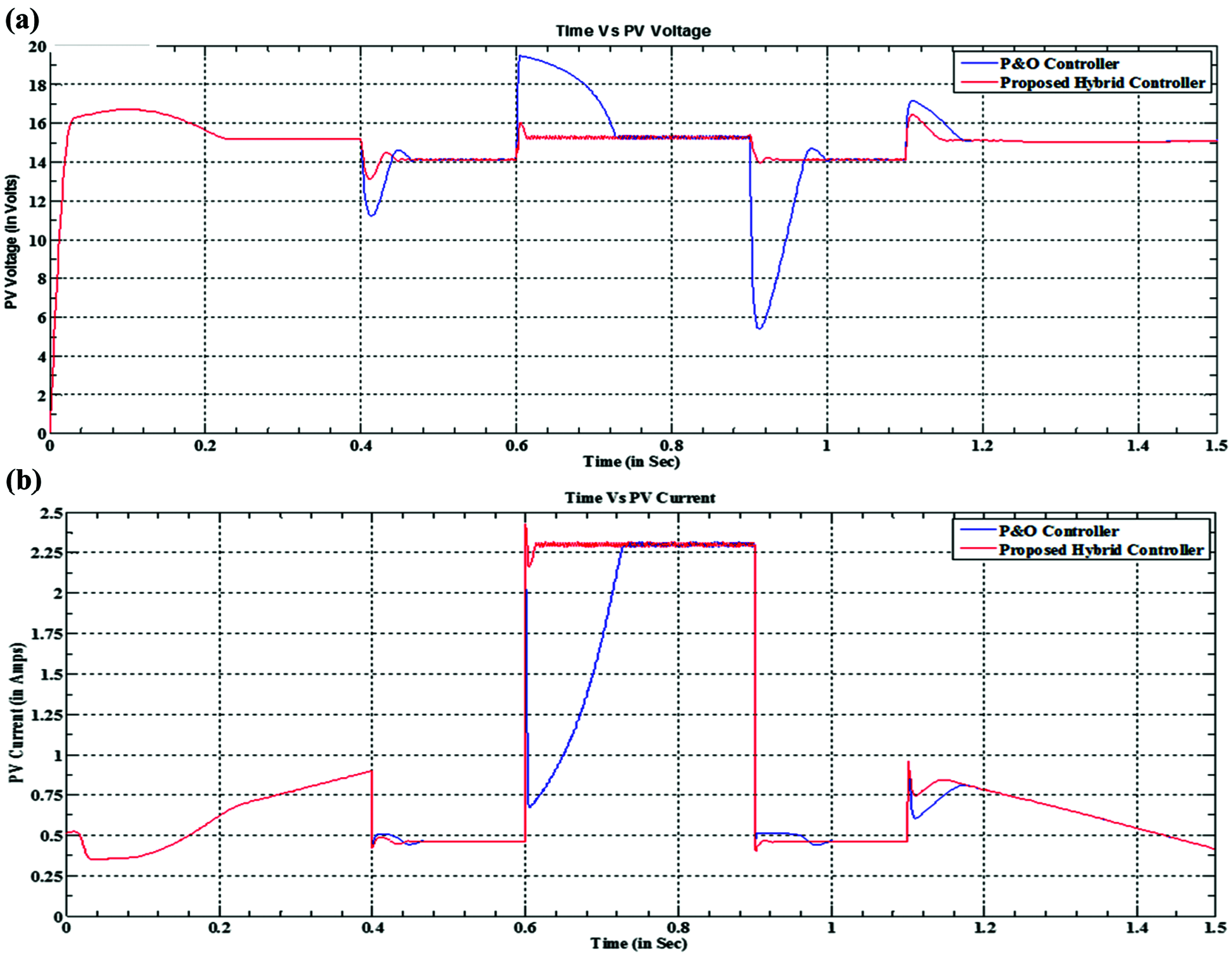
Figure 13: (a) PV voltage variations corresponding to the input patterns (b) PV current variations corresponding to the input patterns
Whereas, when the system make use of proposed ANFIS adopted P&O hybrid-controller in dynamic change, fast recovery is achieved. This is unambiguous from the plots of duty-ratio, PV-power, PV-voltage, PV-current curves. Comparatively, P&O takes less time in small dynamic change (0.4, 1, 1 S) and more time in high dynamic change which is at 0.9 S. But both cases the hybrid controller recovers rapidly.
4.2 Case (b): Static Conditions in Irradiation
When the change in perturbation is kept low, the accuracy is more in the output quantities and so P&O is capable to track these conditions. In this case, during (0.4–0.6, 0.6–0.9 and 0.9–1.1) S static irradiation condition engaged. Conventional P&O with less perturbation tracks well and so is hybrid controller is shown in this study and is confirmed by electrical characteristics of all the necessary plots that are depicted above. At stating 0 S, due to the PV system behavior it takes some time but later it tracks perfectly.
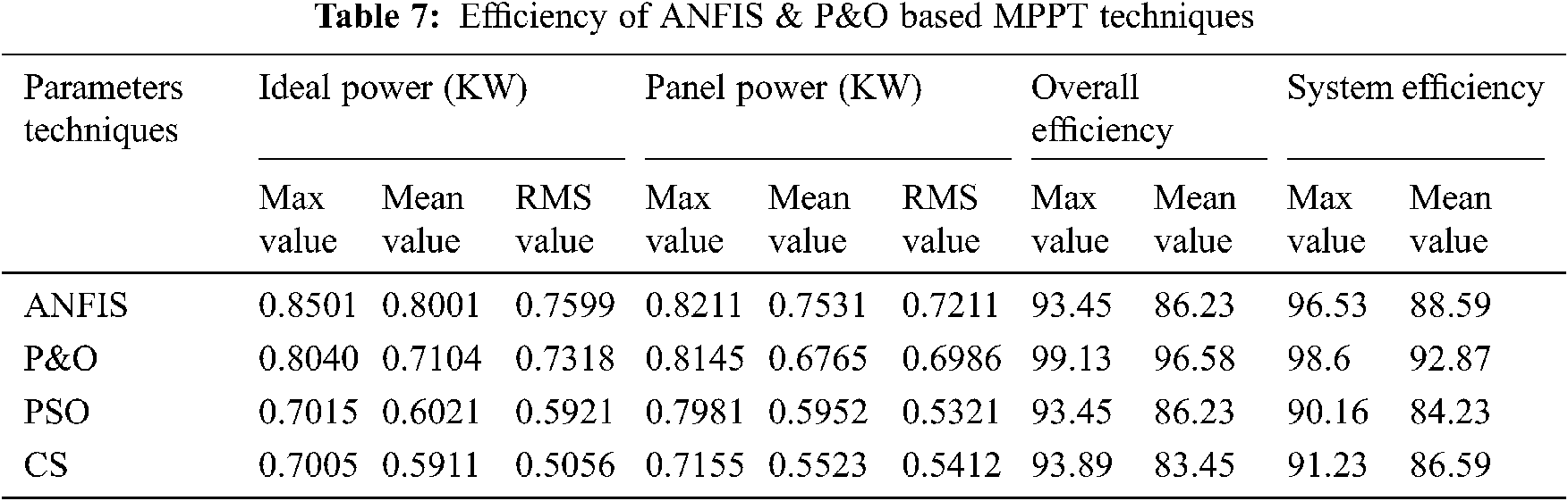
The tracking efficiency of the ANFIS and P&O based techniques can be found by the below formula and which is tabulated in Tab. 7,
5.1 Constant and Dynamic Weather Condition
The proposed ANFIS-based MPPT method has a tracking efficiency of 98.87%. On the other hand, the P&O MPPT method at step size 0.01 and 0.015 has a tracking efficiency of 97.34% and 92.71%. The tracking efficiency is higher in both cases.
The proposed method under dynamic weather conditions has a tracking efficiency of 98.34% and is higher than the tracking efficiency of the P&O MPPT at both step sizes, the P&O MPPT method at step size 0.01 and 0.015 has a tracking efficiency of 96.93% and 93.89%.
A novel hybrid-controller is proposed and examined for sudden change over or dynamic climatic conditions. The output of the PV system is displayed with MATLAB/SIMULINK software environment. The hasty recovery at quick varying conditions, in all the aspects like duty cycle, power, current and voltage are achieved by the proposed hybrid controller. Despite changing solar irradiance and temperature, the ANFIS-based MPPT method was able to monitor the new maximum power point. For two instances, it has a faster response and no oscillation around maximum power points as compared to P&O dependent MPPT. The findings were obtained using the ANFIS and P&O methods; the ANFIS method outperforms the P&O method in terms of efficiency and robustness. The ANFIS-based MPPT effectively extracts maximum available power from solar PV modules, enhances response time, and reduces oscillations around maximum power points, according to the findings. It is very difficult to get necessary data pairs ‘delta-P’ for training ANFIS for all necessary conditions. Practically it would take more data pairs, more time and is much more complex but in dynamic conditions it is achievable and thus works well with P&O. The P&O monitors the new MPP in 0.05 s with a tracking performance of 98.42 percent when solar irradiance changes abruptly (at 1 s). Due to the ease of implementation, P&O is unavoidable in other climatic conditions such as gradual and static and is executed in this study.
Acknowledgement: The author would like to thank Anna University and also we like to thank Anonymous reviewers for their so-called insights
Funding Statement: The authors received no specific funding for this study.
Conflicts of Interest: The authors declare that they have no conflicts of interest to report regarding the present study.
1. P. Soulatiantork, “Performance comparison of a two PV module experimental setup using a modified MPPT algorithm under real outdoor conditions,” Solar Energy, vol. 169, pp. 401–410, 2018. [Google Scholar]
2. J. P. Ram, T. S. Babu and N. Rajasekar, “A comprehensive review on solar PV maximum power point tracking techniques,” Renewable and Sustainable Energy Reviews, vol. 67, pp. 826–884, 2017. [Google Scholar]
3. H. Fathabadi, “Novel fast and high accuracy maximum power point tracking method for hybrid photovoltaic/fuel cell energy conversion systems,” Renewable and Sustainable Energy Reviews, vol. 106, pp. 232–242, 2017. [Google Scholar]
4. M. A. Eltawil and Z. Zhao, “MPPT techniques for photovoltaic applications,” Renewable and Sustainable Energy Reviews, vol. 25, pp. 703–813, 2013. [Google Scholar]
5. A. Jubaer and S. Zainal, “A modified P&O maximum power point tracking method with reduced steady state oscillation and improved tracking efficiency,” IEEE Transactions on Sustainable Energy, vol. 7, no. 4, pp. 1506–1515, 2016. [Google Scholar]
6. B. Faiza and L. Cherif, “Global maximum power point tracking based on ANFIS approach for PV array configurations under partial shading conditions,” Renewable and Sustainable Energy Reviews, vol. 77, pp. 875–889, 2017. [Google Scholar]
7. N. Salah, S. K. Mounia, L. Hocine, N. Ammar and D. C. Edgardo, “Enhanced auto-scaling incremental conductance MPPT method, implemented on low-cost microcontroller and SEPIC converter,” Solar Energy, vol. 180, pp. 152–168, 2019. [Google Scholar]
8. M. A. Danandeh, “Comparative and comprehensive review of maximum power point tracking methods for PV cells,” Renewable and Sustainable Energy Reviews, vol. 82, pp. 2743–2767, 2018. [Google Scholar]
9. M. Nabipour, M. Razaz, S. G. Seifossadat and S. Mortazavi, “A new MPPT scheme based on a novel fuzzy approach,” Renewable and Sustainable Energy Reviews, vol. 74, pp. 1147–1169, 2017. [Google Scholar]
10. M. A. Ramli, S. Twaha, K. Ishaque and Y. A. A. Turki, “A review on maximum power point tracking for photovoltaic systems with and without shading conditions,” Renewable and Sustainable Energy Reviews, vol. 67, pp. 144–159, 2017. [Google Scholar]
11. M. Seyedmahmoudian, B. Horan, T. K. Soon, R. Rahmani, A. M. T. Oo et al., “State of the art artificial intelligence-based MPPT techniques for mitigating partial shading effects on PV systems: A review,” Renewable and Sustainable Energy Reviews, vol. 64, pp. 435–455, 2016. [Google Scholar]
12. S. Messalti, A. Harrag and A. Loukriz, “A new variable step size neural networks MPPT controller: Review, simulation, and hardware implementation,” Renewable and Sustainable Energy Reviews, vol. 68, pp. 221–233, 2017. [Google Scholar]
13. E. Kandemir, N. S. Cetin and S. Borekci, “A comprehensive overview of maximum power extraction methods for PV systems,” Renewable and Sustainable Energy Reviews, vol. 78, pp. 93–112, 2017. [Google Scholar]
14. S. A. Rizzo and G. Scelba, “ANN based MPPT method for rapidly variable shading conditions,” Applied Energy, vol. 145, pp. 124–132, 2015. [Google Scholar]
15. P. Yadu, M. Mohiddin, P. K. Yadav and A. K. Sahu, “A modified MPPT technique for drift using neural networks,” in Proc. ICICCI, Greater Noida, India, pp. 23–29, 2017. [Google Scholar]
16. K. Punitha, D. Devaraj and S. Sakthivel, “Artificial neural network based modified incremental conductance algorithm for maximum power point tracking in photovoltaic system under partial shading conditions,” Energy, vol. 62, pp. 330–340, 2013. [Google Scholar]
17. Y. H. Liu, S. C. Wang and B. R. Peng, “Determining optimal membership functions of a FLC-based MPPT algorithm use the particle swarm optimization method,” in Proc. IIAI-AAI, Kumamoto, Japan, pp. 635–640, 2016. [Google Scholar]
18. A. Messai, A. Mellit, A. Guessoum and S. A. Kalogirou, “Maximum power point tracking using a GA optimized fuzzy logic controller and its FPGA implementation,” Solar Energy, vol. 85, pp. 265–277, 2011. [Google Scholar]
19. A. M. Noman, K. E. Addoweesh and A. I. Alolah, “Simulation and practical implementation of ANFIS-based MPPT method for PV applications using isolated Cuk converter,” International Journal of Photoenergy, vol. 2017, pp. 1–15, 2017. [Google Scholar]
20. F. Belhachat and C. Larbes, “Global maximum power point tracking based on ANFIS approach for PV array configurations under partial shading conditions,” Renewable and Sustainable Energy Reviews, vol. 77, pp. 875–889, 2017. [Google Scholar]
21. A. Abdolreza and R. I. Hamid, “A novel ANFIS-based MPPT controller for two-switch fly back inverter in photovoltaic systems,” Journal of Renewable and Sustainable Energy, vol. 1, no. 4, pp. 044702, 2019. [Google Scholar]
22. A. Mujahed, M. N. Ahmed, R. Hegazy and S. N. Kottakkaran, “Optimal parameter design of fractional order control based INC-MPPT for PV system,” Solar Energy, vol. 159, pp. 650–664, 2018. [Google Scholar]
23. N. Salah, S. K. Mounia, L. Hocine, N. Ammar and D. C. Edgardo, “Enhanced auto-scaling incremental conductance MPPT method, implemented on low-cost microcontroller and SEPIC converter,” Solar Energy, vol. 180, pp. 152–168, 2019. [Google Scholar]
24. M. Salimi, “Practical implementation of the lyapunov based nonlinear controller in DC-DC boost converter for MPPT of the PV systems,” Solar Energy, vol. 173, pp. 246–255, 2018. [Google Scholar]
25. A. Razman and W. T. Chee, “Design of boost converter based on maximum power point resistance for photovoltaic applications,” Solar Energy, vol. 160, pp. 322–335, 2018. [Google Scholar]
26. B. Abdelhakim, C. Ilhami and K. Kayisli, “Implementation of a modified P&O-MPPT algorithm adapted for varying solar radiation conditions,” Electrical Engineering, vol. 99, pp. 839–846, 2016. [Google Scholar]
27. Y. S. Joel, H. V. Saikumar and S. S. R. Patange, “Design & performance analysis of fuzzy based MPPT control using two-switch non inverting buck-boost converter,” in Proc. ICEPES, Bhopal, India, 2016. [Google Scholar]
28. B. Loubna, H. Mohammed, H. Bekkay and B. Hicham, “A new MPPT-based ANN for photovoltaic system under partial shading conditions,” Energy Prcedia, vol. 111, pp. 924–933, 2017. [Google Scholar]
29. R. Donny and S. Masahito, “ANFIS based a two-phase interleaved boost converter for photovoltaic system,” in Proc. INTECH, Luton, UK, pp. 19–24, 2014. [Google Scholar]
30. A. Ahilan and P. Deepa, “Design for reliablity: A novel counter matrix code for FPGA based quality applications,” in Proc. ASQED, Kula Lumpur, Malaysia, 2015. [Google Scholar]
31. R. Dhaya, R. Kanrthavel and A. Ahilan, “Developing an energy-efficient ubiquitous agriculture mobile sensor network-based threshold built-in MAC routing protocol (TBMP),” Soft Computing, vol. 1, pp. 1–11, 2021. [Google Scholar]
32. L. Shang, H. Guo and W. Zhu, “An improved MPPT control strategy based on incremental conductance algorithm,” Protection and Control of Modern Power System, vol. 3, no. 1, pp. 14–27, 2020. [Google Scholar]
 | This work is licensed under a Creative Commons Attribution 4.0 International License, which permits unrestricted use, distribution, and reproduction in any medium, provided the original work is properly cited. |