DOI:10.32604/iasc.2022.022067
| Intelligent Automation & Soft Computing DOI:10.32604/iasc.2022.022067 | |
| Article |
Vision-Aided Path Planning Using Low-Cost Gene Encoding for a Mobile Robot
Department of Power Mechanical Engineering, National Tsing Hua University, Hsinchu, 30013, Taiwan
*Corresponding Author: Rongshun Chen. Email: rchen@pme.nthu.edu.tw
Received: 26 July 2021; Accepted: 08 September 2021
Abstract: Path planning is intrinsically regarded as a multi-objective optimization problem (MOOP) that simultaneously optimizes the shortest path and the least collision-free distance to obstacles. This work develops a novel optimized approach using the genetic algorithm (GA) to drive the multi-objective evolutionary algorithm (MOEA) for the path planning of a mobile robot in a given finite environment. To represent the positions of a mobile robot as integer-type genes in a chromosome of the GA, a grid-based method is also introduced to relax the complex environment to a simple grid-based map. The system architecture is composed of a mobile robot, embedded with the robot operating system (ROS), the ArUco system and a laptop, executing the algorithms of path planning and image processing. Both simulations and experimental results are presented to verify the feasibility of the proposed method. In applications, this work can be employed in a commercial ball-collecting or an object-carrying robot.
Keywords: Path planning; genetic algorithm; multi-objective evolutionary algorithm; vision localization
Over the past years, due to the advancement in the technologies of mechanics and electronics, mobile robots have been developed to cope with many challenging and hazardous tasks in a tough environment that is usually not considered a properly reachable workplace for humans. For instance, there are extremely dangerous situations around the world, where bombs require to be defused to rescue people on site by soldiers or experts, whose lives are also threatened owing to a number of unpredictable factors. For this reason, self-driven robots are very suitable to perform the extremely risky task, bomb removal, to keep the safety of soldiers or experts. Moreover, several autonomous robots have been delivered by NASA to explore the related signs to prove the existence of water or creatures on Mars, which is too far from Earth and too dangerous to be landed and prospected by astronauts.
In addition, the year of 2020 was deemed a particularly difficult period for the governments and people all over the globe to combat the pandemic of COVID-19, which has triggered unprecedented influence on the global economy and life menaces to humans. The authorities of many countries around the world have issued the policies of a social distance which people maintain against infection and even of lockdown for people in the out-of-control areas to protect from the outbreak of coronavirus. Though under such a tough circumstance, people still have to be permitted to work or get supplies in a number of essential businesses, such as supermarkets, delivery services, medical care, etc. Hence, it is one of the most significant topics starting from 2020 for the way to minimize the risk of infection of the coronavirus between people that are exposed to public fields, in order to sustain essential economic activities.
With this regard, several researches have been mainly dedicated to making it independent for mobile robots to move from one point to another in an optimal manner [1], i.e., barely with the interference of additional human operators. An extensive survey is conducted on several techniques for solving motion planning problems that satisfy certain optimization criteria and are subject to necessary constraints [2,3]. The contribution of mobile robots can be also extended to a wide range of fields such as the delivery, warehouse, nursing, etc. However, no matter where mobile robots are applied, several topics occur in the respects of mobile robots operating independently: fulfilling communication and interactions between the robots, collision avoidance, and task allocation [4]. As the techniques of communication and task allocation in the IoT industries have been improved and prevailing on a large scale [5], there exist many mature ways for mobile robots to transmit and broadcast critical information with other robots in the surroundings. Therefore, this research is mainly involved in the collision-free path planning, to autonomously complete the assigned missions from one location to another without any collision with other objects in a given finite environment.
In the real world, the path planning (PP) problem can be generally regarded as the MOOP that simultaneously optimizes the shortest path and the least collision-free distance to obstacles. However, challenges would occur when the characteristics of objectives may conflict with each other, i.e., the optimal solution of an objective function competes against that of the other one. To handle this problem as well as to aim at the real-time applications, the following contributions are mainly put forth by this work.
• The mathematical modeling is provided to represent the multi-objective PP problem in a grid-based mapping environment.
• The novel algorithm, based on the GA-driven MOEA with the low-cost gene encoding, is proposed to plan a collision-free path for the multi-objective PP problem within a tractable time.
• The centralized system architecture with a custom-designed mobile robot and a computing console is presented for real-world experiments to test the feasibility of the proposed PP algorithm. In the experiment, the ArUco system for the visual localization is employed to obtain the positions of the obstacles, which the mobile robot should avoid by walking along a planned collision-free path.
The remaining sections of this research are enumerated as follows. Section 2 summarizes the previous literature related to this work. Section 3 deliberates the mathematical formulation of the multi-objective PP problem. Next, the proposed PP algorithm and obstacle localization are detailed in Section 4 and Section 5, respectively. Furthermore, Section 6 provides the simulations and experimental results. Finally, Section 7 concludes the paper and specifies the prospects of this work.
In robot path planning, most of the traditional approaches are commonly applied in a high computational manner; hence, many methods concentrated on heuristic or meta-heuristic approaches to reduce the computational complexity and then to rapidly obtain the approximate solutions close enough to the globally optimal solution.
The A* search, proposed firstly in [6], selected every next node in the graph search using a best-first heuristic to determine an optimal distance from a current node to a goal. Over several decades, a plenty of variants of A* have been also invented to search a route more efficiently, such as D* [7], Lifelong Planning A* (LPA*) [8], etc. However, the A* family merely takes into account the single-objective optimization, instead of optimizing multiple objectives concurrently. Hence, the problem with multiple conflicting objectives could not be solved using the A*-related approaches.
Instead of the aforementioned graph-based methods, various meta-heuristic solutions were also invented to plan a near-optimal path for a mobile to pursue its goal. For instance, an approximation reasoning mechanism was accomplished using a fuzzy-logic controller to prevent a mobile robot from colliding the stationary obstacles, which was tested on a mobile robot system in an indoor environment [9]. The GA iterates the solutions in the search space to retrieve the best-fitted chromosome representing for the optimal tour, when applied to solve the path planning for the traveling salesman problem (TSP) [10]. In addition, a bundle version with the fuzzy logic controller and the GA was also created to solve the path planning of a mobile robot [11].
Due to such multiplicity of solutions, the MOEA [12] is thus introduced to develop a feasible path planning algorithm. Two typical evolutionary algorithms, the GA and the particle swarm optimization (PSO), can be the candidates as the solvers in the MOEA. This work is essentially a discrete and constrained optimization problem, which would result in the case that the PSO underperforms the GA in solution quality [13,14]. Even though being able to map a discrete optimization problem to a continuous one [15,16], the reinforced PSO still requires excessive processing steps, and is subsequently not as straightforward as the GA that is natively designed for discrete optimization problems. Therefore, the GA-driven MOEA is utilized in this work to aim at the real-world applications on the path planning with the obstacle avoidance for mobile robots.
Several visual sensing techniques have been recently invented to detect objects in a given finite environment [17–19]. Because the proposed path planning algorithm must be aware of all positions of the obstacles in a terrain with several square meters, a global vision-based sensing method, called the ArUco marker [20–22], is utilized in this work. During the last few years, the ArUco marker has been popularly applied to detect and to recognize static or dynamic objects [23,24], because it can offer low hardware cost, accurate solution, and complete six-degree-of-freedom (6-DOF) information of an object in the indoor localization.
The environment is partitioned with K cells squarely on each side, i.e., K2 cells in total, to form a grid-based map, each cell of which indicates the position where the mobile robot is at any moment. To elaborate on this concept, an example with K = 10 is provided in Fig. 1, where there exist 10-by-10 cells. In the cells, the rectangles represent the obstacles, while the circle and the triangle represent the starting and ending positions of robot, respectively. Additionally, the numbering from 0 to 9 is used to label the rows and columns, which is identical to the longitudinal and latitudinal axes in the map of Fig. 1, respectively.
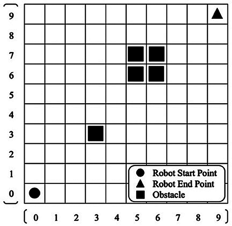
Figure 1: A exemplified map denoting the locations of the robot and obstacles
The mathematical modeling for the path planning in this work is inspired by the principle of integer linear programming, in which the cell position occupied by a robot or each obstacle on the map of Fig. 1 requires both longitudinal and latitudinal coordinates to be integers. Afterwards, the actual cells that are passed by the robot can be regarded as the control points, constituting a planned path for the robot to move from an initial position to a final target on the map.
For the purpose of encoding each gene with an integer in a chromosome of the GA, the cell position of the mobile robot in the map of Fig. 1 can be formulated as a one-dimensional number, which can be transferred from the original two-dimensional coordinates by Eq. (1).
where the cell position of the robot is numbered by m, which can be related to the coordinates (ri, ci). The variables ri and ci are row and column numbers, respectively. N is the amount of control points. If (ri, ci) is set to (2, 7) as an example, m will be derived to the value 27.
The safe margin is a desired distance between the robot and the obstacle to guarantee that collisions will not occur [25]. In Fig. 2 each cell is numbered by Eq. (1). Fig. 2a illustrates an obstacle cell m, in green color, surrounded by eight orange cells, forming the safe margin. For the multiple obstacles in a group, all of the safe margins for the square and irregular obstacles can be retrieved, as described in Figs. 2b and 2c, respectively.

Figure 2: Demonstration of safe margins for different situations (green cells: Obstacles; orange cells: safe locations of robots. (a) for a single cell (b) for square cells (c) for irregular cells
In the path planning of the mobile robot, two objectives, the shortest traveling tour to the target and the least overall safe margin to obstacles, are required to be achieved at the same time. Therefore, the mathematical models are represented as follows:
Minimize traveling tour to the target:
Minimize overall safe margin to obstacles:
Subject to:
where ri and ci, composing the position P of the mobile robot, represent the row and column numbers, respectively on the map in Fig. 1, on which S and E are the starting and ending points of the robot, respectively. Moreover, every position of the obstacle B, is static and invariant at all time. The functions f1 and f2 calculate the traveling tour of the robot to the target and the summation of the safe margins from the robot to the centroids of all obstacles, respectively. N and M stand for the numbers of control points and obstacles, respectively.
In this work, a candidate solution (chromosome) of the GA comprises a string of genes that are the steps for the robot to move from a starting point to an ending one. As the number of genes grows up, the mobile robot can obtain a smoother path, while it will suffer much more computational time. To reduce the gradually increasing computational time, a chromosome here is not encoded as K2 cells for a K-by-K map, but only K cells, to represent a candidate solution in the GA, which is thereby coined the low-cost gene encoding in this work.
Fig. 3 elaborates on the problem-solving flow of the proposed method. To begin with, the initial population is randomly generated by iteratively adding the aforementioned chromosome with low-cost genes. After applying Eq. (2) to evaluate the functions of two interested objectives, traveling tour to the target and overall safe margin to obstacles, the initial Pareto fronts will be retrieved for checking the dominance of one solution in comparison with another solution in the initial population. Because the stop criterion here is a certain number of generations, the flow will proceed to the next step that calculates the sum of the fitness and penalty functions for all candidate solutions. Then, a sequence of steps, such as the parent selection with the rank-based technique, the crossover, the mutation, and the survivor selection, will be repeated many generations to generate a new population, which will compete with the current population to obtain a better Pareto front. Until the number of terminating generations is reached, the solutions on the best Pareto front will be the best chromosomes.
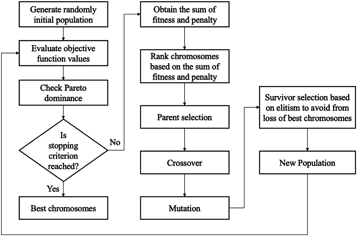
Figure 3: The problem-solving flow of the GA-driven MOEA with low-cost gene encoding
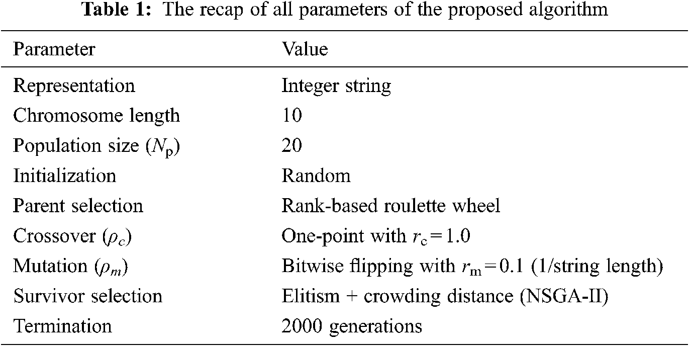
Prior to solve the path planning by the GA-driven MOEA, some parameters should be initially defined, such as the population size (Np), the maximal number of generations (Nt), the crossover rate (ρc), the mutation rate (ρm) and so on. The recap of all parameters of the proposed algorithm is listed as Tab. 1.
Next, all of the evolutionary operators utilized in this work will be addressed in detail from Sections 4.1 to 4.5.
4.1 Representation of a Solution
To represent a solution by a chromosome, a grid-based map with K = 10 is exemplified in Fig. 4, where the left-hand and right-hand sides display the phenotype and genotype of a candidate solution tour of the mobile robot, respectively. The phenotype of a solution tour means that the tour is moved along by the mobile robot; the genotype of a solution tour indicates that the cell positions of the tour are encoded as integer-type genes in a chromosome.
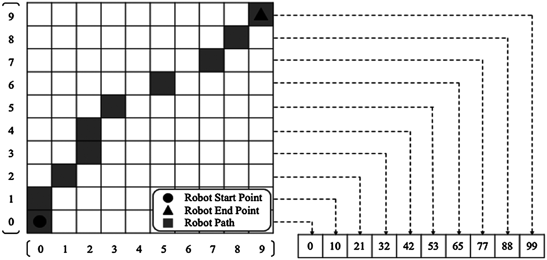
Figure 4: An example of the candicate solution tour for the mobile robot (the left and the right represent the phenotype and the genotype of the solution tour, respectively.)
There are several ways to select parent chromosomes for a mating pool, which provides the candidate parents prior to the stage of crossover operation. Despite being one of the most popular selection tactics, the proportional selection has some drawbacks. For instance, chromosomes with higher fitness will be preferred at almost every selection, and will finally dominate the population in a short time, which is known as the premature convergence that leads to no further evolution. To alleviate this side-effect, the rank-based selection [26], with the time complexity of O(Np log Np), is used as an alternative, because the selection probability of a chromosome is related to its rank in the population, instead of its fitness value. As a result, the selection probabilities of a highly-selected chromosome and any top-rank chromosome are identical in one population.
A well-known single-point crossover operator with the time complexity of O(ρc Np) is adopted in this work to handle the integer-encoded GA. It is the crossover rate ρc that decides whether the crossover operation is applied on the preset crossover point of two parent chromosomes or not. A higher crossover rate produces more new offspring, but many better current chromosomes will be lost. In contrast, a lower crossover rate is apt to bring the worse chromosomes to the next generation, conducting a more conservative exploration in the search space. Hence, it is suggested that a reasonable crossover rate should be chosen to prove the solution quality.
The mutation operator perturbs some genes in a chromosome to reintroduce the diversity of solutions onto the population, and then prevents the search from getting stuck at local optima. In the mutation operator, the mutation rate ρm is set as a small number to prove that the mutated chromosome will not vastly differ from its original one.
Given a gene Xn in a chromosome as the cell number where the robot arrives when it walks to row n in Fig. 4, if Xn needs to be mutated, an arbitrary value can be randomized and limited within the range of [10n, 10n + 9]. For instance, the genes X0 and X8 can only be mutated from 0 to 9 and from 80 to 89, respectively. The time complexity of the proposed mutation operator is O(ρm K Np). A more specific example is depicted in Fig. 5.
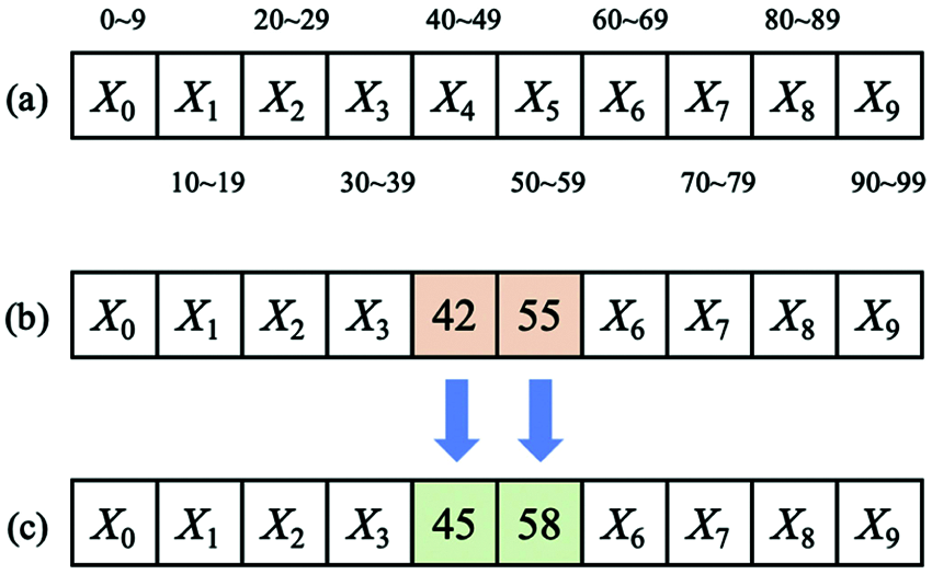
Figure 5: Demonstration for the mutation operator on certain genes
Fig. 5a illustrates the range of the integer number for each gene. In Fig. 5b, genes X4 and X5 are originally 42 and 55. After applying the mutation operator, X4 and X5 could be mutated to some value randomized from the integer sets of [40, 41, …, 49] and [50, 51, …, 58, 59], respectively; for instance, X4 and X5 might become 45 and 58 respectively, as shown in Fig. 5c.
The so-called survivor selection is implemented by copying a few parent chromosomes and introducing some offspring chromosomes to keep the population size as a preset number of Np in the new generation. Therefore, at this stage, the surviving chromosomes are selected and the disqualified ones are forsaken. For example, in each generation there exist Np and μ chromosomes, respectively in the parenthood and childhood. Eventually the total number of the chromosomes, Np + μ, has to be reduced to Np to maintain the constant population size. Although numerous methodologies can be applied for the survivor selection, aimed at a real-time application, this study employs a polynomial algorithm, called NSGA-II [27] with the time complexity of O(U Np2). U denotes the number of objectives. The primary concept of NSGA-II is elitism, which duplicates the best parent chromosomes, i.e., the elite chromosomes, to the population in the next generation. It can prevent the GA from losing the optimal solution and then drive the entire genetic search to the correct destination.
5 Obstacle Localization by the ArUco System
For a robot to run along a planned path, it needs to detect and to localize the obstacles in advance. This work utilizes a global visual sensing technique, which is able to detect obstacles behind an obstacle and the existence of blind spots, in comparison with a local visual sensing method. A type of fiducial marker, called the ArUco marker, is employed. The ArUco marker has much advantageous in the global localization of obstacles in an indoor environment. Firstly, multiple obstacles glued with ArUco markers can be detected simultaneously using only a single camera. Secondly, a localization error of the ArUco marker will be regardless of time, resulting from the fact that a cumulative error will not occur in the ArUco system. According to [28], the real-time positioning accuracy of fiducial markers can achieve the level of centimeter, or even sub-centimeter. Thirdly, a comparison of ArUco with AprilTag under noisy sensor data shows that ArUco has high robustness in a noisy environment [29]. Finally, given an extra reference dimension (marker size) of the fiducial marker, the position of the marker can be obtained, by simply applying the built-in classical image processing algorithms from OpenCV libraries, such as binarization, edge detection, feature extraction.
There are several steps for the image processing in the ArUco system. To begin with, all the contours of the images that are captured from the camera will be extracted and filtered to several four-corner polygons, which are consequently decoded to determine whether they are valid markers or not. Next, the four corners of a valid marker will be identified to obtain the homogeneous transformation matrix
where Rot represents the rotation matrix between the frames, and Tran represents the translation vector between the frames.
Finally, the ArUco system can compute the position of marker relative to the optical center of the camera, and offers the rotational Euler angles by using Eq. (3), provided that the marker size is known.
In this work, the ArUco markers are arranged as an array with 7 × 7 squares, each of which is either black or white, except for the outer two rows and columns that are kept the black squares, as an example presented in Fig. 6a. After successfully localizing the ArUco marker, via a camera and by libraries provided in [20,21], the coordinate frame of the marker will be determined, as illustrated in Fig. 6b, where axes x, y and z are in red, green, and blue lines, respectively.

Figure 6: The location of a raw marker can be analyzed via the ArUco system (a) raw marker (b) processed marker
6 Simulations and Experimental Results
6.1 Determination of Parameters
To verify the proposed path planning algorithm, the mobile robot is located on the environment of a map with 10 × 10 cells, as shown in Fig. 7, where the starting and ending points are labelled respectively as a circle and a triangle, and several obstacles are denoted as rectangles.
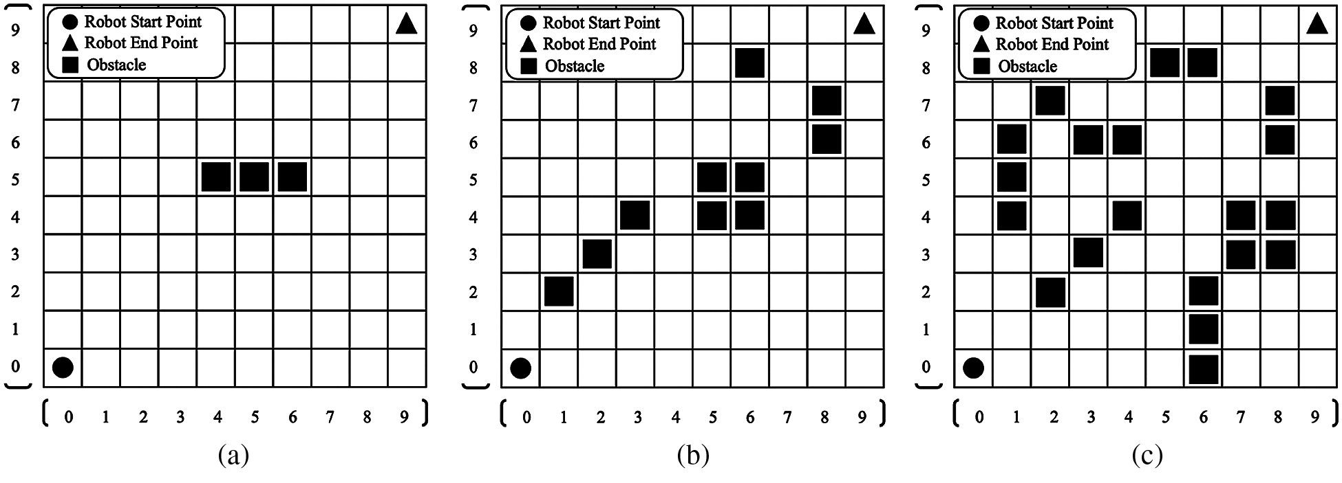
Figure 7: Three test scenarios for verification (a) elementary plan (EP) (b) median plan (MP) (c) advanced plan (AP)
The test scenarios with three-, ten-, and twenty-obstacles, named as elementary, medium and advanced plans, are provided respectively in Figs. 7a–7c. The preset ρc and ρm are 1.0 and 0.1, respectively, and the chromosome length and the population size Np are 10 and 20, respectively. The main loop terminates when a stop criterion or a maximum number of generations is satisfied.
The concept of the Pareto front, on which the solutions will not be dominated by each other, is used to establish a non-dominated solution set in the MOOP. The NSGA-II is utilized to optimize the Pareto front [27]. The results by simulating the objective spaces of the elementary, medium and advanced scenarios are shown in Figs. 8a–8c, respectively. In Fig. 8, the left-hand-side figures showing the initial generations are randomly distributed, and the right-hand-side figures displaying the Pareto fronts are inclined to the lower-left corner of the coordinates as the generations increase, and finally converge at the generation of 2,000.
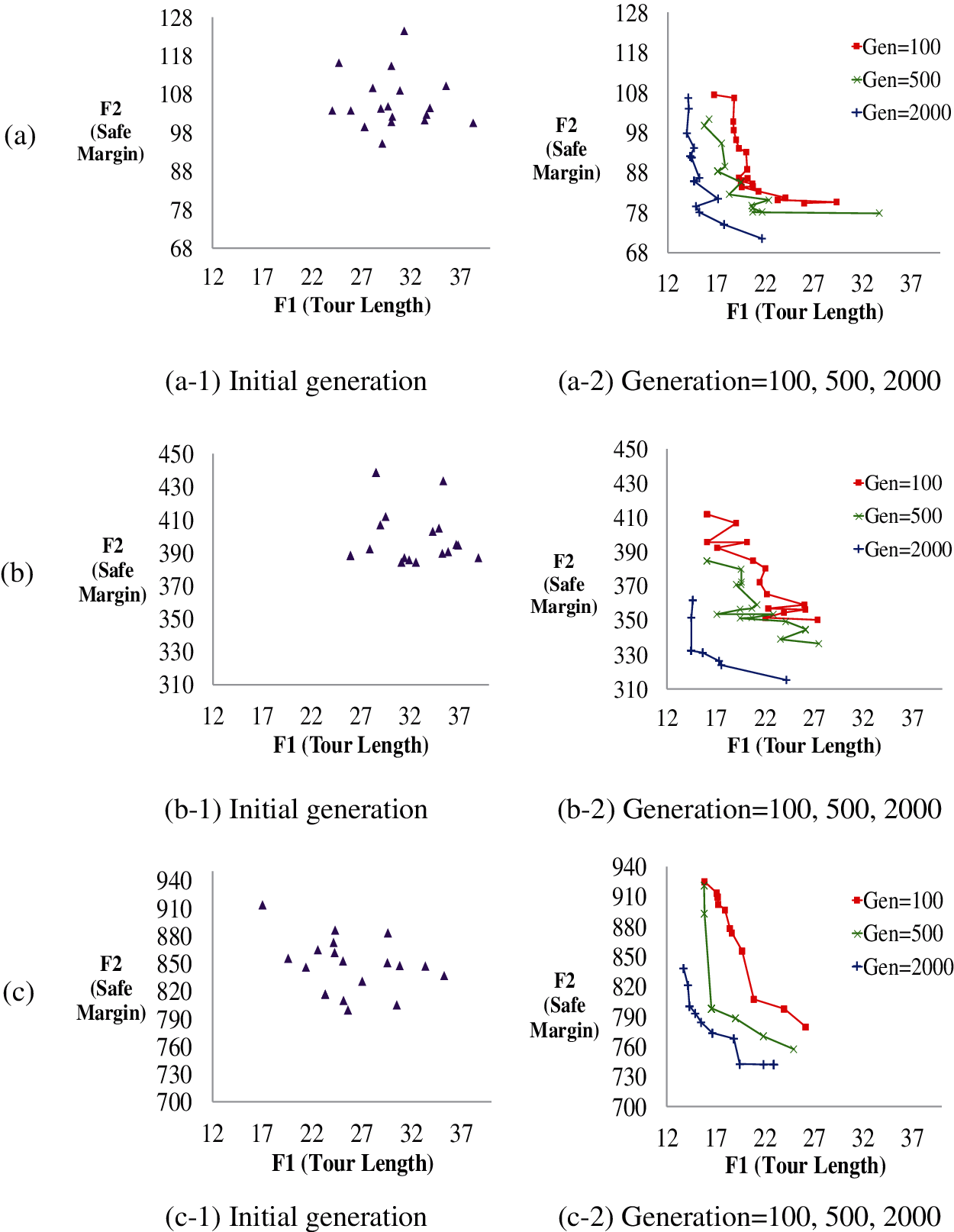
Figure 8: The objective spaces to observe the initial generation and the pareto fronts in different generations for three test scenarios (a) EP (b) MP (c) AP
The system architecture of the vision-aided collision-free pathfinder is depicted in Fig. 9. In the system, the ROS [30] and Python 3 are installed in a laptop (Console) running Ubuntu 18.04, and an embedded system using a STM32 microcontroller is mounted on a two-wheel mobile robot (Agent).
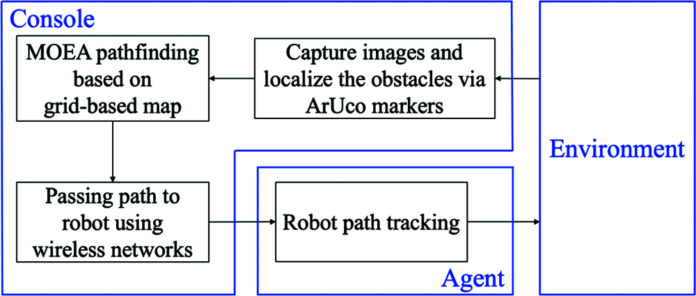
Figure 9: The block diagram of the vision-aided collision-free pathfinder
Firstly, the Console utilizes an aloft-located RGB camera to capture the entire view of the experimental environment and then to decrypt the ArUco markers via the algorithms, proposed in [20–22], for localization of the obstacles. Thereafter, the pre-planned path with the obstacle avoidance is derived using the proposed path planning based on the MOEA. Next, the Console emits the pre-planned path, carried by wireless signals, which is tracked by the Agent to its desired destination.
The hardware architecture is displayed in Fig. 10 for three main parts: an RGB camera fixed under the ceiling (Fig. 10a), a mobile robot equipped with an embedded system in the experimental environment with an area of 4 × 4 m2 (Fig. 10b), and several hand-made dummy boxes adhered with ArUco markers for representation of the obstacles (Fig. 10c).

Figure 10: The hardware architecture of the integrated system (a) RGB camera at bird’s view (b) Mobile robot and its working field (c) Dummy boxes with ArUco markers
As shown in Fig. 11, this work designs the mobile robot, with a weight of 2.5 kg, both a width and a length of 25 cm, and a height of 22 cm. The robot is driven by a two-wheel differential steering mechanism, each side of which contains a 16 W DC motor with a gear box of 18:1 reduction ratio. On each motor, a timing belt connects the gear box and the active wheel to drive the mobile robot. Moreover, a pair of passive wheels, coaxially coupled with incremental encoders, work as an odometer to sense the moving distance of the robot. The Li-ion battery, with advantages of lighter weight, smaller size, and higher efficiency, is applied to supply 12 V with the current capacity of 8.5 A-hour. It can allow the mobile robot to operate at the maximum speed of 1.0 m/s, for at least three hours after a single charge.
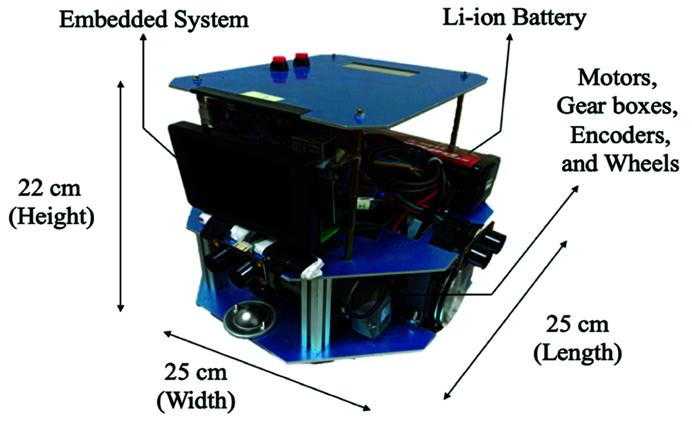
Figure 11: The appearance of the designed mobile robot
Furthermore, the vision system contains an RGB camera, with a light weight of 55 g and a horizontal angle of view (AOV) of 70 degrees, to cooperate with the ArUco markers for localization of the obstacles. The frame rate and the image resolution of the RGB camera are 30 frame-per-second (FPS) and 1920 × 1080 pixels, respectively. As being capable of detecting objects at the farthest distance of 10 meters, the RGB camera can be certainly applicable to the experimental environment with an area of 4 × 4 m2.
In the experiments, each cell is sized in a square of 40 cm × 40 cm, and then the entire experimental environment for the robot will be sized as 400 cm × 400 cm. The ArUco visualization system is employed to locate the obstacles, which are received by the proposed algorithm to solve the path planning, the feasibility of which is proved for the whole system in three proposed scenarios. The entire experimental procedure is divided into several single steps beginning from the start to the end positions of the mobile robot, as shown in Figs. 12a, 13a and 14a, which denote the results that the mobile robot is navigated to the destination with three, ten, and twenty obstacles, respectively. On all steps in Figs. 12a, 13a and 14a, the red arrows and yellow numbers indicate the current positions of the mobile robot and the running steps, respectively. For example, Step 1 means the robot just leaves the starting point at the lower-left corner, while Step 9 indicates the robot reaches the ending point at the upper-right corner. While the red simulated pre-planned and blue actual paths are presented in Figs. 12b, 13b, and 14b, respectively for the scenarios with three, ten, and twenty obstacles. The simulation results offer the pre-planned paths of all scenarios under the occurrence that the GA converges at a Pareto front with 2000 generations, considered as a pre-defined stop criterion of the GA, to offer the valid obstacle-avoidance routes for all of the scenarios.

Figure 12: The simulations and experimental results for the environment with three obstacles (a) The steps to navigate the robot to the ending point (b) Path comparison of simulation and experimental results

Figure 13: The simulations and experimental results for the environment with ten obstacles (a) The steps to navigate the robot to the ending point (b) Path comparison of simulation and experimental results

Figure 14: The simulations and experimental results for the environment with twenty obstacles (a) The steps to navigate the robot to the ending point (b) Path comparison of simulation and experimental results
There are two observations by comparing of the simulated pre-planned and actual paths for the mobile robot with three, ten, and twenty obstacles in Figs. 12b, 13b, and 14b, respectively. Firstly, the root-mean-square errors (RMSE) of actual path deviating from the pre-planned path are 3.6 cm, 5.1 cm, and 5.8 cm, respectively for three, ten, and twenty obstacles. The resulted RMSE suggests that the mobile robot will not exceed the border of the desired cell on the pre-planned path because the margin between the edge of the mobile robot and the border of the cell is 7.5 cm on average, which is safe within the margin from the robot to the cell border and can be accordingly deemed tolerable in this work. Here, the margin of 7.5 cm results from the fact that the width and length of the robot are both 25 cm, and the side length of a cell is 40 cm. Secondly, a major portion of the RMSE existing between the actual paths and the pre-planned paths is caused by the issue that most of the deviations between the two paths occur when the mobile robot is turning itself into another direction with a large angle. It might be incurred by the circumstance that the current mechanism of trajectory tracking is not robust enough for the mobile robot to execute an accurate turn due to the improper amount of the slipping friction between the tires of mobile robot and the ground. There remains certain work to be carried out to solve this problem in order to further improve the ability of path tracking for the mobile robot. In spite of the two issues mentioned above, it can be still verified that the experimental results well agree with the simulation results when they have the same initial conditions.
This work proposes a novel MOEA-based approach, consisting of a grid-based map with the low-cost gene encoding and the elite survivor selection via the NSGA-II, to search a collision-free path for a mobile robot to avoid static obstacles, which are localized by the ArUco system by means of a camera at bird’s view. For all of the test scenarios, the simulation results of the Pareto fronts show the convergence occurs when the number of generations arrives at 2000, and the experiments are conducted to prove the feasibility of the whole system. In conclusion, the proposed approach is practicable in a real-world application, under the requirements of a low speed and a limited working field.
There are two major limitations in this work: (1) Due to the low-end hardware in the embedded system of the mobile robot, the proposed algorithm currently runs on the console laptop with fast computing efficiency. (2) The dynamic behaviors of the mobile robot are not considered in this work, so the proposed approach is not suitable for the mobile robot to operate on tough venues, such as stages, hills, sands, etc. Accordingly, it remains for the future work to study how to improve the current algorithm via faster evolutionary operators, which can run on a mobile robot without the need of a high-cost centralized scheme. Besides, developing a robust motion control system can provide the mobile robot with the ability to overcome the existing nonlinearity and then to fit complex places in a real world. It is foreseen that the proposed robotic system will be employed in a commercial ball-collecting or object-carrying robot.
Acknowledgement: This research was partially sponsored by the Ministry of Science and Technology, Taiwan, under contract numbers MOST 109-2221-E-007-041.
Funding Statement: The authors received no specific funding for this study.
Conflicts of Interest: The authors declare that they have no conflicts of interest to report regarding the present study.
1. H. Jahanshahi and N. N. Sari, “Robot path planning algorithms: A review of theory and experiment,” arXiv preprint, arXiv:1805.08137v3 [cs.RO], 2018. [Google Scholar]
2. J. C. Latombe, in Robot Motion Planning, New York, USA: Springer, 1991. [Google Scholar]
3. B. Chanclou and A. Luciani, “Global and local path planning in natural environment by physical modeling,” in Proc. of IEEE/RSJ Int. Conf. on Intelligent Robots and Systems, vol. 3, Osaka, Japan, pp. 1118–1125, 1996. [Google Scholar]
4. E. Kagan, N. Shvalb and I. Ben-Gal, “Autonomous Mobile Robots and Multi-Robot Systems,” in Motion-Planning, Communication, and Swarming, John Wiley & Sons, 2019. [Google Scholar]
5. A. Lakhan, M. S. Memon, Q. Mastoi, M. Elhoseny, M. A. Mohammed et al., “Cost-efficient mobility offloading and task scheduling for microservices IoVT applications in container-based fog cloud network,” Cluster Computing, 2021. [Google Scholar]
6. P. E. Hart, N. J. Nilsson and B. Raphael, “A formal basis for the heuristic determination of minimum cost paths,” IEEE Transactions on Systems Science and Cybernetics, vol. 4, no. 2, pp. 100–107, 1968. [Google Scholar]
7. A. Stentz, “Optimal and efficient path planning for partially-known environments,” in Proc. of the 1994 IEEE Int. Conf. on Robotics and Automation, vol. 4, San Diego, USA, pp. 3310–3317, 1994. [Google Scholar]
8. S. Koenig and M. Likhachev, “Incremental A*,” Advances in Neural Information Processing Systems, vol. 14, Vancouver, Canada, pp. 1539–1546, 2001. [Google Scholar]
9. A. Martinez, E. Tunstel and M. Jamshidi, “Fuzzy logic based collision avoidance for a mobile robot,” Robotica, vol. 12, no. 6, pp. 521–527, 1994. [Google Scholar]
10. J. -Y. Potvin, “Genetic algorithms for the traveling salesman problem,” Annals of Operations Research, vol. 63, pp. 339–370, 1996. [Google Scholar]
11. C. T. C. Arsene and A. M. S. Zalzala, “Control of autonomous robots using fuzzy logic controllers tuned by genetic algorithms,” in Proc. of the 1999 Congress on Evolutionary Computation, vol. 1, Washington, USA, pp. 428–435, 1999. [Google Scholar]
12. K. Deb, “Multi-objective optimisation using evolutionary algorithms: An introduction,” in Multi-objective Evolutionary Optimisation for Product Design and Manufacturing, London, UK: Springer, pp. 3–34, 2011. [Google Scholar]
13. H. Monsef, M. Naghashzadegan, A. Jamali and R. Farmani, “Comparison of evolutionary multi objective optimization algorithms in optimum design of water distribution network,” Ain Shams Engineering Journal, vol. 10, no. 1, pp. 103–111, 2019. [Google Scholar]
14. M. Song and D. Chen, “A comparison of three heuristic optimization algorithms for solving the multi-objective land allocation (MOLA) problem,” Annals of GIS, vol. 24, no. 1, pp. 19–31, 2018. [Google Scholar]
15. W. Chen, J. Zhang, H. Chung, W. Zhong, W. Wu et al., “A novel set-based particle swarm optimization method for discrete optimization problems,” IEEE Transactions on Evolutionary Computation, vol. 14, pp. 278–300, 2010. [Google Scholar]
16. J. Kennedy and R. Eberhart, “A discrete binary version of the particle swarm algorithm,” in Proc. of 1997 IEEE Int. Conf. on Systems, Man, and Cybernetics, Orlando, USA, vol. 5, pp. 4104–4108, 1997. [Google Scholar]
17. C. H. Yun, Y. Moon and N. Y. Ko, “Vision based navigation for golf ball collecting mobile robot,” in Proc. of 2013 13th Int. Conf. on Control, Automation and Systems, Gwangju, Korea, pp. 201–203, 2013. [Google Scholar]
18. A. Rechy Romero, P. V. Koerich Borges, A. Elfes and A. Pfrunder, “Environment-aware sensor fusion for obstacle detection,” in Proc. of 2016 IEEE Int. Conf. on Multisensor Fusion and Integration for Intelligent Systems, Baden-Baden, Germany, pp. 114–121, 2016. [Google Scholar]
19. M. Intisar, M. M. Khan, M. R. Islam and M. Masud, “Computer vision based robotic arm controlled using interactive GUI,” Intelligent Automation & Soft Computing, vol. 27, no. 2, pp. 533–550, 2021. [Google Scholar]
20. S. Garrido-Jurado, R. Muñoz-Salinas, F. J. Madrid-Cuevas and M. J. Marín-Jiménez, “Automatic generation and detection of highly reliable fiducial markers under occlusion,” Pattern Recognition, vol. 47, no. 6, pp. 2280–2292, 2014. [Google Scholar]
21. S. Garrido-Jurado, R. Muñoz-Salinas, F. J. Madrid-Cuevas and R. Medina-Carnicer, “Generation of fiducial marker dictionaries using mixed integer linear programming,” Pattern Recognition, vol. 51, pp. 481–491, 2016. [Google Scholar]
22. F. J. Romero-Ramirez, R. Muñoz-Salinas and R. Medina-Carnicer, “Speeded up detection of squared fiducial markers,” Image and Vision Computing, vol. 76, pp. 38–47, 2018. [Google Scholar]
23. B. Xing, Q. Zhu, F. Pan and X. Feng, “Marker-based multi-sensor fusion indoor localization system for micro air vehicles,” Sensors, vol. 18, pp. 1706–1724, 2018. [Google Scholar]
24. F. Sonnleitner, R. Shu and R. L. Hollis, “The mechanics and control of leaning to lift heavy objects with a dynamically stable mobile robot,” in Proc. of 2019 IEEE Int. Conf. on Robotics and Automation, Montreal, Canada, pp. 9264–9270, 2019. [Google Scholar]
25. X. Zhang, A. Liniger and F. Borrelli, “Optimization-based collision avoidance,” arXiv preprint, arXiv: 1711.03449v3 [math.OC], 2018. [Google Scholar]
26. O. al jaddan, L. Rajamani and C. R. Rao, “Improved selection operator for GA,” Journal of Theoretical and Applied Information Technology, vol. 4, pp. 269–277, 2008. [Google Scholar]
27. K. Deb, A. Pratap, S. Agarwal and T. Meyarivan, “A fast and elitist multiobjective genetic algorithm: NSGA-II,” IEEE Transactions on Evolutionary Computation, vol. 6, no. 2, pp. 182–197, 2002. [Google Scholar]
28. A. Morar, A. Moldoveanu, I. Mocanu, F. Moldoveanu, I. E. Radoi et al., “A comprehensive survey of indoor localization methods based on computer vision,” Sensors, vol. 20, no. 9, 2641, pp. 2020. [Google Scholar]
29. A. Zakiev, T. Tsoy, K. Shabalina, E. Magid and S. K. Saha, “Virtual experiments on arUco and aprilTag systems comparison for fiducial marker rotation resistance under noisy sensory data,” in Proc. of 2020 Int. Joint Conf. on Neural Networks, Glasgow, UK, pp. 1–6, 2020. [Google Scholar]
30. W. Garage, A. Blasdel, A. Leeper, C. Rockey, D. Stonier et al, Robot Operating System. [Online]. 2018. Available: http://www.ros.org/. [Google Scholar]
 | This work is licensed under a Creative Commons Attribution 4.0 International License, which permits unrestricted use, distribution, and reproduction in any medium, provided the original work is properly cited. |