DOI:10.32604/iasc.2022.022370
| Intelligent Automation & Soft Computing DOI:10.32604/iasc.2022.022370 | |
| Article |
Three to Six Phase Power Converter with Partial Resonant AC Link
1Department of EEE, Kalasalingam Institute of Technology, Srivilliputhur, 626128, India
2Department of EEE, Mepco Schlenk Engineering College, Sivakasi, 626005, India
*Corresponding Author: V. Ravikumar. Email: ravikumar224498@gmail.com
Received: 05 August 2021; Accepted: 29 September 2021
Abstract: A six phase system is a balanced multiphase system that can be replace, in certain applications, the three phase system and the application becomes much fault tolerant. In the six phase system a phase angle of 60 degrees is maintained between the phases. Handling power with more number of phases reduces the maximum current in each of the phase in the system. In this work a six phase balanced AC output is derived from a three phase AC source. The proposed system uses a resonant single phase AC link driven by a three phase bidirectional converter unit AC link is feeding for a single phase to six phase bidirectional converter. The proposed methodology is a general purpose electronic three phase to six phase conversion system, suitable for applications such as six phase induction motor. Also, it can be used as the front end power conversion stage for a six phase PMSG based wind energy harvesting system, and used for the fault tolerant STATCOM units. The proposed system can replace the conventional STAR/STAR and STAR/DELTA three phase transformer combination systems needed for 12 pulse rectifiers used in HVDC. The proposed system has been validated using simulations in the MATLAB SIMULINK environment and the relevant experimental verification.
Keywords: Multiphase system; MATLAB SIMULINK; matrix converter; power quality
The six phase system preferable than a three phase system for certain applications [1]. A six phase induction motor is fault tolerant, produces more smooth torque than the power electronic driven three phase squirrel cage induction motor [2]. A six phase rectifier produces a dc output with less ripple magnitude. The current carrying capacity of the semiconductors and cables can be reduced in the six phase configuration than the three phase configuration of drives. In a six phase system, even if a phase fails the system continues to work with very small influence of the fault on the system operation [3]. Thus the six phase system is preferable to three phase system. However, the long distance transmission of six phases becomes more cumbersome and more costly than the three phase systems [4].
The advantages of polyphase systems are a polyphase transmission line requires less conductor material, polyphase machine gives a higher output, polyphase motors have a uniform torque, polyphase induction motors are self-starting and are more efficient, per unit of output of the polyphase machine is very much cheaper, power factor is high, Parallel operation of polyphase alternators is simple.
The 3 phase power generating and delivering is more efficient than 2 phase which in turn is more efficient than 1 phase. Similarly, going up in the number of phases result in increased efficiency as well, i.e., 4 phase is more efficient than 3 phase, 5 phase is more efficient than 4 phase and 6 phase is more efficient than 5 phase, etc. The increase of efficiency as the number of phases increase is attributed to that power delivery becomes more continuous as the number of phases increases. For standalone applications, the three phase to six phase converters, or the single phase to six phase converters and back could be very much useful [5].
Since the generation and transmission in the national network is of the three phase model the conversion to six phase system should be done by power electronic converters [6]. The development of the stator winding of six phase induction motors, the six phase generators and transformers do not exhibit much complicated mathematical issues as compared to the solid state version of the three phase to six phase conversion schemes that are implemented using power electronic switches.
A Matrix converter that is meant to convert from three phase system of voltages to six phase system of voltages can be used to drive the six phase induction motor. It can also be used to harvest power from a wind turbine driven six phase induction generator or the PMSG with six phases [7]. The direct Matrix converter with a 3 by 6 configuration is suitable for the purpose. That could be operating with bidirectional conversion system suitable for this purpose [8]. The conventional matrix converter suffers resonant AC link overcomes most of the existing issues associated with the different Matrix converter schemes [9].
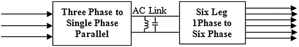
Figure 1: The block diagram of the proposed three phase to six phase ac converter through link
The conventional matrix converter does not include any storage element hence is more compact and can be realized as direct semiconductor packages with reduced footprint. On the other hand, the back to back conversion scheme from N phases to M phases requires a DC link. Although the system includes a DC link capacitor and becomes bulky and reduced overall life, the back to back converter offers independent control of the power electronic converter on either side of the dc link [10]. There is no need of a combined switching strategy for the input and the output side [11].
In a back to back converter, the converter on the input side acts as a rectifier and that on the output side acts as an inverter. The constraints of operation of the rectifier and the inverter are different [12]. The source side converter draws power from a multi-phase AC source. The source current should be balanced, sinusoidal and it should be in phase with the respective source voltage phases [13].
The responsibilities of the inverter on the load side are that it produces a harmonic free multiphase balanced AC voltage or current output at the appropriate frequency, amplitude and with the appropriate angular displacements between the phase’s voltages [14]. The output voltage should be consistent against different loading and the source side disturbances. In such power conversion systems passive filters of appropriate configuration are also usually included on both the input and load sides [15].
The proposed resonant AC link matrix converter, the block diagram of which is shown in Fig. 1 can produce M phase outputs from N phase inputs. The output voltage Vout can be more than Vin. The source and load side converter stages could be controlled independently. The proposed system is modeled and validated using the MATLAB SIMULINK platform. An experimental verification prototype has also been developed and demonstrated. Unlike the conventional back to back converter, the proposed system does not require a bulky DC link capacitor [16]. Instead, there is a resonant, AC link which consists of an inductor and a capacitor in parallel with the resonant single phase AC bus.
The paper has been arranged as follows. An introduction is given in this section. Following this introduction of the direct matrix converter is explained. The methodology of generating the switching pulses for a six phase inverter with six legs of bidirectional switches have been demonstrated in the next section. A section to present the details of the experimental verification is given next. Then in the following chapter the results of simulations experimental verifications are discussed. The conclusion and the reference sections then follow.
A direct Matrix converter uses a set of 9 bidirectional switches arranged in the form of 3 rows and 3 columns. Each of the bidirectional switch module could be realized as a set of two back to back connected power electronic switches like the MOSFETs or the IGBTs.
2.1 Direct Matrix Converter and Space Vector Modulation
The topology of the Matrix converter is shown in Fig. 2. The objective of such a matrix converter [17] is usually to generate a three phase variable voltage variable frequency output from a three phase fixed frequency and fixed voltage input. In conventional back to back converter, the proposed system does not require a bulky DC link capacitor. Instead, there is a resonant, AC link which consists of an inductor and a capacitor in parallel with the resonant single phase AC bus.
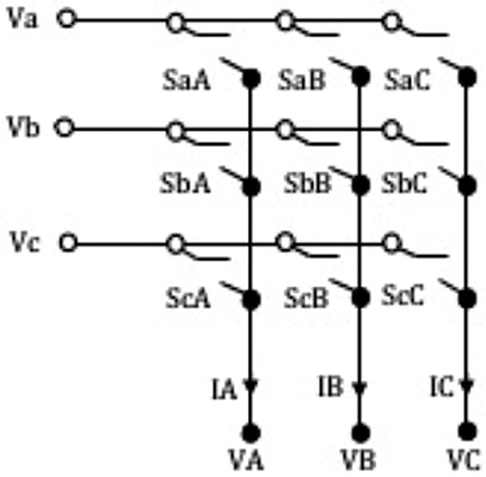
Figure 2: The topology of the general 3 * 3 matrix converter
Throughout the operation of such a matrix converter, it is the input current that is to be controlled for delivering the required variable voltage variable frequency three phase output. For the given amplitude and frequency of the input voltage, for any output power delivered, at whatever frequency and amplitude of the output voltage, it is the amplitude of the input current that is altered in real time in such a manner that the input side current is of sinusoidal wave shape with appropriate amplitude and is in phase with the source side voltage so that the required power is delivered to the load and that the source side power factor [18] is also unity. These requirements are usually met with the combined effort of the power electronic switches of the Matrix converter and the passive filter elements on the input and the output side of the matrix converter.
The selection of the passive filter units is based on the switching frequency and the switching strategy adopted. A high switching frequency reduces the size of the passive filter elements at the cost of increased switching losses. Depending upon the exact application, the filters will be designed with following factors in mind: initial cost, running cost, loss and power quality conscious.
2.2 The Space Vector Modulation
The space vector pulse width modulation (SVPWM) is a pulse width modulation technique applicable for multiphase inverters. The SVPWM technique belongs to the high switching frequency category of PWM. However it does not use an explicit carrier. The SVPWM uses a mathematical procedure using which the switching pulses are produced. The SVPWM methodology uses a geometrical basis that makes it possible to develop balanced switching pulses for an N phase inverter. The number of switches to be turned ON or OFF at any instant of time are formed in a vector and the vector is known as the switching vector.
In the case of the three phase three leg inverter, the upper and lower switches of each leg, that are turned ON are denoted as 1 and 0. In respect of the three legs if the bit pattern is 111 then the switches in the upper arm for all the three legs are in the ON state and similarly the pattern 000 means the lower switches in all the three legs are ON. Since there are 3 legs eight combinations are possible. Out the eight combinations the patterns 111 and 000 are known as the NULL vectors while other combinations are active vectors. Depending upon each of the active vector the three nodes of the three phase inverter are connected to either the upper or positive rail or to the lower or negative rail of the DC bus bar. When any if the NULL vector is maintained the three nodes are simultaneously connected to the positive rail or the negative rail so that the inter node potential difference becomes zero making the line to line voltage zero.
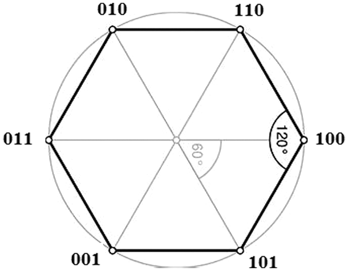
Figure 3: The space of the hexagon in which the switching vectors are at the vertices
Since there are six active vectors, these six active vectors could be shown to be the vertex of a hexagon as shown in Fig. 3. The space vector pinned to the origin rotates about a circle and this rotating space vector eventually passes on in a circular pattern and passes through the six vertices.
A three phase balanced system of voltages can be transformed into a two phase orthogonal system of voltages. This relationship is referred to as the Clark transformation and is given by the Eq. (1).
The three voltages Va, Vb and Vc are balanced sinusoidal waves displaced by 120 degrees. The two voltages Vα and Vβ given by Eq. (1) are two sinusoidal voltages and are displaced by 90 degrees. The resultant of these two orthogonal sinusoidal waves is a single rotating vector.
Thus a three phase balanced system of voltages or currents can be represented by a single vector that rotates in a circular fashion. The locus of the tip of the rotating space vector is the circle. The length of the rotating space vector is a function of the amplitude of the three phase balanced system of voltages or currents as the case may be. In the consideration of a voltage source inverter the length of the space vector represents the three phase voltages and the speed at which the rotating space vector rotates around is dictated by the frequency of the voltage system. If the system frequency is 50 Hz then the space vector takes 20 milliseconds to complete one circle.
As the rotating space vector moves around a circle as shown Fig. 4, it moves past the six voltage vectors, at times aligning with the six active vectors possible. The area between each voltage vector is known as a sector. During the travel of the space vector the space vector dwells in each sector
A rotating space vector (RSV) represents a three phase balanced continuous sinusoidal three phase system. Even though the rotating space vector moves around in a continuous fashion for a continuous three phase sinusoidal system, as for one three phase inverter is concerned, which is realized using discretely switched power electronic switches in this case, the rotating space vector rotates in a circle with discrete steps over the 360 degrees, resting in each step for a finite time.
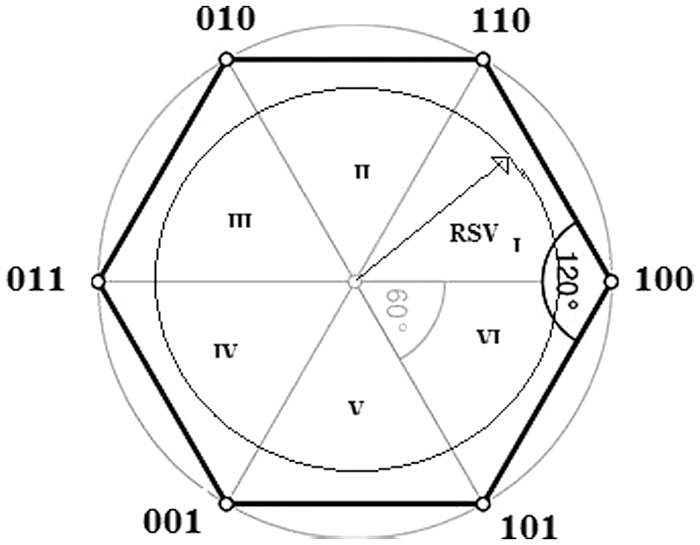
Figure 4: The rotating space vector the state in the state space
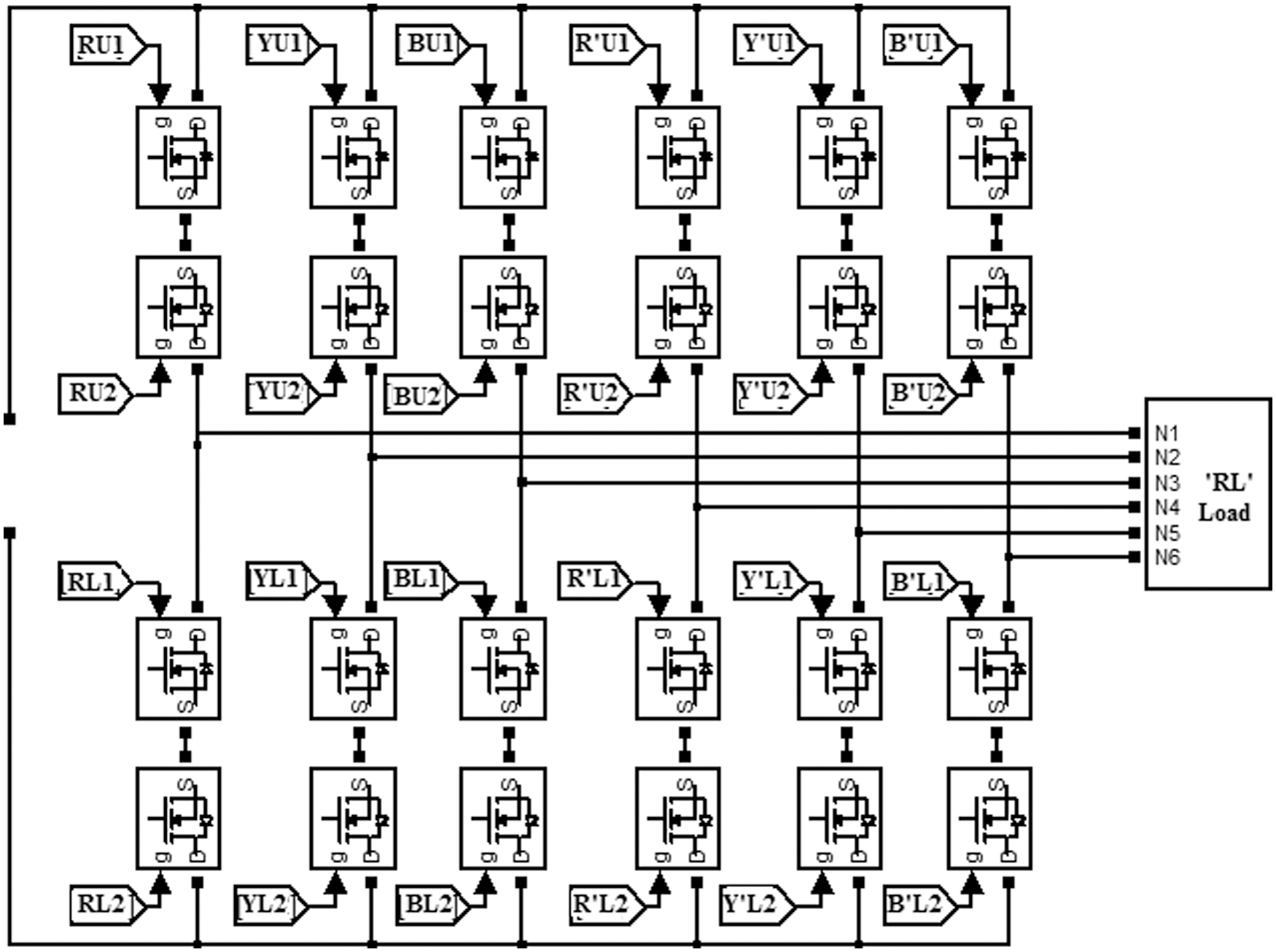
Figure 5: The six phase converter unit with bidirectional switches switched power electronic switches
The SVPWM technique of generating switching pulses as applicable to the three phase inverter can be extended for the six phase inverter as well. As shown in Fig. 5, the six phase inverter has six legs with two Switching modules in each leg. Each switching module has back to back connected MOSFETs. There are six nodes from where the six phase AC output can be derived out. In the basic form, the DC supply is impressed across the DC rails. The turned on condition of a power electronic switch module in the high voltage side in each leg is denoted as 1 and the turned on condition of the lower switches are denoted by a 0. Since there are six legs, a string if six bits can be used to represent the state of switching.
Although six legs with two MOSFETs in each leg is enough, since we intend to drive the six phase inverter using an AC source the bidirectional switching arrangement is necessary.
The switching state is shown as a switching vector. When all the upper switches in each leg are turned on the switching vector is [1 1 1 1 1 1] and similarly the vector [0 0 0 0 0 0] represents that all the six lower switches are turned on. These two vectors [1 1 1 1 1 1] and [0 0 0 0 0 0] cannot deliver any voltage output and hence they are known as the null vectors. The other combinations can deliver AC output voltage. The magnitude of the output voltage at any instant, at each node with respect to other nodes is decided by the switching vector [a b c d e f].
Since there are 6 bits, a set of 64 combinations are possible. Out of these, eliminating the 2 null vectors 62 vectors can be used. In the proposed method, the six phase system is considered to be consisting of two three phase systems denoted as R Y B and R' Y' B'. The six legs of the proposed inverter are numbered 1, 2,3,4,5 and 6. The legs 1,3,5 are used for the first bridge to produce RYB output. The legs 2,4,6 are used to produce R'Y'B'. The phase difference between the output at nodes R Y B are maintained at 120 degrees. The phase difference between the nodes R' Y' and B' are maintained at 120 degrees. The phase difference between nodes R and R', Y and Y' as well as B and B' are maintained at 60 degrees
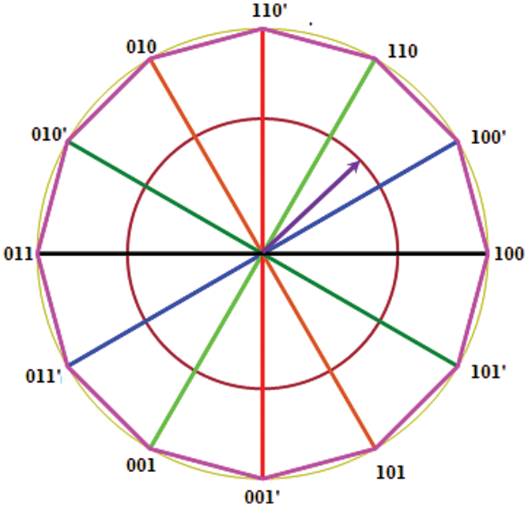
Figure 6: The position of the 12 voltage vectors
Thus the voltage outputs at all the nodes are displaced from the adjacent nodes by 60 degrees. In a three phase inverter, the combinations 100,110,010,011,001,101 are changed over at 60 degrees. The shift between the rotation of the first three first set and the interleaved second set is 30 degrees. The voltage vectors of the six phase inverter are shown in Fig. 6. The switching is formed in this consideration and is as shown in Tab. 1
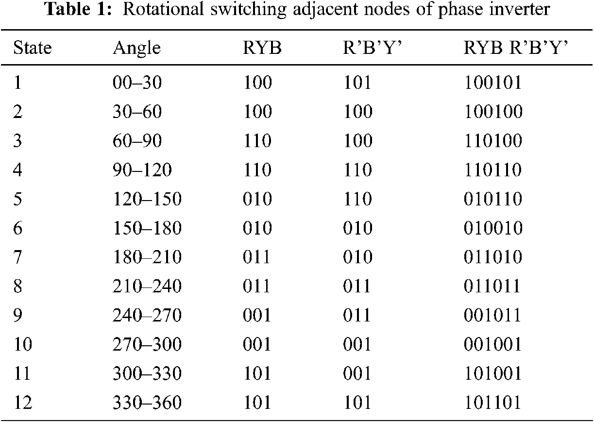
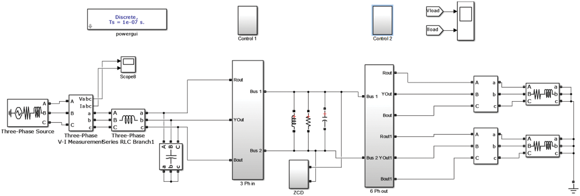
Figure 7: The MATLAB SIMULINK realization of the proposed system
4 The Overall Scheme of the Proposed Idea
The objective of the proposed system is to synthesize the six phase output voltage of the converter as shown in Fig. 7 while the corresponding source current waveform is shown in Figs. 8a and 8b.
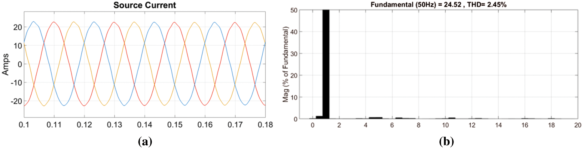
Figure 8: (a) The three phase source current (b) The FFT of R phase of the source current
There are two possibilities of generating the switching pulses for a six phase inverter. In the first method a single rotating space vector is realized for the six phase system by considering the requirement as described by Eq. (2).
With reference to Eq. (2) a common alpha beta components are identified and a single rotating space vector is found. Based on the rotation of this single space vector in the plane of a double hexagon with 12 vertices, as shown in Fig. 6, the appropriate voltage vectors are selected and these vectors are considered for the synthesis of the six phase voltage waveform.
In the second method which is followed in this work, as described by Eqs. (3) and (4), two sets of three phase SVPWM based switching pulse generation are used.
The RYB and the R' Y' B' output phases are then interleaved with the first set The second set of SVPWM is produced with a phase delay of 60 degrees from the first set. For this purpose, two three phase reference signals are used.
The two sets of reference signals are actually three phase voltage reference signals. Set one consists of RYB and set two consists of R’Y’B’. The phase angle between the individual phases of RYB as well as R’Y’B’ are 120 degrees. The phase angle between phases R and R’, Y and Y’ and B and B’ are uniformly 60 degrees.
The proposed system uses a set of two Space Vector Modulation units. For the first unit, the reference set RYB are applied while for the second set R’Y’ and B’ are applied. These references signals individually are alpha beta transformed and the rotating space vector are identified. The two rotating space vectors are individually processed in a set of two SVPWM subsystems and finally the switching pulses for the 12 switches are produced.
The SVPWM sub system used for the switching pulses generation for one of the two sets of three phase outputs is shown in Fig. 9. At the last stage of switching pulse generation unit, there is a set of three direct outputs and three inverted outputs. Conventionally, the direct output lines L1a, L2a and L3a are used for the upper set of switches in each leg. The lines L2a, L2b and L2c are used for the lower switches in each leg.
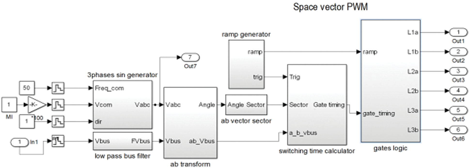
Figure 9: The SVPWM subsystems
With the conventional DC link replaced by the AC link, the selection of the upper or the lower switches are changed according to the polarity of the AC link. In order that power is transacted in either polarity of the AC link, bi directional conducting switching modules are used in the converter bridge.
A zero crossing detector is used to identify the polarity of the AC link and accordingly the switching modules are selected.
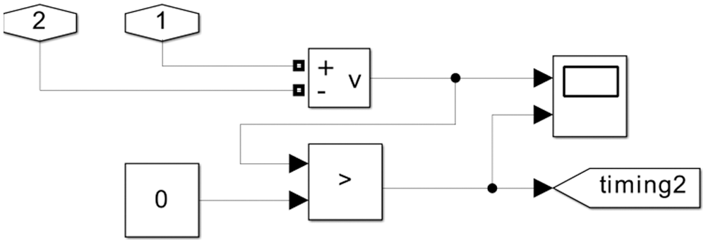
Figure 10: The zero crossing detector
Fig. 10 shows the Zero Crossing detector. The Zero crossing detector taken in the AC link voltage as input and delivers a square pulse with zero state corresponding to the negative cycle of the AC link and one state for the positive half cycle of the AC link voltage. Figs. 11 and 12 give the waveforms of the partial resonant AC link voltage and the corresponding Zero Crossing detector output. The Zero Crossing Detector output selects the upper or lower modules of switches of each legs of the six phase Matrix converter.
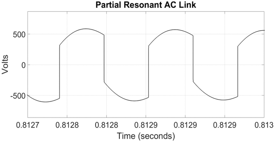
Figure 11: The partial resonant AC link voltage
Fig. 11 shows the partial resoant AC link votlage. This AC votlage at a resonant frequency of 8840 Hz is applied to the zero crossing detector shown in Fig. 10. The output of the ZCD is a square wave and it is shown in Fig. 12.
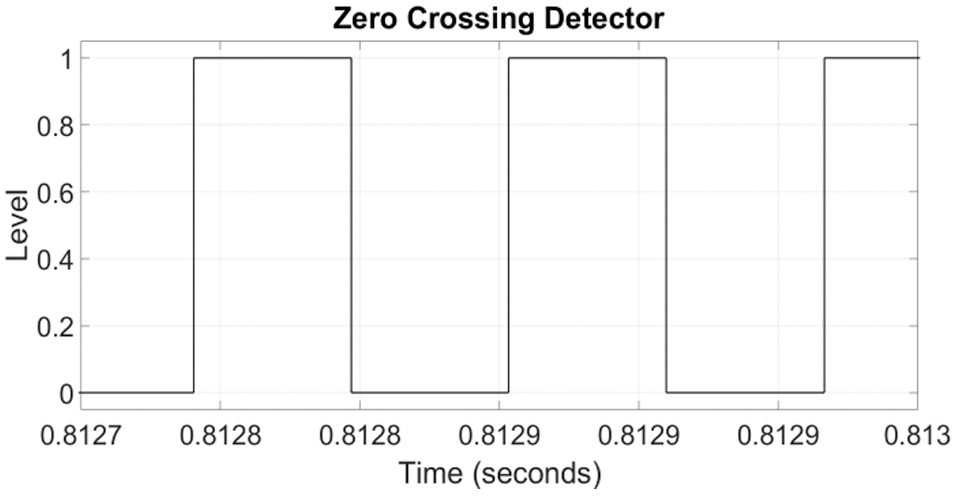
Figure 12: The output of the zero crossing detector
In the traditional space vector scheme applied for three phase inverters the six MOSFETs used are dirven by the pulses generted by the SVPWM section as shown in Fig. 13. This scheme is applicable only when the rails of the converter carries a DC link voltage. In this application the rails carry a resonant AC voltage. Therefore depending upon the polarity of the AC link voltage detected by the zero crossing detector, an inversion schem as shown in Fig. 14 is used. This scheme inverts the switchng pulse set depending upon the polarity of the AC link voltage.
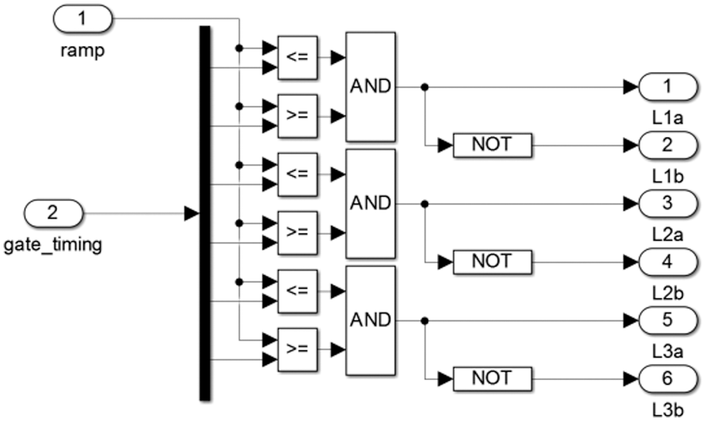
Figure 13: The direct and inverted switching pulse outputs
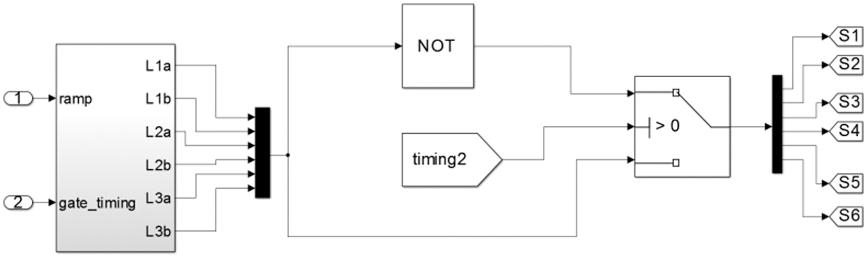
Figure 14: The switching pulse Inversion scheme to suit the AC link polarity
In this work there are two SVPWM modules. Each module produces a three phase output with the standard phase angle 120 degrees. These two modules inter leaved and phase shifted in such a manner that the phase difference between the phases R and R’ Y and Y’ and B and B’ are all 60 degrees. For each of the two SVPWM systems set of two three phase reference signals are used. Fig. 13 shows the output of the first SVPWM modules meant to drive the first set of three legs of the six leg converter. Fig. 15 shows two separate SVPWM modules meant for two independent three phase inverter modules are used. The two set of three phase reference signals are phase shifted by 60 degrees for each phase. These 12 pulses reach the six leg converter module as shown in Fig. 16.
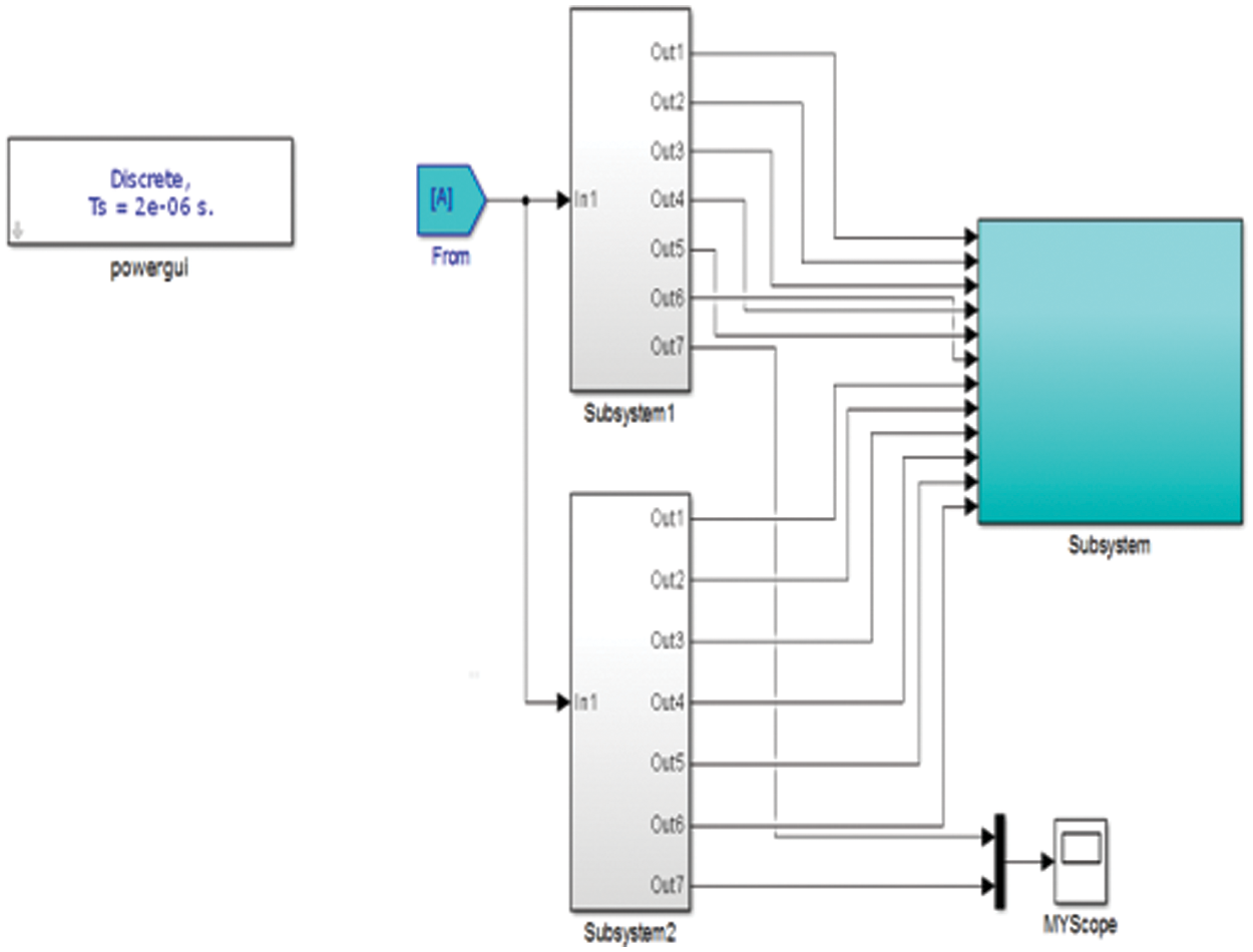
Figure 15: The switching pulse generation subsystems creating the 12 pulses
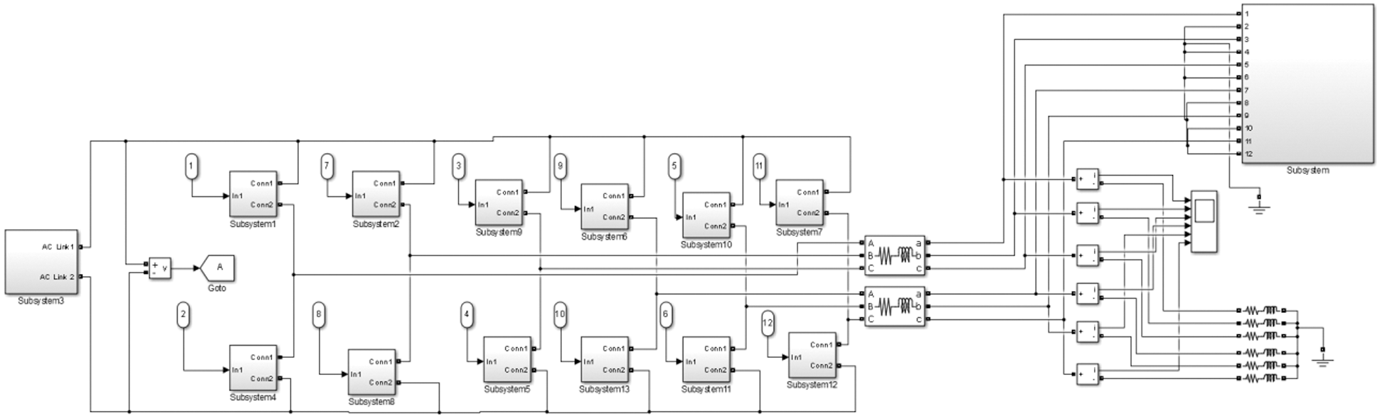
Figure 16: The MATLAB SIMULINK implementation of the six phase converter
The six phase voltage output of the proposed three phase to six converter is shown in Fig. 17. The phase voltages are phase shifted by 60 degrees. The modulation index used was 0.7. The corresponding six phase voltage output after the filter is shown in Fig. 18. The six phase load current with an RL load is shown in Fig. 19. The peak value of the load current is 10A while the peak value of the three phase source current is 20 A as shown in Fig. 8a. The THD of the source current is shown in Fig. 8b and is less than the maximum allowable 5%.
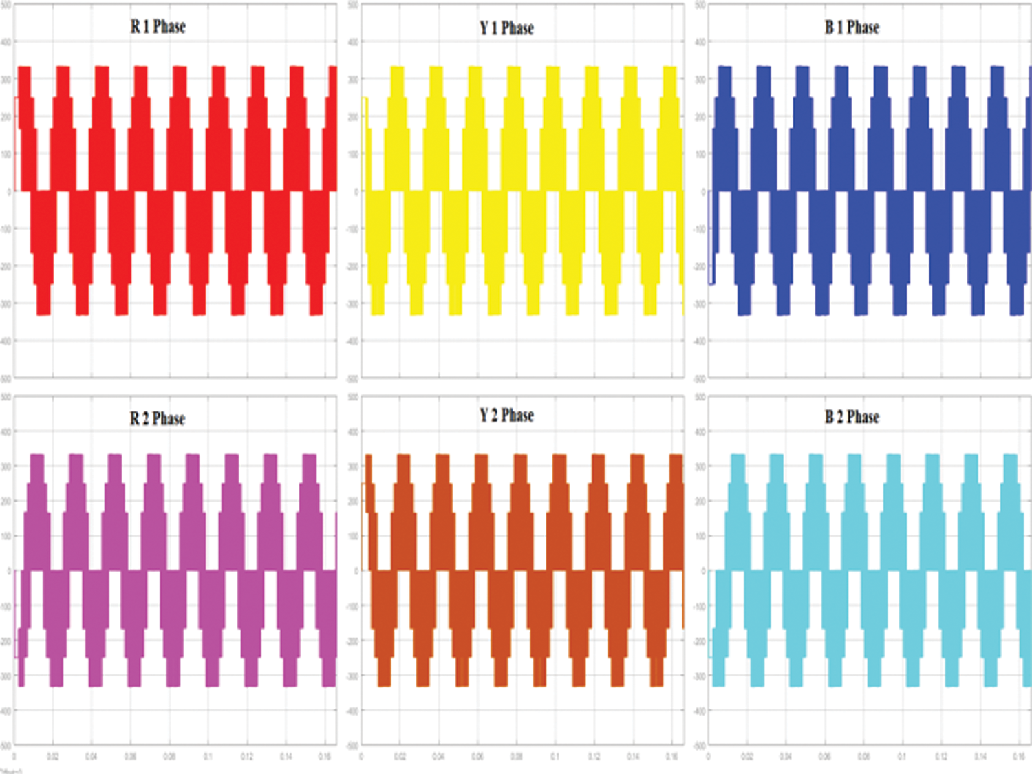
Figure 17: The unfiltered six phase voltage output
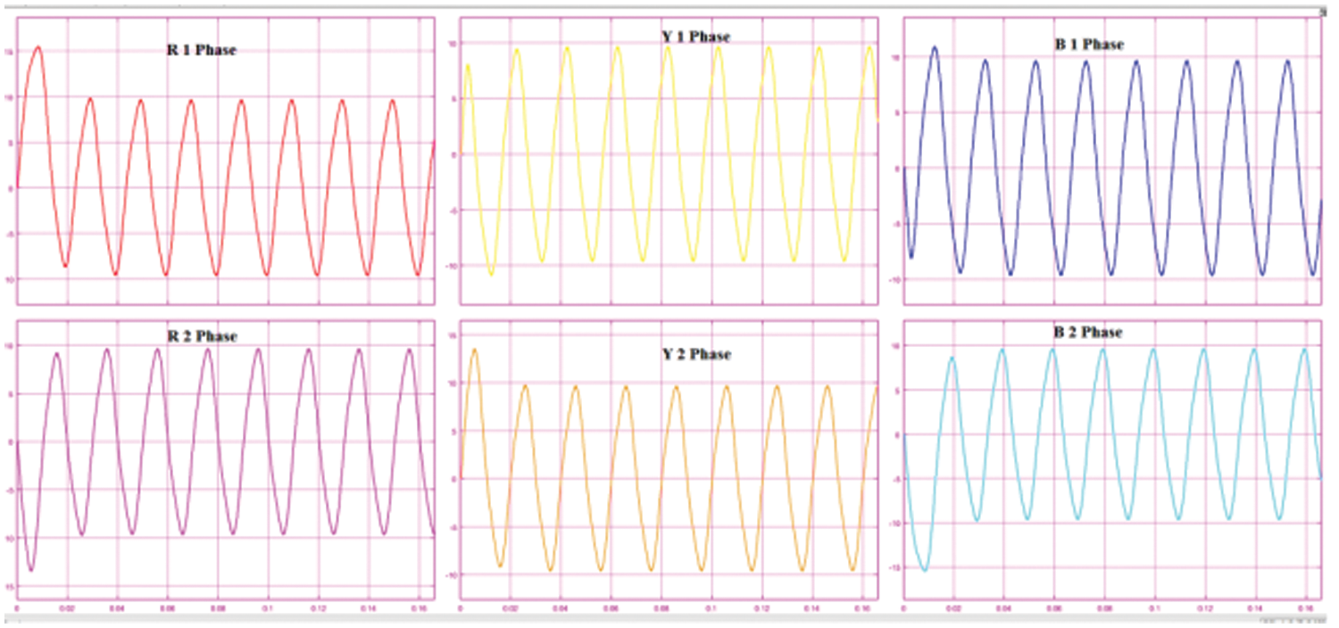
Figure 18: The filtered six phase voltage output
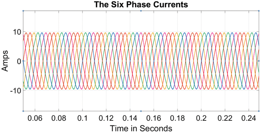
Figure 19: The six phase load current
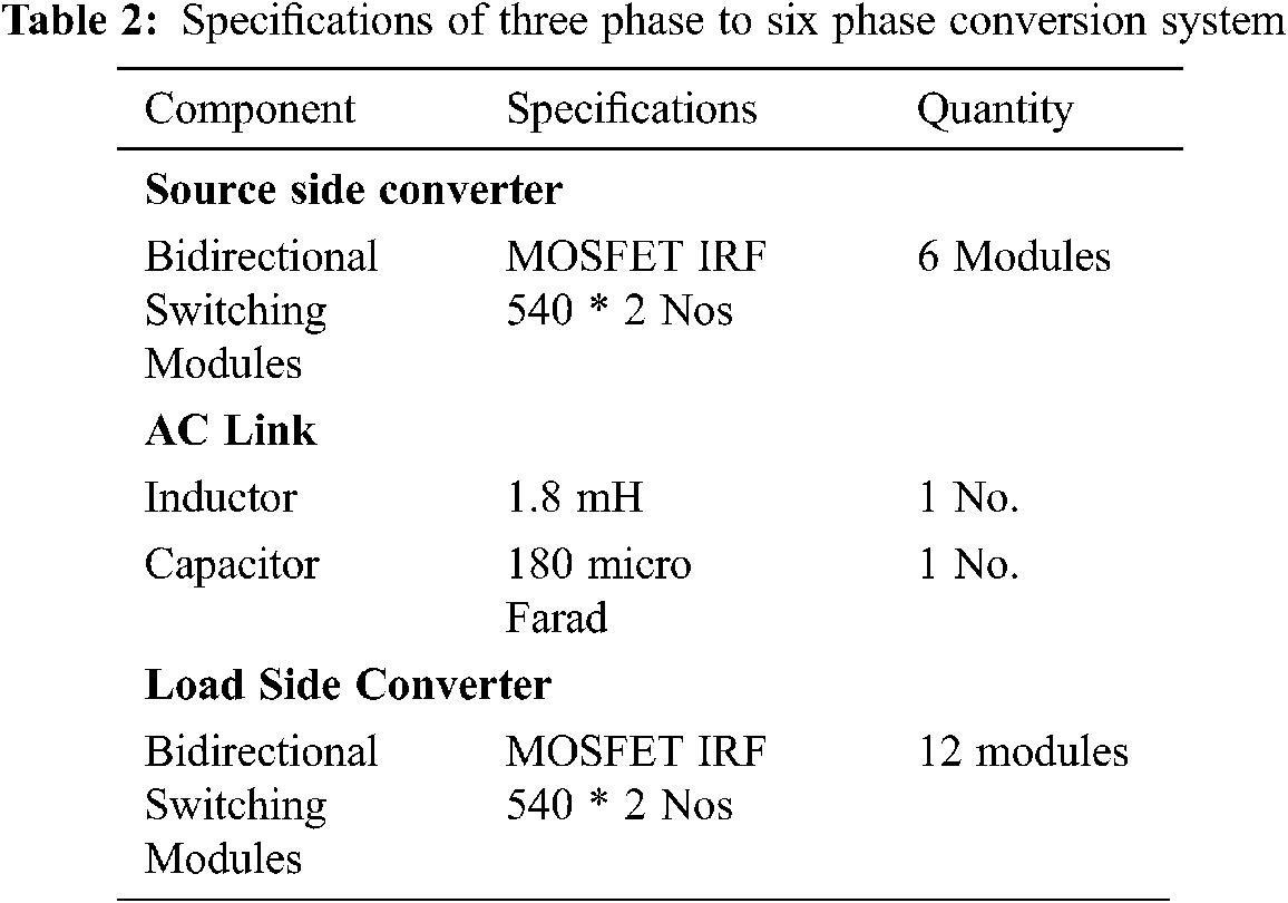
A prototype for the experimental verification of the proposed idea has been fabricated and the details of the prototype and the results obtained are presented in this section. The proposed system uses a three phase 50 Hz, 48 V Line to Neutral source. The 48 V three phase source has been derived using a set of three transformers connected in the STAR/STAR configuration. The rating of each of the transformers is 240 V/48 V 10 A with a VA rating of 480 VA.
The available three phase AC source is first converted into a higher frequency single phase resonant AC link. The three phase to single phase power conversion scheme consists of a three leg converter that draws power from the three phase AC system and delivers it to a high frequency AC link. The AC link consists of the resonant LC parallel circuit. The three phase to single phase converter uses bi directional switching modules in each arm of the three legs so that an AC output can be delivered across the LC circuit at the desired frequency.
Another power converter transfers power from the single phase resonant AC link to the six phase load. This second converter is a six leg converter with bidirectional switches in each of the upper and lower arms in each of the six legs.
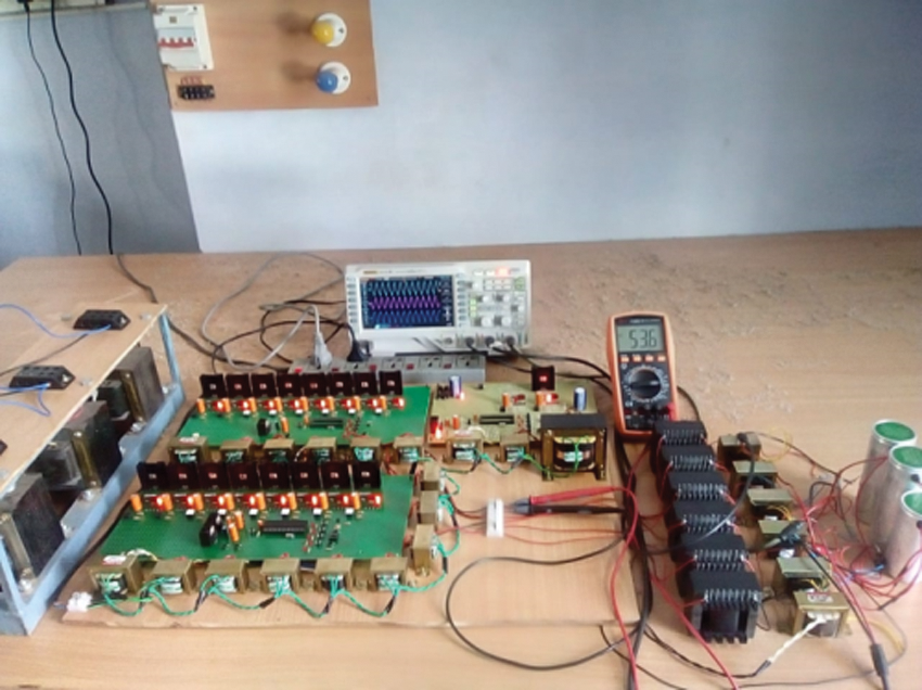
Figure 20: The photograph of the prototype
The specifications of the components used for the proposed three phase to six phase conversion system are shown in Tab. 2 and Fig. 20 shows the photograph of the prototype. The picture includes the three phase transformer to get the reduced three phase voltage of 48 V., the power electronic converter units, the LC filters for the three phase voltage output and the central micro controllers.
There are two PIC microcontrollers PIC16F877A used in the two Power electronic converter PCBs. The series connected MOSFETs are driven by the micro controllers through the opt coupler MCT2E. For powering up each of the MCT2E ICs in an isolated manner separate transformers are used. The important output signals are shown here in.
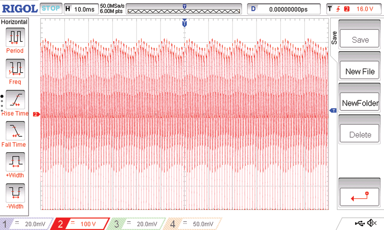
Figure 21: The voltage at the high frequency AC link
In the proposed system, the source side three phase voltage system is first converted into a single phase resonant AC link at a frequency of 1.8 KHz. The resonant frequency is dictated by the values of the L and C used, this switching frequency at the front end three phase to single phase converter is controlled by the PIC micro controller. The AC link frequency as recorded in the AC link is shown in Fig. 21. On the load side the six leg, twelve pulse converter generates the required six phase output and the six output phases are named as R R’ Y Y’ B and B’ with a phase shift of 120 degrees between R Y and B phases and a phase shift of 120 degrees between R’ Y’ and B’. The phase shift between R and R’; Y and Y’; B and B’ are 60 degrees.
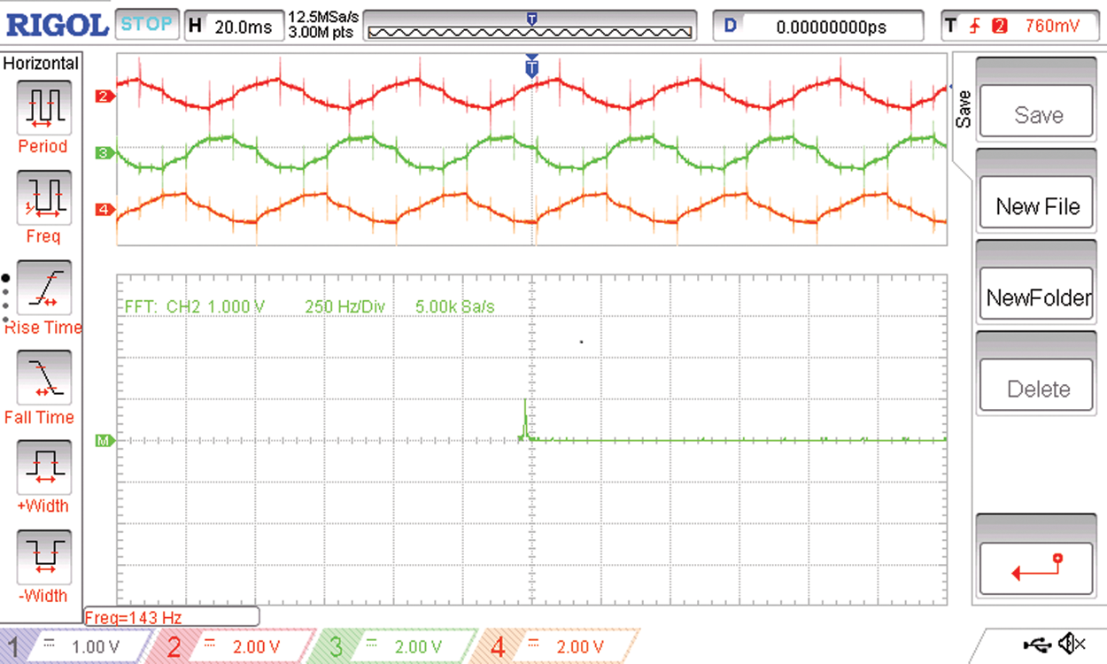
Figure 22: The load side voltages of the first three phases R R’ Y and the spectrum of the R phase

Figure 23: The load side voltages of the second three phases Y’ B and B’ with the spectrum of the Y’ phase
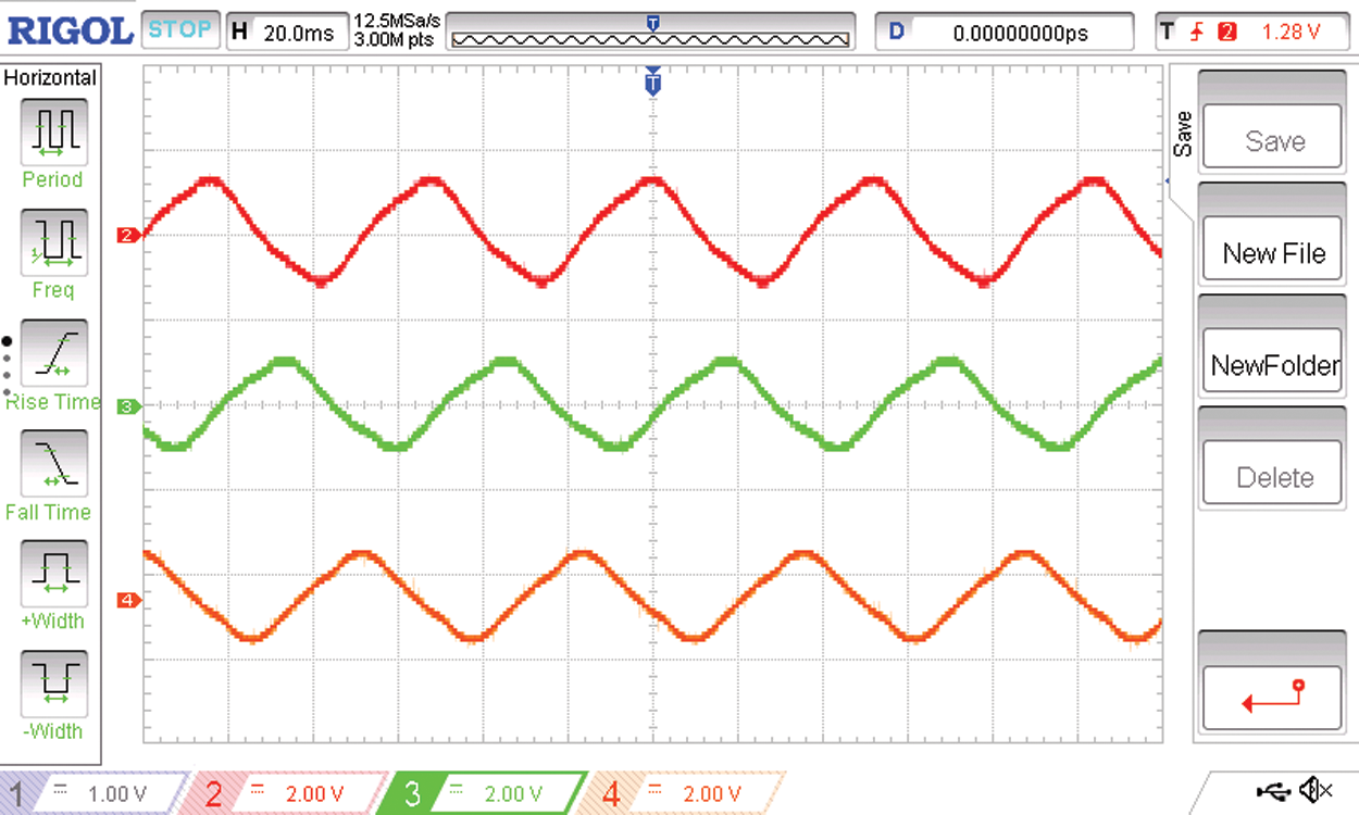
Figure 24: The filtered three phase source currents R Y B
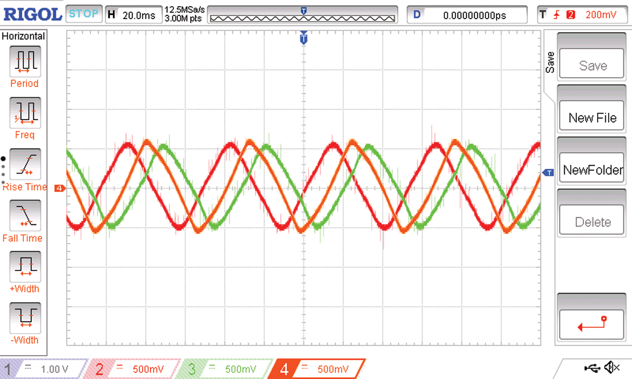
Figure 25: The 60 degrees phase shifted three phases R R’ and Y of the six phase load current
Figs. 22 and 23 shows the voltage waveforms of the two sets of three phases of the six phase voltage output of the proposed three phase to six phase conversion system with the spectrum of one of the phase voltages.
The source current of the three phase to six phase conversion system with due filtering is as shown in Fig. 24. On the load side there are six phases of load currents. The load current phases R R’ Y are shown in Fig. 25. The phase angle between these three phases is 60 degrees. Therefore the 60 degrees phase shifted output voltages R R’ Y is shown in Fig. 26.
The proposed system is a three phase to six phase converter. On the source side the tripplen harmonics namely 3rd, 9th, 15th and so on were found to be absent.
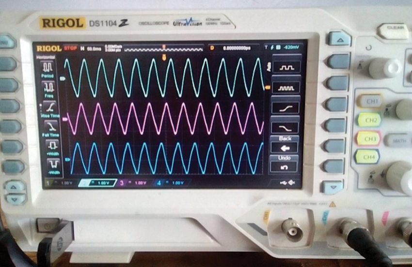
Figure 26: The 60 degrees phase shifted output voltages R R’ Y
In this work a novel three phases to six phase power conversion system is proposed and developed. The novelty of the system is that it uses a single phase AC link that provides a resonant high frequency AC link so that the power density of the system is improved. Any desired frequency on the load side could be achieved. The proposed system has generated the six phase AC output by employing the extended version of the Space Vector Modulation typically equivalent to that of a two, three phase systems with a phase shift of 60 degrees between the phases. The proposed idea has been validated using the relevant simulations in the MATLAB SIMULINK environment and an experimental verification unit. The proposed system is the power electronic equivalent to the conventional three phase to six phase system that uses two three phase transformers with STAR STAR and STAR DELTA configurations. Thus with the proposed idea, for the purpose of running a twelve pulse rectifier the use of two numbers of bulky transformers with STAR and STAR DELTA configurations could be avoided. The proposed solid state three phase to six phase converter can be used as the core converter for the shunt active power filter for the improvement of power quality in three phase systems. The increased number of phases in the core converter increases reliability, fault tolerant and it decreases the current stress through the semiconductors of the converter.
Many avenues are available for the future extension of the work. The proposed six phase power converter can be used the grid integration of renewable energy sources. The six phase converter scheme may be used to act as the core converter for a potential Active power filter. Torque ripple reduced low current six phase induction motors may be developed with variable voltage variable frequency drive schemes for industrial drives.
Acknowledgement: The authors would like to thank Anna University and also we like to thank Anonymous reviewers for their so-called insights.
Funding Statement: The authors received no specific funding for this study.
Conflicts of Interest: The authors declare that they have no conflicts of interest to report regarding the present study.
1. P. K. Sood and T. A. Lipo, “Power conversion distribution system using a high-frequency AC link,” IEEE Transactions on Industry Applications, vol. 24, no. 2, pp. 288–300, 1988. [Google Scholar]
2. F. C. Schwartz, “An improved method of resonant current pulse modulation for power converters,” IEEE Transactions on Industrial Electronics and Control Instrumentation, vol. IECI-23, no. 2, pp. 133–141, 1976. [Google Scholar]
3. R. L. Steigerwald, “High-frequency resonant transistor DC-DC converters,” IEEE Transactions on Industrial Electronics, vol. IE-31, no. 2, pp. 181–191, 1984. [Google Scholar]
4. I. D. Kim and G. H. Cho, “New bilateral zero voltage switching AC/AC converter high frequency partial-resonant link,” in Proc. IEEE Industrial Electronics Society, Pacific Grove, CA, USA, pp. 857–862, 1990. [Google Scholar]
5. M. Amirabadi, A. Balakrishnan, H. Toliyat and W. Alexander, “High frequency AC-link PV inverter,” IEEE Transactions on Industrial Electronics, vol. 61, no. 1, pp. 281–291, 2014. [Google Scholar]
6. A. Balakrishnan, M. Amirabadi, H. Toliyat and W. Alexander, “Soft switched ac-link wind power converter,” in Proc. ICSET, IEEE, Singapore, pp. 318–321, 2008. [Google Scholar]
7. A. Iqbal, M. Meraj, M. Tariq, K. A. Lodi, A. I. Maswood et al., “Experimental investigation and comparative evaluation of standard level shifted multi-carrier modulation schemes with a constraint GA based SHE techniques for a seven-level PUC inverter,” IEEE Access, vol. 7, pp. 100605–100617, 2019. [Google Scholar]
8. A. Routray, R. K. Singh and R. Mahanty, “Harmonic minimization in three-phase hybrid cascaded multilevel inverter using modified particle swarm optimization,” IEEE Transactions on Industrial Informatics, vol. 15, no. 8, pp. 4407–4417, 2019. [Google Scholar]
9. H. Azeem, S. Yellasiri, V. Jammala, B. S. Naik and A. K. Panda, “A fuzzy logic based switching methodology for a cascaded H-bridge multi-level inverter,” IEEE Transactions on Power Electronics, vol. 34, no. 10, pp. 9360–9364, 2019. [Google Scholar]
10. W. Peng, Q. Ni, X. Qiu and Y. Ye, “Seven-level inverter with self-balanced switched-capacitor and its cascaded extension,” IEEE Transactions on Power Electronics, vol. 34, no. 12, pp. 11889–11896, 2019. [Google Scholar]
11. C. Ramulu, P. Sanjeevikumar, R. Karampuri, S. Jain, A. H. Ertas et al., “A solar PV water pumping solution using a three-level cascaded inverter connected induction motor drive,” Engineering Science and Technology, an International Journal, vol. 19, no. 4, pp. 1731–1741, 2016. [Google Scholar]
12. P. G. I. Ngome, D. L. M. Nzongo, R. C. C. Flesch, J. S. Manguelle, M. Wang et al., “Model predictive current control based on a generalised adjacent voltage vectors approach for multilevel inverters,” IET Power Electronics, vol. 12, no. 13, pp. 3590– 3599, 2019. [Google Scholar]
13. T. S. Basu and S. Maiti, “A hybrid modular multilevel converter for solar power integration,” IEEE Transactions on Industry Applications, vol. 55, no. 5, pp. 5166–5177, 2019. [Google Scholar]
14. S. Selvaperumal, C. C. A. Rajan and S. Muralidharan, “Stability and performance investigation of a fuzzy-controlled LCL resonant converter in an RTOS environment,” IEEE Transactions on Power Electronics, vol. 28, no. 4, pp. 1817–1832, 2013. [Google Scholar]
15. S. Muralidharan and S. Menaka, “Application of evolutionary algorithms for harmonic profile optimization in symmetric multilevel inverter used in medical electronic equipments,” Current Signal Transduction Therapy, vol. 14, no. 1, pp. 12–20, 2019. [Google Scholar]
16. S. Menaka and S. Muralidharan, “Symmetric and asymmetric multilevel inverter topologies with device count: A review,” International Journal of Pure and Applied Mathematics, vol. 120, no. 6, pp. 10875–10904, 2018. [Google Scholar]
17. S. Muralidharan and C. C. A. Rajan, “Design, simulation and analysis of neural controller based series resonant converter,” in Proc ICMET, Singapore, pp. 144–147, 2010. [Google Scholar]
18. C. Vidhya, V. Ravikumar and S. Muralidharan, “Resonant BLDC motor drive system for medical applications,” Current Signal Transduction Therapy, vol. 16, no. 1, pp. 63–71, 2021. [Google Scholar]
 | This work is licensed under a Creative Commons Attribution 4.0 International License, which permits unrestricted use, distribution, and reproduction in any medium, provided the original work is properly cited. |