DOI:10.32604/iasc.2022.023890
| Intelligent Automation & Soft Computing DOI:10.32604/iasc.2022.023890 | |
| Article |
Integrated Renewable Smart Grid System Using Fuzzy Based Intelligent Controller
1Department of EEE, RMK College of Engineering and Technology, Chennai, 601206, India
2Department of EEE, Sona College of Technology, Salem, 636302, India
*Corresponding Author: V. Vijayal. Email: vijayalv2021@gmail.com
Received: 25 August 2021; Accepted: 02 November 2021
Abstract: In high power medium voltage applications, the utilization of 5-H Bridge Multi-Level Inverter (MLI) has grown vastly in recent years. The 5-H Bridge MLI can effectively control link voltage as well as power factor. However, the inverter imparts harmonics owing to the high switching frequency. Hence Inductance Capacitance Inductance (LCL) filter is implemented at its output to mitigate harmonics in presence of non-linear load. It’s of highly important to choose LCL parameters wisely in order to attain good filtering effect. This work investigates the application of 5-H Bridge MLI with LCL filter at the output for efficient integration of renewable energy sources on to the grid. A modified fuzzy heuristic approach is used to solve LCL power filter optimization problem at output of 5-H Bridge Multi-Level Inverter. Subject to the constraint’s harmonic distortion and losses of the inverter, multi objective optimization problem is solved to obtain LCL filter optimal values. The optimized LCL filter design was applied to a grid connected cascaded H-bridge MLI of rating 4.5 MW, 11 kV. MATLAB-Simulink is utilized for modelling and simulating the system. The results showed that the system is more efficient and generic. dSPACE Hardware in Loop (HIL) test system was used to verify the efficacy of the prototype system.
Keywords: 5-H bridge MLI; LCL filter; renewable energy; power quality; fuzzy heuristic algorithm; genetic algorithm
The world energy demand keeps increasing whereas the availability of conventional sources is on down trend. Apart from that, the increased carbon emissions from conventional energy sources results in greenhouse effect and global climate change. Thus, there is global shift towards renewable energy sources due to its wide abundance and zero carbon emissions. Solar PV and wind energy systems are the major contributors. The currently installed capacities of solar and wind energy are 580.1 and 622.7 GW out of 2563.8 GW total renewable energy capacity globally. Other than ever increasing global power demand, shift towards electric vehicles to reduce greenhouse effect plays a key role in increased deployment of solar and wind energy systems in future [1]. Electronic converters facilitate the interconnection renewable energy source on to the grid. The intermittent nature of renewable energy sources and the electronic converters brings harmonics and power quality issues to the system. In order to maintain the system stability, it is highly essential to maintain the system harmonics within a standard limit as mentioned in IEEE-519. This in turn mandates effective designing of output filter and inverter for optimal grid connection of renewable energy sources [2].
Multilevel inverters produce staircase type output which is nearly sinusoidal, and the output is better than a conventional two-step version. Multilevel inverter offers several merits over the two-level inverter such as it can produce high output voltage at lower switching frequency, low voltage stress, Minimum Electromagnetic Inference (EMI), low Total Harmonic Distortion (THD) and reduced filter size [3]. 5-H Bridge Multi-Level Inverter (5-H BMI) can handle real as well as reactive power control. With proper regulation of DC link voltage, it can supply energy to the grid. Hence Voltage source based Multi-level inverter can be applied for effective renewable energy integration to the grid in high power-medium voltage applications.
In order to choose the best filter topology for the given application, factors such as weight, efficiency and volume are considered. The first order topology i.e., L-filter is applied generally in high frequency switching applications. But it has low ability towards harmonic mitigation and bulk in size. The second order LC filter whose damping ability is quite comparable to that of L filter and hence better performance. Yet high inductance requirement in case of cut off frequency achievement, problem of resonance with grid impedance and possibility of capacitor exposure to harmonics from line voltage makes this topology unsuitable.
The third order LCL filter which doesn’t have any of the above stated issues associated with the other two topologies is preferred for high power medium voltage applications [4,5]. Power harmonics is the most serious problem in case of grid interconnection as they lead to heating, overloading, life reduction, insulator ageing and etc. Harmonics affect both the consumer and utility. Increased interconnection of non-linear loads and power electronic converters induces harmonics on to the system. Increased penetration of renewable energy increases power electronic converter deployment thus resulting on additional harmonic generation within the grid system.
Passive power filters (PPFs) possess advantages over active power filter (APFs) such as maintenance free, simple operation, low cost and simpler structure. Hence this work investigates design of PPF (LCL filter) at the end of 5-H BMI for optimal integration of renewable energy. Also, control strategy for controlling real power and reactive power output of the inverter is described. This relives power quality and instability issues in case of distributed systems [6,7]. In [8] genetic algorithm was used to optimize fuzzy controller in Un-interrupted power supply applications. 5-H Bridge Multi-Level Inverter with LCL filter was used [9] to regulate the grid current. Discusses the thermal effects and size consideration in LCL filter design for aerospace applications [10,11] presents optimal design techniques in LCL filter design.
Conventional PPF design methodologies with prerequisite of expertise in engineering and system details may not result in optimal results. Hence this work proposes a simple optimization model using improved fuzzy – genetic algorithm [12] approach to design LCL filter at the output of 5-H BMI for effective integration of renewable energy system on to the grid.
The basic system integrating renewable energy source PV system to the grid through 5-H Bridge Multi-Level Inverter with LCL filter at end is depicted in Fig. 1. The current work emphases on design and implementation of LCL filter at the end of 5-H BMI for harmonic mitigation and effective integration of renewable energy system on to the grid. Fuzzy heuristic approach is used in this filter system design.
The LCL filter attenuation rate is 60 dB/decade when the frequency is above resonant frequency, hence it can be operated satisfactorily with low switching frequency. The filter also features low current ripple for grid inductor and better decoupling from grid impedance. Hence LCL filter pertains to be the suitable choice for the renewable energy integration to the grid.
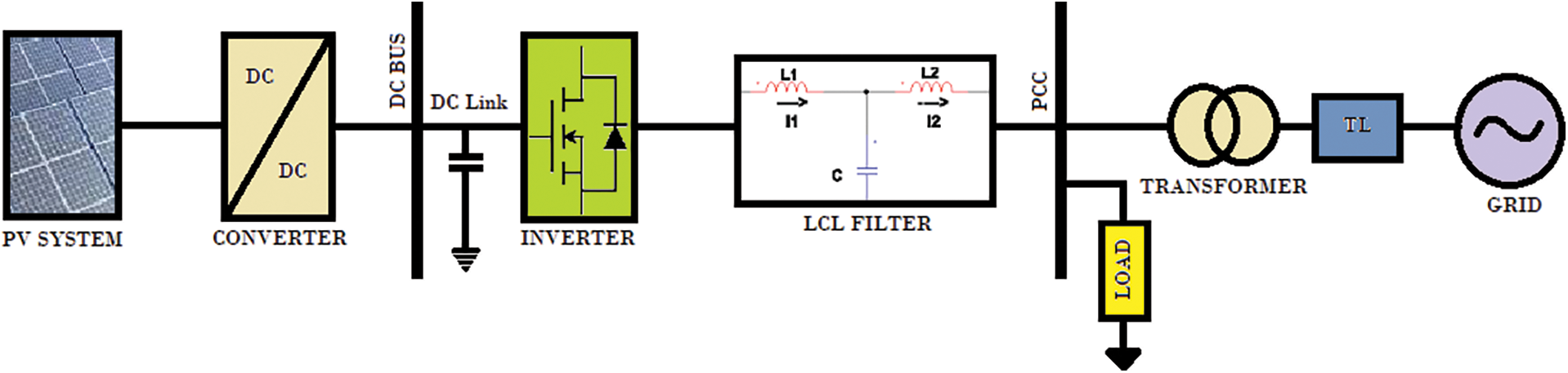
Figure 1: System integration
The filter can attenuate current ripples regardless of low inductance values but it can also bring unstable states and resonance to the system. Henceforth, the filter design must be specific to the application converter specification.
Numerous factors like switching ripple attenuation, size of filter and current ripple influence the designing of LCL filter. The line to line RMS voltage of inverter output (
where
Cut-off frequency of the filter is an important factor and it has to be chosen perfectly. The cut off frequency must be selected in such a way that the filter has enough capacity to attenuate in converter’s switching frequency range. On the other hand, there must be enough distance from grid frequency. The formula to calculate cut-off frequency of LCL filter is given below:
where
Active damping is followed to reduce the heat losses in the system. The circuit diagram and transfer function block diagram of LCL filter are depicted in Fig. 2.
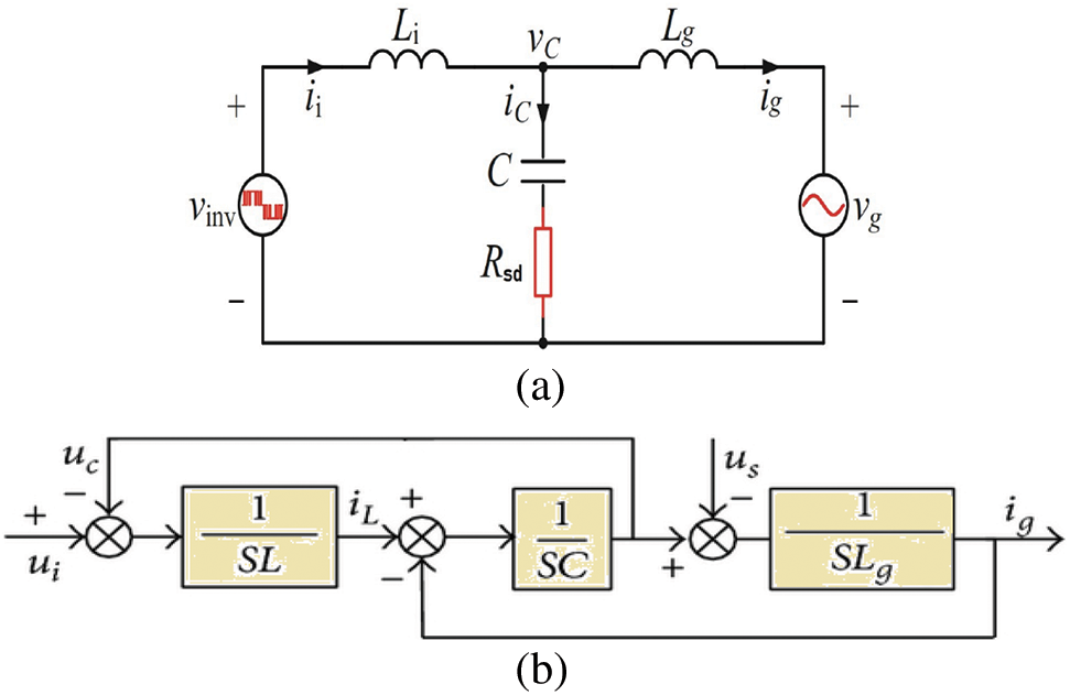
Figure 2: (a) LCL filter topology, (b) transfer function block diagram of LCL filter
The transfer function representing the LCL filter with damping resistor connected in series to the capacitor is depicted in Eq. (9).
4 Optimization Based LCL Design
The conventional way of LCL filter design requires engineering expertise and too many details of the system for design procedure and may not assure optimal solution. Hence in this work improved fuzzy-Genetic Algorithm based optimization approach was proposed to attain an optimal solution subject to the design constraints. A seven-level multilevel converter was taken for the study.
Objective 1: To minimize the total harmonic distortion of the output voltage
where
Objective 2: to minimize the cost of energy losses,
In case of multilevel inverters, the main losses are associated with the power switching devices. The types of losses can be classified as gate losses, conduction losses, off-state losses and switching losses. But in actual practice losses associated with gate and off-state are negligible. Therefore, only conduction and switching losses are considered here. And for filter design, total energy losses of each switch is calculated accurately. The losses that occur in a semiconductor device during its on-state is called as the conduction losses.
The conduction power associated with an IGBT switch can be directly obtained by multiplying on-state current and on-state voltage. The on-state voltage is a quadratic equation in terms of on-state current and depending on the device data sheet obtained separately for IGBT and the anti-parallel diode. Switching losses occurs in a semiconductor switch with power dissipation associated during turning on and off of the device. The switching loss is associated with switching frequency and substantially increases the inverter’s total losses with higher switching frequencies. The switching losses are further categorised into two effects, one is IGBT (i.e., losses that occur while turn on and turn off) and another one is anti-parallel diode (i.e., losses occur while turn on and turn off). But owing to the fast conduction in forward biased condition of anti-parallel diode, the losses associated with its turn on is normally neglected.
5 Functional Constraints of Optimization
Constraints should be added to the LCL filter design to guarantee good operation of power system. Hence several constraints like current and voltage distortion at the point of common coupling (PCC), size of filter capacitor, ripple current of inductor, size of filter inductance and filter’s resonant frequency are depicted as below:
5.1 Total Harmonic Distortion Limit
The voltage and current harmonic distortion limits are to be maintained as per the IEEE-1547 and IEEE-519 standards. IEEE-519 gives us the recommendations for voltage harmonic distortion at the PCC. For voltages up to 69 kV the THD must not exceed 5% with voltage distortion up to 3%. IEEE-1547 gives us the recommendations for current harmonic distortion up to voltage limit of 69 kV and harmonic order less than 11, the THD must be less than 5%.
Ripple current from inverter side inductance must be restricted below 30% of rated current. Hence high impedance values are utilized for LCL design. But high impedance in filter inductor will drop more voltage. Therefore, the filter’s total inductance is bounded to 0.15 p.u.
In order to limit power factor variation below 5%, the filter capacitance (
In order to avoid resonance with grid, the frequency of the filter has to be kept much greater than grid frequency. On the other hand, to enhance attenuation of harmonics generated by inverter, the resonant frequency has to be chosen at-least 50 percent less than inverter switching frequency. This is to avoid system destabilization and amplification of system harmonics.
Thus, the value of resonant frequency value is chosen in the range of 500 and 2500 Hz [13,14]. The optimized design values and the system parameters are represented in Tab. 1.

5.5 Improved Fuzzy-GA Optimization Based LCL Filter Design
Fuzzy controller is used along with genetic algorithm optimization in LCL filter design. In genetic algorithm-based optimization during evolution the fuzzy logic controller is applied to optimize the bounding intervals in order to attain optimum result in the following step. The Fig. 3 depicts the improved fuzzy-GA optimization flowchart and Fig. 4 represents self-tuning fuzzy controller [15,16].
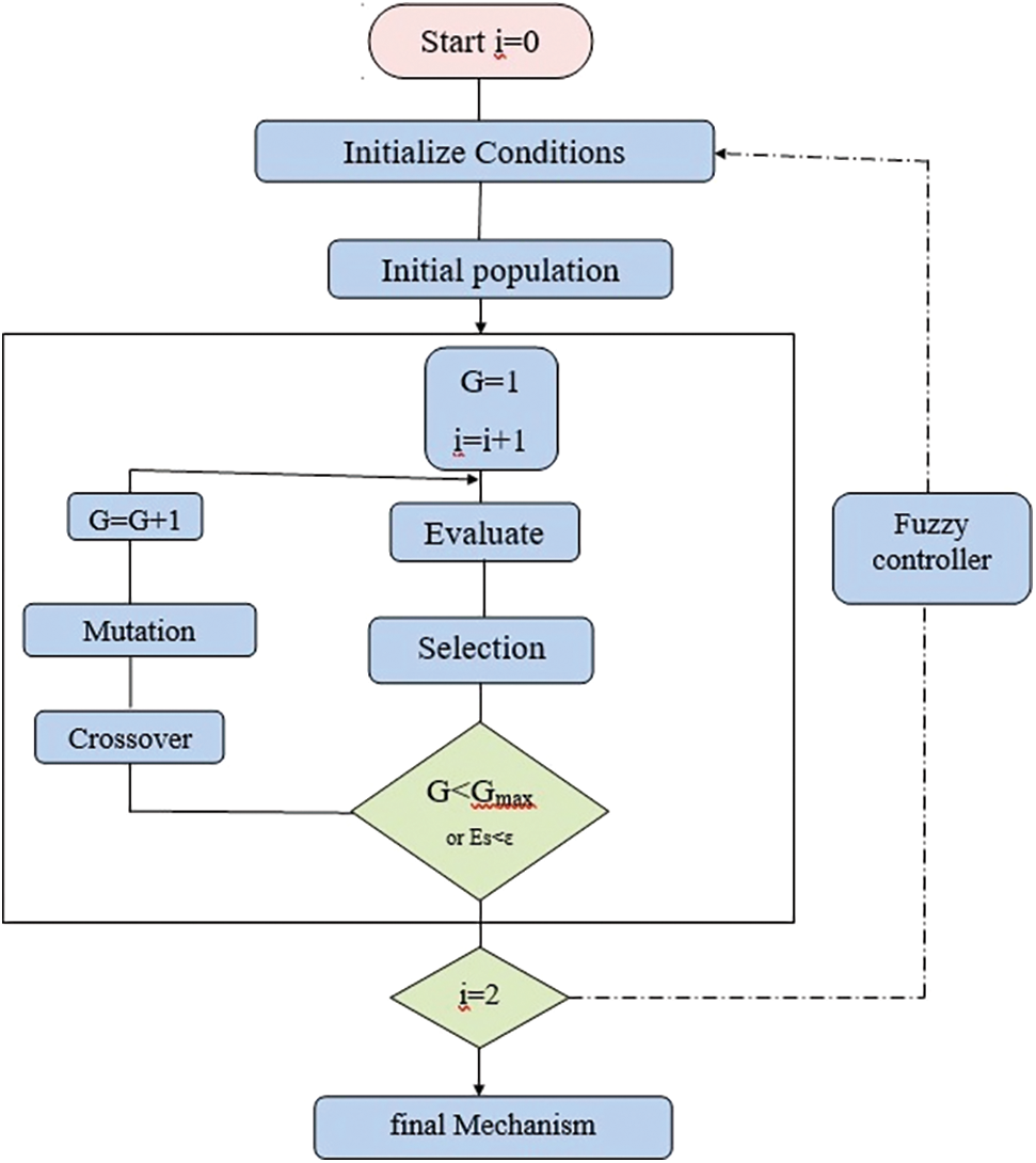
Figure 3: Improved fuzzy-GA optimization
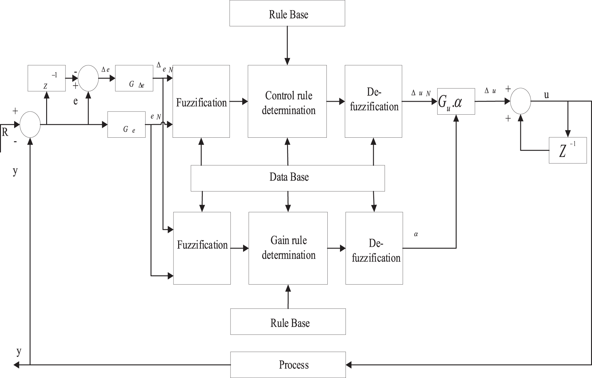
Figure 4: Fuzzy logic controller
Given the initial population and boundary condition, general genetic algorithm process [17] gets started. During the evolution every variable is monitored and the boundary levels [18,19] are modified by the fuzzy controller for each variable. The new bounding interval was then utilized to improvise the end result by repeating the optimization. New random population is initialized based on the new bound. During the genetic algorithm first run knowledge base is constructed. Correction factor
where

Figure 5: Flow chart for optimization process
The parameters of GA optimization are given in Tab. 2. The Fig. 6 represents the performance of GA in design optimization of LCL filter. The error, change in error and output fuzzy membership functions utilized in this work are represented in Fig. 7.

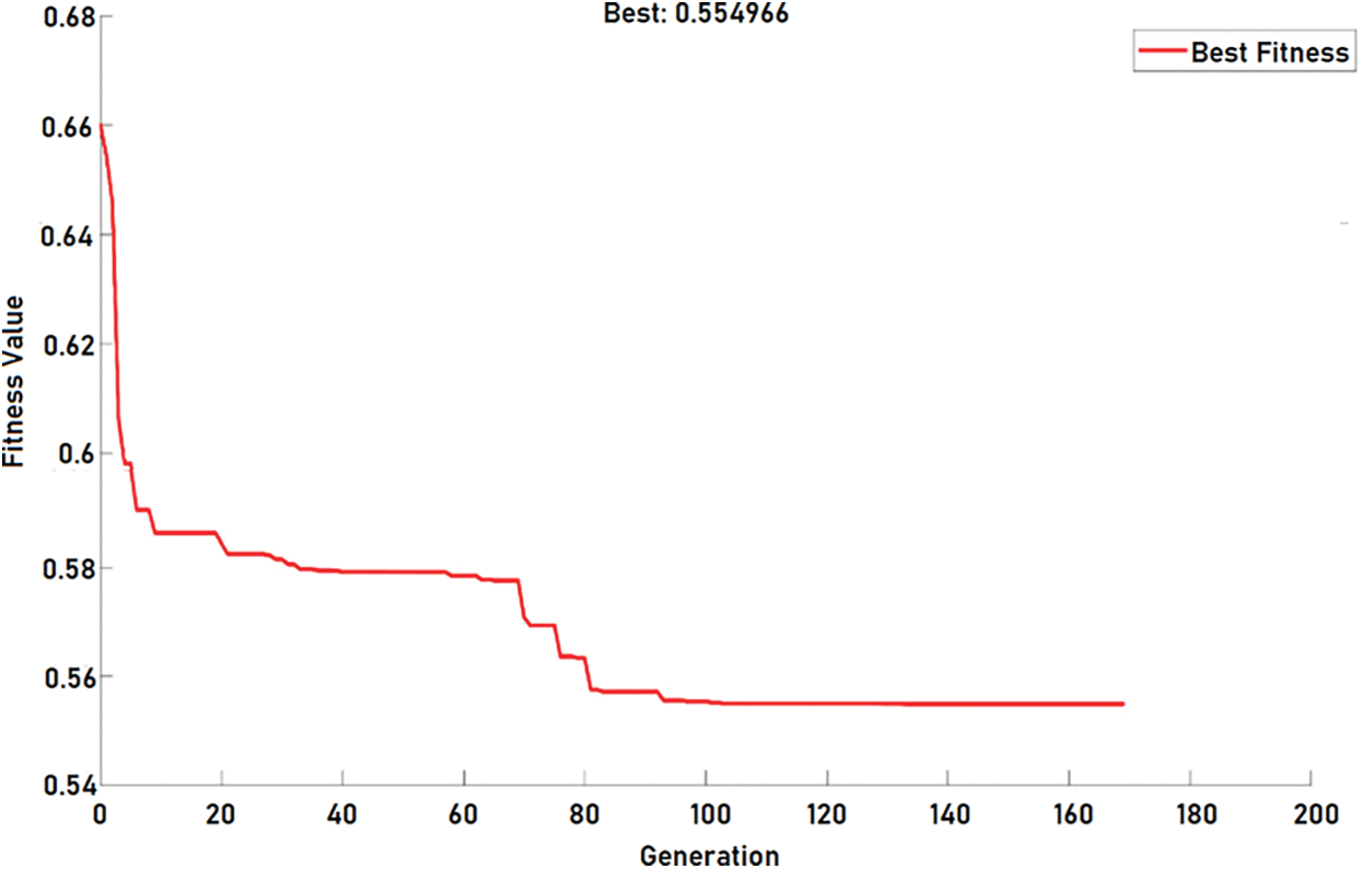
Figure 6: GA optimization

Figure 7: Fuzzy membership functions for (a) error, (b) change in error and (c) output

This fuzzy logic controller is more effective due to self-tunning capability which delivers fast response. It consists of a couple of input and an output. The set of 49 rules used in the fuzzy system is presented in Tab. 3. It has seven fuzzy sets (NB, NC, NM, ZE, PM, PC, PB) for both input and output membership functions. Due to simplicity, this controller implements the triangular membership function and also implements centroid method for defuzzification. Where NB is Negative Bulky, NC is Negative Central, NM is Negative Minor, ZE is Zero, PM is Positive Minor, PC is Positive Central and PB is Positive Bulky.
The simulation of the system is done in MATLAB Simulink. Phase- Disposition based Sinusoidal Pulse Width Modulation is used to control the inverter. Fuzzy- GA based optimization was applied for LCL filter design in order to integrate renewable energy optimally. The objective function is optimized to ensure reduction of power losses and THD. The optimized LCL filter integration at the output of the inverter has improved the output phase and line voltage outputs. The Figs. 8 and 9 represents the output phase voltage and line voltage before filter implementation. It is evident from the figure that there is so much of distortion in the output. The Figs. 10 and 11 represent the output phase and line voltage after filter implementation. After filter implementation it is observed that the harmonics are reduced to a greater extent and is sinusoidal. The Figs. 12 and 13 depict the total harmonic distortion in the output voltage before and after implementation of LCL filter. The harmonic distortion of the output voltage was reduced greatly from 6.49 % to 1.94 %. Once the optimized LCL filter was introduced the individual harmonics of the output voltage was reduced below 1% apart from the 3rd harmonics which was under 2%. The reduction in the harmonic level is due to the elimination of triplen harmonics. The performance of the designed filter in series connection at high frequencies is superior over the performance of damping resistor less LCL filter. Yet, the performance of both cases tends to be almost the same at low frequencies. Proper selection of series damping at resonant frequency results in enhanced peak suppression. The transfer function of the optimized LCL filter with damping resistor is given by Eq. (20). Fig. 14 gives bode plot diagram of the system with and without damping resistor. It is noted from the bode plot that before implementing the filter the gain margin is zero (i.e., there is no cross over frequency) and hence the system is marginally stable. But after implementing the filter the gain margin is positive and is about 13 dB. Similarly, the phase margin is also positive. Positive gain margin and phase margin implies that the system under consideration is stable.
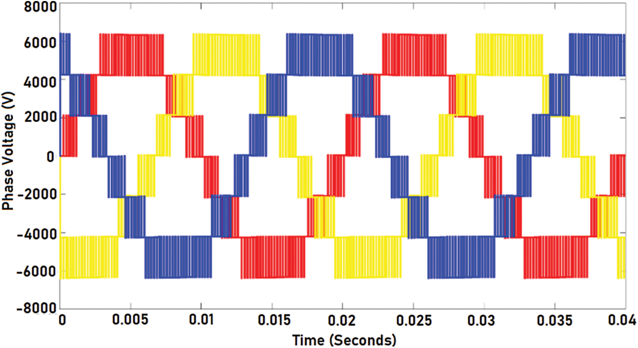
Figure 8: Three phase output voltage before filter implementation (line-ground)
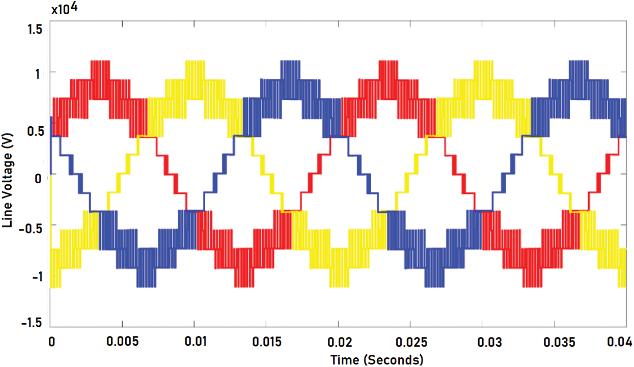
Figure 9: Three phase output voltage before filter implementation (line-line)
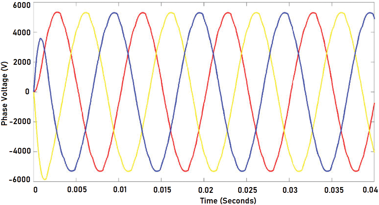
Figure 10: Output phase voltage after implementing optimized LCL filter
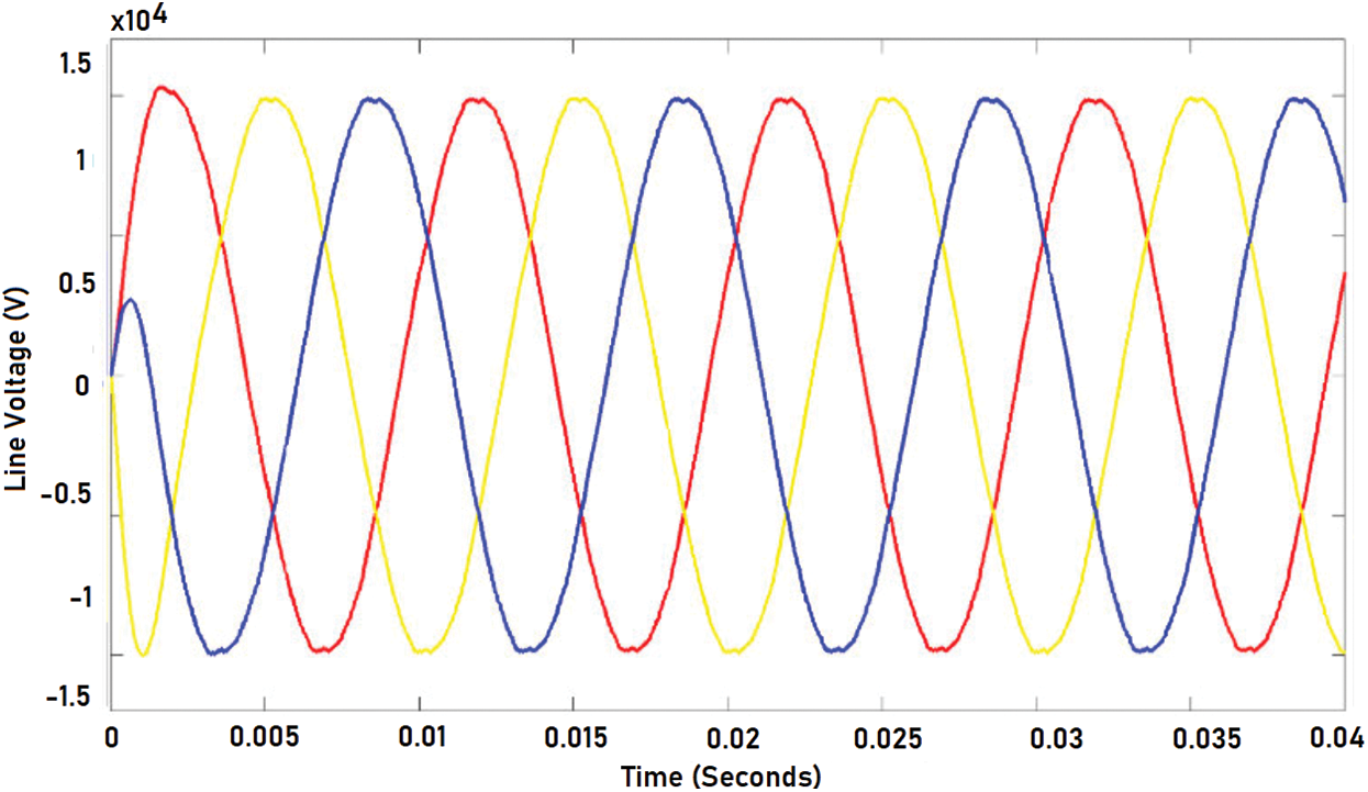
Figure 11: Output phase voltage after implementing optimized LCL filter
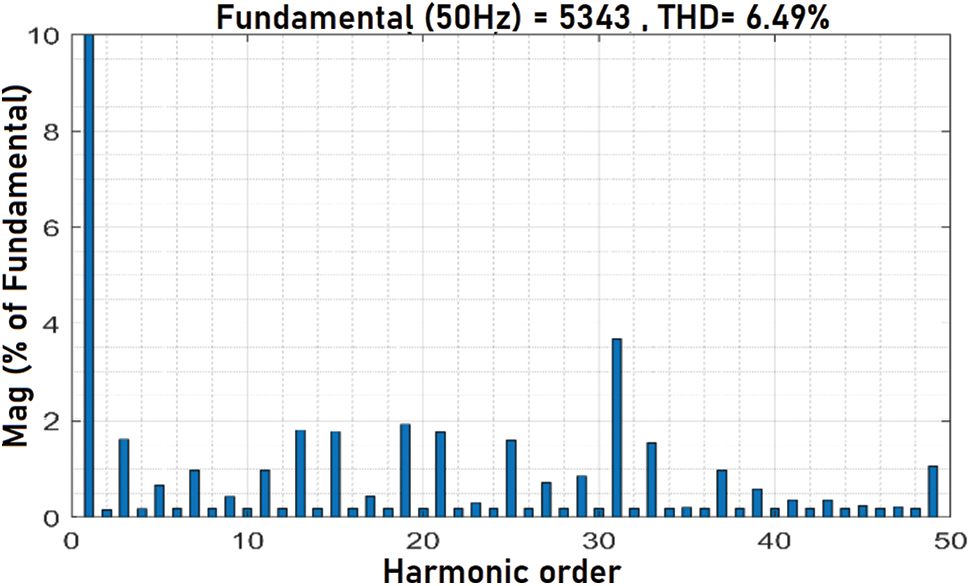
Figure 12: THD of the system before LCL filter integration
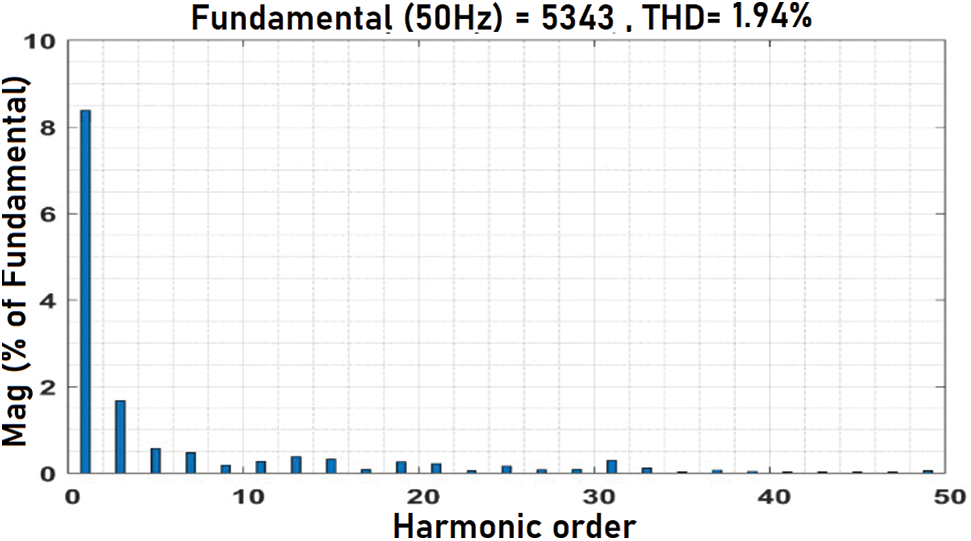
Figure 13: THD of the system after optimized LCL filter integration
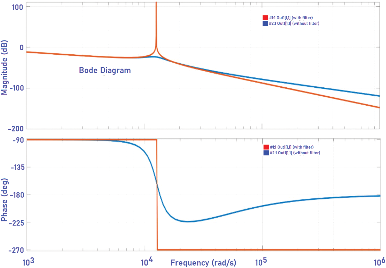
Figure 14: Bode plot of the system with and without damping resistor
The total harmonic distortion capability of the Fuzzy-GA optimized LCL filter is compared to that of LCL filter design in as shown in below Tab. 4. The results show that the THD capability of the optimized filter is far better than of the improvised LCL filter.

dSPACE hardware-in-the-loop based prototyping is used to realize the 5-H Bridge Multi-Level Inverter [20–22] system with optimized filter which allows us to have better comparison between simulation and hardware results. The modules in the setup include a dSPACE 1104 type real-time hardware, relay circuits, PV Emulator, Semikron inverter, voltage and current sensor for feedback purpose, LCL filter and a PC which consists of control software which has the capability to run MATLAB simulation of the given system. A three-phase diode bridge rectifier with a DC load of 300 W is used in order to test the performance of the system with non-linear load.
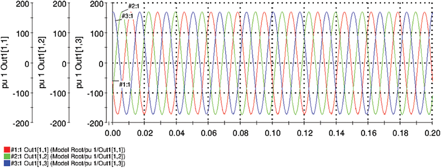
Figure 15: Phase voltage measured at load end

Figure 16: Line current measured at load end
Figs. 15 and 16 shows the output phase voltage and line current measured at load end points respectively. From these figures, it is evident that the output voltage and current are almost virtuously sinusoidal. The direct axis component
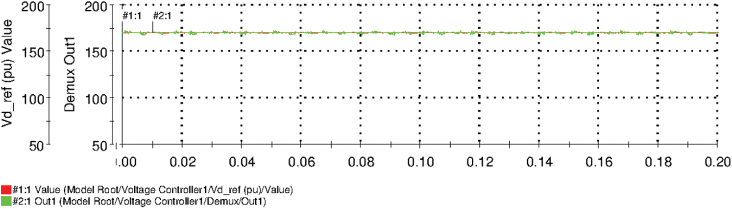
Figure 17: Direct axis component
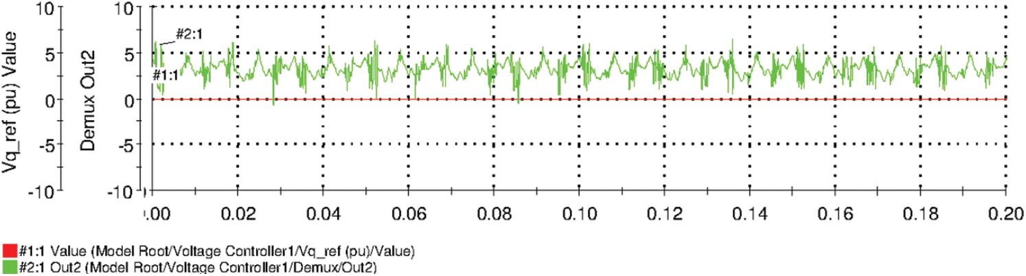
Figure 18: Quadrature axis component
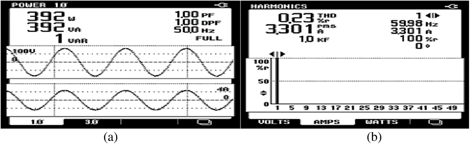
Figure 19: (a) Phase power signal and (b) THD

In order to supply the fast-mounting global power demand, renewable energy integration on to grid is increasing hastily. Solar PV and wind turbine farms highly expected to dictate the future smart grid. Integration of renewable energy technologies on to the grid is through power electronic controllers such as rectifier and inverter which tend to impose harmonics on the system. This affects the quality of power at both consumer and utility side. There are numerous solutions widely available in the literature but the passive filters remain the most economical and are extensively utilized in industrial applications. LCL passive filter optimization results in effective integration of renewable energy sources on to the grid and also ensures harmonic levels well below recommended standards. This work is targeted to deliver an optimized yet generic design of LCL filter at the output of 5-H Bridge Multi-Level Inverter in-spite of the constraints. THD and power losses are minimized appropriately using a multi-objective function-based error minimization technique. The optimization thus formed resulted in an effective reduction of harmonics and power losses in the system. The output power quality of the system under consideration was improved significantly. The same was verified using a laboratory prototype using a dSPACE HIL system.
Acknowledgement: The authors would like to thank Anna University and also we like to thank Anonymous reviewers for their so-called insights.
Funding Statement: The authors received no specific funding for this study.
Conflicts of Interest: The authors declare that they have no conflicts of interest to report regarding the present study.
1. J. Almaguer, V. Cardenas, A. A. Torres, M. Gonzalez and J. Alcala, “A frequency-based LCL filter design and control considerations for three-phase converters for solid-state transformer applications,” Electrical Engineering, vol. 101, no. 2, pp. 545–558, 2019. [Google Scholar]
2. G. Majic, M. Despalatovic and B. Terzic, “LCL filter design method for grid-connected PWM-VSC,” Journal of Electrical Engineering and Technology, vol. 12, no. 5, pp. 1945–1954, 2017. [Google Scholar]
3. J. Jo and H. Cha, “Design of effective passive damping resistor of grid-connected inverter with LCL filter for industrial applications,” Journal of Electrical Engineering & Technology, vol. 14, no. 5, pp. 2039–2048, 2019. [Google Scholar]
4. S. Eren, M. Pahlevaninezhad, A. Bakhshai and P. K. Jain, “Composite nonlinear feedback control and stability analysis of a grid-connected voltage source inverter with LCL filter,” IEEE Transactions on Industrial Electronics, vol. 60, no. 11, pp. 5059–5074, 2013. [Google Scholar]
5. D. Solatialkaran, F. Zare, T. K. Saha and R. Sharma, “A novel approach in filter design for grid-connected inverters used in renewable energy systems,” IEEE Transactions on Sustainable Energy, vol. 11, no. 1, pp. 154–164, 2020. [Google Scholar]
6. X. Renzhong, X. Lie, Z. Junjun and D. Jie, “Design and research on the LCL filter in three-phase PV grid-connected inverters,” International Journal of Computer and Electrical Engineering, vol. 5, no. 3, pp. 322, 2013. [Google Scholar]
7. R. P. Alzola, M. Liserre, F. Blaabjerg, M. Ordonez and Y. Yang, “LCL-filter design for robust active damping in grid-connected converters,” IEEE Transactions on Industrial Informatics, vol. 10, no. 4, pp. 2192–2203, 2014. [Google Scholar]
8. B. Alamri and Y. M. Alharbi, “A framework for optimum determination of LCL-filter parameters for N-level voltage source inverters using heuristic approach,” IEEE Access, vol. 8, pp. 209212–209223, 2020. [Google Scholar]
9. W. Ding, L. Ming, C. Yin, P. Chiang, B. Duan et al., “An integrated common-mode fast-balancing mechanism for three-phase three-level converter with LCL filter,” IEEE Transactions on Power Electronics, vol. 36, no. 11, pp. 12694–12709, 2021. [Google Scholar]
10. C. G. Corral, J. Segundo, M. Esparza and R. Cruz, “Optimal LCL-filter design method for grid-connected renewable energy sources,” International Journal of Electrical Power & Energy Systems, vol. 120, no. 5, pp. 105998, 2020. [Google Scholar]
11. Y. J. Kim and H. Kim, “Optimal design of LCL filter in grid-connected inverters,” IET Power Electronics, vol. 12, no. 7, pp. 1774–1782, 2019. [Google Scholar]
12. S. M. Odeh, A. M. Mora, M. N. Moreno and J. J. Merelo, “A hybrid fuzzy genetic algorithm for an adaptive traffic signal system,” Advances in Fuzzy Systems, vol. 2015, no. 3, pp. 1–11, 2015. [Google Scholar]
13. N. Rasekh and M. Hosseinpour, “LCL filter design and robust converter side current feedback control for grid-connected proton exchange membrane fuel cell system,” International Journal of Hydrogen Energy, vol. 45, no. 23, pp. 13055–13067, 2020. [Google Scholar]
14. G. E. M. Ruiz, N. Munoz and J. B. Cano, “Modeling, analysis and design procedure of LCL filter for grid connected converters,” in Proc. Power Electronics and Power Quality Applications, Bogota, Colombia, IEEE, pp. 1–6, 2015. [Google Scholar]
15. J. Chen, “Adaptive fuzzy neural network control based on genetic algorithm,” in Proc. Int. Conf. on Measuring Technology and Mechatronics Automation, Beihai, China, IEEE, pp. 393–396, 2021. [Google Scholar]
16. K. Aishwarya and P. D. Dewangan, “Design of fuzzy-PID controller for a genetic algorithm based reduced order model,” in Proc. Int. Conf. for Emerging Technology, Belagavi, India, IEEE, pp. 1–6, 2021. [Google Scholar]
17. L. Zhou, Z. Liu, Y. Ji, D. Ma, J. Wang et al., “An improved parameter design method of LCL APF interface filter,” in Proc. Int. Conf. on Artificial Intelligence and Computer Applications, Dalian, China, IEEE, pp. 948–952, 2020. [Google Scholar]
18. C. Nagarajan and M. Madheswaran, “Stability analysis of series parallel resonant converter with fuzzy logic controller using state space techniques,” Electric Power Components and Systems, vol. 39, no. 8, pp. 780–793, 2011. [Google Scholar]
19. C. Nagarajan and M. Madheswaran, “DSP based fuzzy controller for series parallel resonant converter,” Frontiers of Electrical and Electronic Engineering, vol. 7, no. 4, pp. 438–446, 2012. [Google Scholar]
20. C. Nagarajan and M. Madheswaran, “Experimental study and steady state stability analysis of CLL-T series parallel resonant converter with fuzzy controller using state space analysis,” Iranian Journal of Electrical & Electronic Engineering, vol. 8, no. 3, pp. 259–267, 2012. [Google Scholar]
21. C. Nagarajan and R. Prakash, “A digital signal processor based capacitor inductor inductor resonant converter for stand alone wind energy system using AC analysis,” International Journal of Engineering, Science and Technology, vol. 12, no. 4, pp. 54–62, 2021. [Google Scholar]
22. A. Appathurai, R. Sundarasekar, C. Raja, E. J. Alex, C. A. Palagan et al., “An efficient optimal neural network-based moving vehicle detection in traffic video surveillance system,” Circuits, Systems, and Signal Processing, vol. 39, no. 2, pp. 734–756, 2020. [Google Scholar]
 | This work is licensed under a Creative Commons Attribution 4.0 International License, which permits unrestricted use, distribution, and reproduction in any medium, provided the original work is properly cited. |