DOI:10.32604/iasc.2022.022979
| Intelligent Automation & Soft Computing DOI:10.32604/iasc.2022.022979 | |
| Article |
Incredible VLSI Design for MIMO System Using SEC-QPSK Detection
Department of ECE, Tejaa Shakthi Institute of Technology for Women, Coimbatore, Tamil Nadu, 641659, India
*Corresponding Author: L. Vasanth. Email: vasanthpaper@gmail.com
Received: 24 August 2021; Accepted: 21 October 2021
Abstract: Multiple Input Multiple Output (MIMO) is an advanced communication technology that is often used for secure data transfer for military and other applications while transmitting data with high error and noise. To address this issue, a step-by-step hybrid Quadrature Phase Shift Keying (QPSK) modulation scheme in the MIMO system for a complex Very Large-Scale Integration (VLSI) format is recommended. When compared to Binary Phase Shift Keying (BPSK), this approach provides twice the data rate while using half the bandwidth. The complexity is lowered through multiplication and addition, as well as error and noise reduction in data transport, and MIMO detection is accomplished through the combination of two techniques, Inverse Fast Fourier Transform (IFFT) and Stepwise Exponential Companding (SEC). IFFT converts frequency to the time domain, reducing complexity by 23.56 percent in multiplication and an extra 34.05 percent. Likewise, hierarchical high-speed mixing decreases difficult limits by 13% and the addition problem by 25%. This technological outcome results in a decreased Signal-to-Noise Ratio (SNR) and Bit Error Rate (BER).
Keywords: MIMO (multi-input multi output); QPSK (quadrature phase shift key); IFFT (inverse fast fourier transform); SEC (stepwise exponential companding)
Mobile transmission is an important component of everyone’s daily life in terms of communication. Data is delivered to a long distance in wireless communication [1]. Without any cable or fiber, the data is delivered between the sender and receiver [2]. Many applications rely on the wireless connection at the moment. WIFI and WLAN are two examples of widely used wireless technologies. QPSK modulation based on SEC and IFFT techniques is introduced to boost efficiency and throughput [3]. MIMO is a cutting-edge technique that is widely employed in mobile transmission as well as sends data securely [4]. It’s strategies can be divided to two categories: hard spotting and soft spotting. The basic understanding of hard-spotting is to make direct contact with the potential set for the index vector [5], which is coupled to the communication signal vector and then output the spotting effect. The receiver in the MIMO approach should be aware of the channel’s characteristics. Their knowledge of the channel can be obtained based on the matrix value [6].
The main problems in realizing the promise of MIMO systems [7] are to build detection algorithms with high throughput and low complexity while obtaining near-optimal performance, as seen in Fig. 1. In this thesis, a new strategy for reducing difficulty and obtaining a high throughput output signal is implemented [8]. Although PROM chips and FPGA are similar, FPGA offers more benefits compared to PROM (programmable read-only memory [9].

Figure 1: MIMO structure
The single input single output strategy has poor performance, which is solved by utilizing a MIMO technique. MIMO is an acronym that stands for multiple input multiple outputs, which means that one or more antennas assist at both the transmitter and reception ends [10]. Multiplexing or diversity inhibits spatial degrees of freedom in MIMO systems. Diversity refers to several copies of the same signal, often known as redundant information. For example, one or more antennas utilized at the communication system’s destination receive identical copies of signals [11]. However, the incoming data is wrecked due to uncorrelation and the existence of noise, therefore the two signals are blended to recover the original data with higher quality [12]. The similarity between this technique and others is that greater noise-reduced information was obtained by evaluating both identical signals from several communication receivers. The Space-Time Coding (STC) technique is one method for providing diversity at the source side by using numerous antennas [13].
Spatial multiplexing is another MIMO technique for improving performance. It is capable of sending data with less bandwidth and electricity. The number of transmitter and receiver antennas utilized in the spatial multiplexing technique can improve the throughput of any system exponentially [14]. The various combinations of data streams are transmitted by the transmitter antenna, and these bits are received as a linear function of data by the destination antennas [15]. When the presence of scattering is high enough to decode the number of signals received from distinct types of sending antennas, the matrix function of a wireless channel is reversed [16]. The gain of multiplexing is improved as a result of the MIMO system’s operation. MIMO systems always maintain a balance between multiplexing gain and diversity. The MIMO transceiver can discover an operating point in the region of gain of multiplexing and diversity based on wireless channel characteristics [17].
In a study titled Fully-Pipelined K-Best MIMO Detector with Successive Interference Cancellation, Bello et al. [18] examined a new VLSI detection algorithm. This paper reports a finest inverter though VLSI employment of an entirely tube-based inverter using 65-nm CMOS technology. The hybrid K-optimized method combines continuous noise suppression detection at minor class of search trees to reduce the problem of detecting low-level interference, with a target BER of 1033 and a 0.3-dB SNR loss. The enforcement results show that hybrid detection reduces area and power consumption by about 16% and 38%, respectively, when related to an entirely searched K-Best detector. Despite its 137 MHz clock frequency, the detector offers more than 3 Gbps performance, is compatible with wireless standards with reduced latency, such as IEEE 802.11ac.
Wu et al. [19] study avoids using the matrix’s reverse function, which reduces the size of the complex. Meanwhile, an optimal relaxation value has been suggested to further accelerate the proposed algorithm’s accumulation speed, and 2 approaches for computing record-probability ratios (LLRs) have been obtained. It has been demonstrated that the proposed approach for analysis and simulation outperforms other low-complexity signal identification procedures. The proposed method integrates fast and reaches its effectiveness only with a minimal number of MMSE algorithm performances.
Cai et al. [20], investigated A Low Complexity and High Throughput MIMO Detection VLSI Design for MIMO-OFDM Systems. The Linear Minimum Average Squared Error (MMSE) MIMO Detector Design for MIMO-OFDM Systems Based on Application-Specific Tool-Package Processor is finding of the present study (ASIP). The proposed MIMO detector, as part of the IEEE 802.11ac-compatible PHY baseband transceiver, provides less latency, great performance, and material consumption. The concept incorporates DSMC 40 Nm CMOS technology, with each QRT engine having about 245 K logic gates. It has a bandwidth of 20/40/80 MHz and 4 local streams. In 80 MHz VHD mode (234 data subcarriers), the detection delay is 750 Ns.
Kosasih et al. and colleagues [21] investigated Low Complexity Multi-User MIMO Detection for Uplink SCMA System Using Expectation Propagation Algorithm. In this paper, they introduced the Expectation Propagation System (EPA) for SCMA, a less difficult detection technique. Importantly, EPA-SCMA resolves the complicated challenge of MPA-SCMA and allows SCMA to be implemented in large MU-MIMO systems. When transmitting and receiving antennas are amplified, EPA can reach ideal detection performance, and a rotating design in the SCMA codebook has also been shown unnecessarily.
Yang and colleagues [22] investigated Massive MIMO Detection VLSI Design. The given solution reduces difficulty of MPD and enhances clear output. The belief propagation (BP) is intended to increase output. The proposed MPD achieves 6.9× better throughput while using 49% less energy than the prior art design. By using the same amount of energy, the present polar decoders produce a 1.35× increased throughput.
Adeva et al. [23], investigated VLSI Architecture for MIMO. The key strategies for constructing the first efficient operation of the SISO-TSD algorithm are provided in this article. A new representation was employed, which greatly decreases the difficulty when compared to advanced operations that require more than 10 bits. The legislative and architectural principles given enable the appropriate use of pipe and connecting systems. The costs of processing source data are also considered. Implementation of high performance, low-hardware-complexity, and low-power consumption are done in tandem with the definition of appropriate configuration. The final implementation demonstrates the best restoration receiver configuration.
The pie chart in Fig. 2 provides a summary of this paper’s methodology. The data is gathered and processed in a serial to parallel converter. For the next step, the output of the S/P converter is modulated with QPSK. IFFT is used to convert the time domain to frequency domain in order to acquire correct modulation values. SEC is used at the receiver end to recover the original signal.

Figure 2: Major steps involved in the proposed method
QPSK is important transition schemes in digital communication and the modulated waveform of the QPSK signal is shown in Fig. 3.

Figure 3: Wave form
3.1 Quadrature Phase Shift Keying (QPSK)
QPSK changes carrier signal to bits or symbols Consequently, the bandwidth required can only be half of the actual range. In this approach, a phase shift between the four carrier phase shifts is chosen (
This system is built with two carriers: an in-phase (I) carrier and a quadrature-phase (Q) carrier. The phase range of the odd carrier will vary from 0 degrees to 180 degrees and °, while the phase range of the even carrier will shift from 90 degrees to 270 degrees. This is how a two-bit binary code’s four potential states are represented. Two bits are represented by four separate carriers based on their odd or even capacities in this modulation. Each possible carrier in the modulation is given a symbol. These symbols are placed in a circle in a constellation diagram. QPSK delivers double the data rate while requiring half the bandwidth when compared to BPSK.
When a signal is sent from sender to receiver, channel state information is required to understand the channel properties, such as scattering, reflecting, multipath propagation, power decay, near far problem, noise, and error estimation in a noisy channel. This method is known as channel estimation, and it can be supported in a variety of ways.
• A parametric model
• Temporal relationship on a mobile channel.
• Flexible or non-flexible techniques are used.
In Time Division Multiple Access, for user’s full bandwidth is allocated at different times. The original signal is protected by coding in the OFDM system. At the start of each OFDM signal, there is a guard interval. The receiver can readily collect the signal if the echoes occur inside the guard period, but this is not possible if they occur outside of the guard interval. The OFDM system employs a guard interval of 0.8 s. A 0.4 s guard period is introduced to the OFDM system to boost the data flow. This result has a result of 18% in the data rate. Packet rate is considerable when guard interval is short. When data is transferred too long an impact is happened in mobile system’s performance.
3.2.1 SEC (Step Wise Exponential Companding)
SEC aims to integrate the benefits of both EC and PC systems. This innovative technique is used in an OFDM system to reduce the power value. Because the EC’s primary role is to diminish the input symbol’s power by uniformly spreading its amplitude, it lessens the power by changing its insight. EC offers few advantages, including the ability to maintain a constant average power level inside the nonlinear Companding operation. We can obtain several types of power level lowering approaches by selecting the suitable Pi and t values.
The OFDM signal transmission is shown in Fig. 4.

Figure 4: OFDM signal transmission
3.2.2 Phases for Performing SEC in MIMO System
Phase 1: Database source: This is encoded on the Transmitter side to obtain the necessary format. Overall, it is capable of producing messages as words, bytes, code, symbols, bits, sound signals, photos, and videos. The source’s primary function is to generate desired information that must be communicated. A symbol or data bit is the term used to describe the information in communication.
2nd Phase: Serial to parallel converter: Parallel transmission is utilized to avoid this type of problem. The fundamental advantage of a serial to parallel converter is that numerous data streams can be delivered simultaneously in various channels. As a result, parallel transmission is faster than serial transmission. Two shift registers are used to achieve this operation.
Phase 3: Modulation with QPSK: The S/P converter gives the data to the QPSK modulator. This modulates the signal with four phases. As an example, let us consider the QPSK signal with Tsym,
The carrier signal is modulated in each data stream. In BPSK, a single carrier modulates only one bit. Two bits are changed to single bit in QPSK method.
We can readily see from Eq. (2) that QPSK sends twice as much data as BPSK. The signal is multiplied by cos(2f c t), and the quadrature signal is multiplied by −sin(2f c t). By combining in-phase and quadrature-phase signals, the original QPSK signals are obtained. This is shown in Eq. (3)
fc -> carrier frequency
fs -> sampling frequency
Fig. 5 depicts the modulation of digital data transmission.

Figure 5: QPSK modulation
Phase 4: Pilot framing: Based on pilot criteria Pilot sequence generation is done. Let us consider pilot arrangements yi, i = 1, 2, …, M. Pilot sequences can help in both multi-cell and single-cell situations. The creation of multicell sequences is based on (CAZAC). Among these pilot sequences, chu sequences played an important role in generating correlation parameters for transmitting pilot signals. Let y1m Xlk be the pilot sequence spread by the mth user at the 1th cell, then y1m = [x] 0 k,…, [x] n k,…, [x] ρ − 1 k where ρ is the length of pilot sequences. As a result, it is widely known that extending the pilot sequence would increase channel accuracy, but the number of data to be communicated is relatively low because it will take more bandwidth. When the training period exceeds (Ns/2), the total rate is greatly condensed, and assume (Ns N smooth/2) Furthermore, the length of pilot sequences should not be smaller than K to assure orthogonality.
Phase 5: Perform an Inverted Fast Fourier transform (IFFT): It is a quick procedure to find DFT and IDFT values. IFFT has the complexity of N/2 log2 N. Frequency signals are changed to time domain signals using this method. Time domain refers to data relation to time.
Eq. (4) is used to find time domain signal representation.
The change of frequency domain to time domain is shown in Figs. 6a and 6b.

Figure 6: (a) Time-domain, (b) frequency domain
Frequency,
The period of a wave,
f = 1/T and T = 1/f are inversely relative to each other.
Phase 6: Channel: Where signals can travel. There must be one feasible solution, which is CSI, to generate the optimal channel or to know the optimum path correction. If several transmitters and reception antennas are arranged, it is possible to accomplish coherent recognition and diversity combining in OFDM. The signal is broadcasted over the channel. Channel estimate can be made significantly by a lack of understanding of channel data. To achieve flawless communication in the OFDM scheme, adequate channel selection is required.
Phase 7: DE-SEC is given by,
Sign function is denoted as sgn(*).
We need parameter Pc to determine SEC function. Parameter Pi is expressed in Eq. (7)
After de-companding function Pc and Pi are formed. Low power results are obtained by adjusting Pc, Pi, t.
Phase 8: BOQRM MLD: For detecting MMO signal, consider the below 4 × 4 matrix of MMO,
where, m1, m2, m3 The many transmit antennas, n1, n2, n3…, and Z11, z22, z33…, are the medium responses from the ith broadcasting antenna to the jth receiving antenna, respectively. The short form of Eq. (10), is expressed, m = Zl + n.
In full MLD technique 4 × 4 MIMO system, the replicate of a signal is calculated as follows,
In this method, both the transmitter and the receiver have perfect channel knowledge. Hence it is replaced by a product of Qd and Td, finally, the expression is expressed as, m = QdTdl + n
where
where tij denotes the component of Qd in the row j and column i.
[1] Step: The replica
From Eq. (14), (m3, m4) are calculated by graded in climbing order by the sum of the replica of the matrices (
where, Re (⋅) -> Real part of complex number
Im (⋅) -> Imaginary part of complex number
Max (⋅) -> which returns the maximum of inputs.
[2] Step: Replica
(m1, m2) are calculated as the same steps followed in stage1.
Phase 9: Parallel to serial converter: converts multiple data into single data element.
Finally, the original signal is available at the output of the parallel to serial converter which is shown in Fig. 7.

Figure 7: Parallel-serial converter
The system’s performance is evaluated upon the number of pieces used and the no. of addition and multiplication operations required. FPGA is popular because of its less cost complexity. When compared to other technologies the performance of FPGA has less complexity. FPGA offers a high running capability, making it ideal for Real-Time applications.
Fig. 8 depicts the proposed method’s device use. The FPGA virtex2 chip is utilized to implement this technique. Vertex FPGAs are commonly programmed using the Xilinx ISE in languages such as VHDL or Verilog. Tab. 1 shows the detailed output of the generated output. Slices in the flip-flop are 5%, whereas, in other techniques, this figure is less than 2%. 1 is 3% and it will also improve the efficiency. In FPGA number of slices relates the number of flip-flops and LUT used. If the no. of slices gets increased the performance of the design will be enhanced. It can be seen that the ICON consumes around 54% of the slices, 45% of the flip flips, and nearly 43% of the LUTs. In contrast to the available RAM of 8 MB, the FPGA implementation requires 0.0225 MBytes of RAM. The contrast between PSK and QPSK detection is shown in Tab. 1. This method reduces the steps of addition and multiplication by 33% when compared with full MLD.
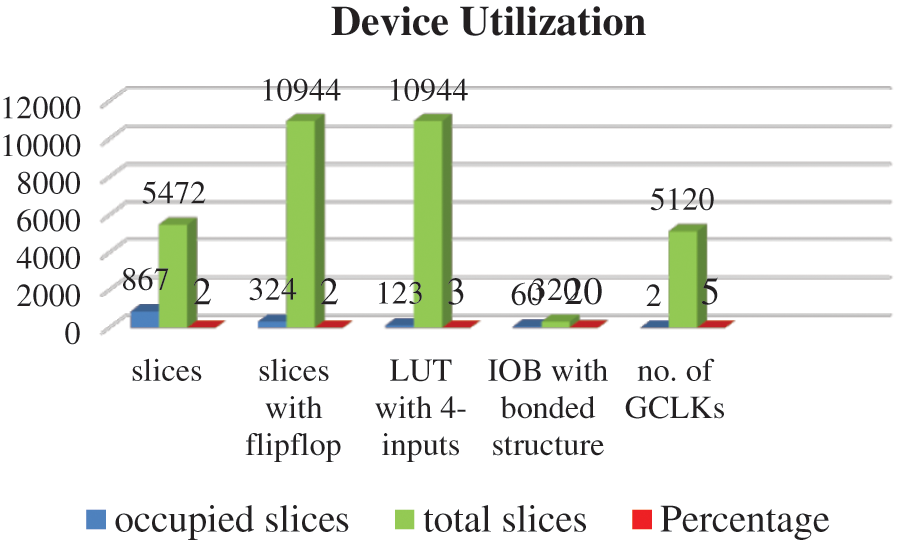
Figure 8: Device utilization

The comparison of BER vs. SNR for OFDM utilizing PSK and QPSK is shown in Fig. 9, where the QPSK has lower DER and SNR modulation than the PSK and has extremely strong noise immunity. When compared to PSK, the bandwidth required for QPSK is half that of PSK for the same bit error rate. This has a low chance of error. The SNR value increased while the BER value fell in PSK and QPSK modulation.

Figure 9: BER vs. SNR for OFDM using PSK and QPSK
This research concludes by stating that the proposed Stepwise Exponential Companding technique reduces the complexity of the MIMO system. MIMO detection is performed in this technique by merging two techniques, IFFT and SEC. The QPSK detector with MIMO produces low SNR and BER. In the QPSK modulation method, one complex symbol encodes two binary bits. QPSK receivers are more advanced than PSK receivers due to the four states necessary to recover binary data information. QPSK is a less power-efficient modulation technique than other modulation types due to the aforementioned rationale, as two bits require more power to transmit. In the case of MIMO detection, however, overflow and quantization mistakes induced by the inherently limited precision frequently result in BER performance loss. As a result, the bit-resolution must be appropriately specified, and hardware complexity must be taken into mind. It can be expanded in the future to determine the Bit Error Rates of these complementary techniques when combined with another modulation technique.
Acknowledgement: The authors with a deep sense of gratitude would thank the supervisor for his guidance and constant support rendered during this research.
Funding Statement: The authors received no specific funding for this study.
Conflicts of Interest: The authors declare that they have no conflicts of interest to report regarding the present study.
1. A. Mokh, M. Helard and M. Crussiere, “Extended receive spatial modulation MIMO scheme for higher spectral efficiency,” in Proc. Vehicular Technology Conf., IEEE, Porto, Portugal, pp. 1–6, 2018. [Google Scholar]
2. S. H. Mirfarshbafan, M. Shabany, A. Aminiand and S. A. Nezamalhosseini, “Near-ML detection in massive MIMO systems with one-bit ADCs: Algorithm and VLSI design,” in Proc. Int. Symp. on Circuits and Systems, IEEE, Florence, Italy, pp. 1–5, 2018. [Google Scholar]
3. G. Anupma, V. Kumar and D. Praveen, “Performance analysis of MIMO OFDM system using BPSK & QPSK modulation techniques under Rayleigh fading channel,” International Journal of Advanced Research in Computer Engineering & Technology, vol. 5, no. 1, pp. 1–11, 2016. [Google Scholar]
4. A. S. Kushwaha, D. Pandey and A. Patidar, “MIMO configuration scheme with spatial multiplexing and QPSK modulation,” International Journal of Engineering Research and Application, vol. 2, no. 4, pp. 746–750, 2012. [Google Scholar]
5. A. Azizzadeh, R. Mohammadkhani and S. V. A. D. Makki, “BER performance of uplink massive MIMO with low-resolution ADCs,” in Proc. The Int. Conf. on Computer Engineering and Knowledge, Mashhad, Iran, pp. 298–302, 2017. [Google Scholar]
6. B. Yin, M. Wu, J. R. Cavallaro and C. Studer, “VLSI design of large-scale soft-output MIMO detection using conjugate gradients,” in Proc. Int. Symp. on Circuits and Systems (ISCAS), IEEE, Lisbon, Portugal, pp. 1498–1501, 2015. [Google Scholar]
7. B. Jose and M. B. S. Kumar, “Design of MIMO-OFDM SDM systems for high-speed data transmission,” International Journal of Information & Computation Technology, vol. 4, no. 1, pp. 1–8, 2014. [Google Scholar]
8. T. C. Zhang, C. K. Wen, S. Jin and T. Jiang, “Mixed-ADC massive MIMO detectors: Performance analysis and design optimization,” IEEE Transactions on Wireless Communications, vol. 15, no. 11, pp. 7738–7752, 2016. [Google Scholar]
9. L. Giarre, L. Jaccheri and I. Tinnirello, “Lecture notes in computer science book series,” in Proc. Int. Cost Engineering Council, Tsukuba City, Japan, vol. 10507, pp. 147–153, 2017. [Google Scholar]
10. D. Bactor, R. Kaur and P. Bactor, “Diversity techniques using BPSK and QPSK modulation in MIMO system under fading environment,” International Journal of Advanced Research in Electronics and Communication Engineering, vol. 4, pp. 33–41, 2015. [Google Scholar]
11. D. Wu, J. Eilert, R. Asghar and D. Liu, “VLSI implementation of a fixed-complexity soft-output MIMO detector for high-speed wireless,” EURASIP Journal on Wireless Communications and Networking, vol. 2010, pp. 1–13, 2010. [Google Scholar]
12. A. Appathurai and P. Deepa, “Design for reliability: A novel counter matrix code for FPGA based quality applications,” in Proc. Asia Symp. on Quality Electronics Design, IEEE, Kula Lumpur, Malaysia, pp. 56–61, 2015. [Google Scholar]
13. R. Zakaria and D. L. Ruyet, “On maximum likelihood MIMO detection in QAM-FBMC systems,” in Proc. Personal Indoor and Mobile Radio Communication, Istanbul, Turkey, pp. 183–187, 2010. [Google Scholar]
14. F. Jin, F. Cui, Q. Liu and H. Liu, “A unified model for signal detection in massive MIMO system and its application,” in Proc. Consumer Communications & Networking Conf., Las Vegas, NV, USA, pp. 1–2, 2019. [Google Scholar]
15. F. Ito, T. Nakagawa, H. Hamazumi and K. Fukawa, “Development of 4 × 4 MIMO-QPSK demodulator using complexity-reduced MLD with block QR decomposition,” in Proc. Broadband Multimedia Systems and Broadcasting (BMSB), Nara, Japan, pp. 1–4, 2016. [Google Scholar]
16. I. A. Bello, B. Halak, M. E. Hajjar and M. Zwolinski, “VLSI implementation of a fully-pipelined K-best MIMO detector with successive interference cancellation,” Circuits, Systems, and Signal Processing, vol. 38, no. 10, pp. 4739–4761, 2019. [Google Scholar]
17. A. J. G. Malar, C. A. Kumar and A. G. Saravanan, “Iot based sustainable wind green energy for smart cites using fuzzy logic based fractional order darwinian particle swarm optimization,” Measurement, vol. 166, pp. 108208, 2020. [Google Scholar]
18. H. Wu, B. Shen, S. Zhao and P. Gong, “Low-complexity soft-output signal detection based on improved kaczmarz iteration algorithm for uplink massive MIMO system,” Sensors, vol. 20, no. 6, pp. 1564, 2019. [Google Scholar]
19. H. Wu, B. Shen, S. Zhao and P. Gong, “Low-complexity soft-output signal detection based on improved kaczmarz iteration algorithm for uplink massive MIMO system,” Sensors, vol. 20, no. 6, pp. 1564, 2020. [Google Scholar]
20. Z. Cai, Y. H. Wang and S. Chattong, “A low complexity and high throughput MIMO detection VLSI design for MIMO-OFDM systems,” in Proc. Vehicular Technology Conf., Springer, Nanjing, China, pp. 1–5, 2016. [Google Scholar]
21. A. Kosasih and O. Setyawati, “Low complexity multi-user MIMO detection for uplink SCMA system using expectation propagation algorithm,” Telkomnika, vol. 16, no. 1, pp. 182–188, 2018. [Google Scholar]
22. C. H. Yang, “Massive MIMO detection VLSI design,” in Proc. VLSI-Design and Test, Hsinchu, Taiwan, pp. 1, 2018. [Google Scholar]
23. E. P. Adeva, T. Seifert and G. Fettweis, “VLSI architecture for MIMO soft-input soft-output sphere detection,” Journal of Signal Processing Systems, vol. 70, no. 2, pp. 125–143, 2013. [Google Scholar]
 | This work is licensed under a Creative Commons Attribution 4.0 International License, which permits unrestricted use, distribution, and reproduction in any medium, provided the original work is properly cited. |