DOI:10.32604/iasc.2022.023093
| Intelligent Automation & Soft Computing DOI:10.32604/iasc.2022.023093 | |
| Article |
Optimized Control of Single Phase Reboost Luo Converter Fed Grid-Connected PV System
1Jeppiaar Institute of Technology, Chennai, 631604, India
2Velammal Engineering College, Chennai, 600066, India
*Corresponding Author: S. Baskaran. Email: baskaran.sa1985@gmail.com
Received: 27 August 2021; Accepted: 25 November 2021
Abstract: An epic topology of PV system for 1Ф grid tied framework with high gain altered Re Boost Luo converter is developed. In this epic topology, the PV (Photovoltaic) system is connected with single phase network via a Re Boost Luo converter and Voltage Source Inverter. The voltage variance issues of PV framework are overwhelmed by extricating most extreme power from the array. The Whale Optimization is utilized to extract the vast majority of the power from photovoltaic array. Similar to the existing topology, the proposed scheme is designed using reference casings of direct and quadrature hub components. The Re Boost Luo converter acquires the benefits contrasted with traditional DC-DC converter scheme. The Whale Optimization Algorithm based closed loop control logic gives magnificent execution under different testing conditions and the results are compared with Fuzzy based calculation. The PWM (Pulse Width Modulation) generator is utilized for triggering the inverters and converter. The Re boost Luo converter switches are made from silicon carbide to diminish the exchanging misfortunes better than traditional switches. Unfaltering state and momentary reaction of the controller are examined to know the excellence of the proposed novel system. Thus a high voltage gain is attained through the proposed converter and control algorithm. The grid current synchronization is accomplished via ANN (Artificial Naural Natwork) controller so that the THD (Total Harmonic Distortion) is reduced to fulfill the IEEE standard. Thus the proposed framework decreases the power quality issue of 1Ф grid system fed by the PV system. The outcomes are verified with Matlab recreation tool and DSPIC30F2010 controller.
Keywords: 1Ф grid system; PV system; re boost-luo converter; fuzzy based closed loop control algorithm; whale optimization method; DSP controller
Distributed power generation based on renewable energy sources like PV and Wind generation framework is taking part in contributing environmentally friendly power production [1–5]. The oscillatory yield voltage and irregular source current from a PV panel incorporates a more elevated level of swell substance and halfway concealing impact. The PMSG (Permanent Magnet Synchronous Generator) changes wind energy into 3Ф electric power. As the PMSG yield is inconsistent, the higher request harmonics are injected because of Permanent Magnet and natural oscillation [6–12].
In [13], the author suggested a couple of methodologies with their favorable circumstances and disservices. It is hard to pick the best choice with the accessible such a significant number of system. The significant features that are considered when choosing specific calculation are the simplicity in execution, number of panels required, the event of different neighborhood maxima, fiscal expenses and region of use. The DG (Distributed Grid) requires consistent power and voltage so as to achieve consistently high power activity using dc to dc converter. In conventional methods, transformer dependent framework associated PV system is utilized [14–18]. The transformer is of significantly expensive and the spillage reactance issues also build up with additional galvanic seclusion. The Boost converter alternates the transformer dependent matrix associated dissemination framework. Also the boost converter topology keeps up ceaseless source current with single recurrence and yield swell concealment. The various calculations are utilized to keep up consistent voltage activity [19–23]. The boost converter just lifts the yield potential with low yield voltage gain and high swell substance. Buck-boost converter beats the disadvantages of existing lift converters. It does both buck and lift activity with single recurrence concealment in the yield potential however the converters may produce intermittent flow activity. This expands the exchanging misfortune and lessens the system performance.
A hypothetical parallel input parallel output (PIPO) converters are proposed in [24] which contain 2 fell periods of buck-lift and lift for acquiring higher potential enhancement and galvanic segregation at proper commitment ratio and lower vitality leak. Various dispersed generators are related to DC organize through PIPO method using the presented converter is a non resistive hot model all through DGs in handy application. The Cuk and SEPIC converter defeat the impediments of conventional step down-up and lift topology with minimum yield potential expansion.
A new analysis of two guideline parameters depicting the P&O calculation is presented in [25]. This streamlining method tweaks the P&O (Perturb & Observe) variables for the active conduction made by the suitable converters and to enhance PV performance. The result shows that the viability and flexibility of the P&O procedure is manhandled by upgrading it as the dynamic behavior of the system. The most elevated power of the solar and wind framework is obtained from approach. P&O method can bolster the dc to dc converter and this method is utilized for low power application. Gradual conductance and hill climbing calculation are employed to conquer the downsides of P&O method at the cost of exceptionally low precision.
By defeating the downsides of calculation, PI controller combines with the enhancement method to extricate majority of the power from a PV panel to give high performance. Another IC controller based obligation proportion computation with direct control is proposed in [26,27] to dispose of inconvenience of steady conductance calculation. A Fuzzy Logic (FL) is recommended to estimate the obligation proportion for pursuing the most optimal power point from a PV panel. This technique accomplishes most extreme power point even more definitely different in relation to fixed development methodology and speedier under balanced active and reliable state condition. The results confirm the advantages of our method. In this paper, the customary downsides are overwhelmed by a single switch higher yield Re Boost Luo converter. To keep up at high proficiency and to lessen the ripples, Fuzzy based closed loop approach combined with exceptionally proficient whale optimization is utilized.
2 Proposed Re Boost Luo Converter
The Re boost LUO converter is a topology based on a dc to dc buck–boost converter that can overcome the constarints of existing converters in solar PV systems.
The novel design of Re boost LUO converter incorporates both a Super lift LUO and Fly back converter. The input current of the proposed converter becomes continuous due to the transformers’ source side winding. The two modes of working are described, as well as the ON and OFF durations of switch.
During the switch ON condition, the isolation transformer’s magnetizing inductance charges, the diodes D1 and D2 are turned OFF, the capacitors C1 and C2 are in the condition of discharging.
This Fig. 1 shows that the proposed converter’s direction of current, while the period of ON and OFF. Assume that the converter works in continual conduction phase as well as the unfaltering stage characteristic for each switching is split into two modes. The equivalent circuit for each mode is given below (Figs. 2 and 3).
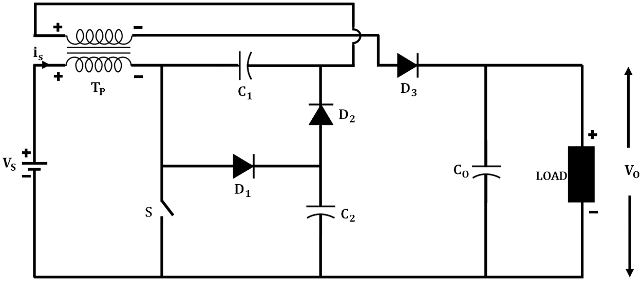
Figure 1: Proposed positive output re boost luo-converter circuit diagram
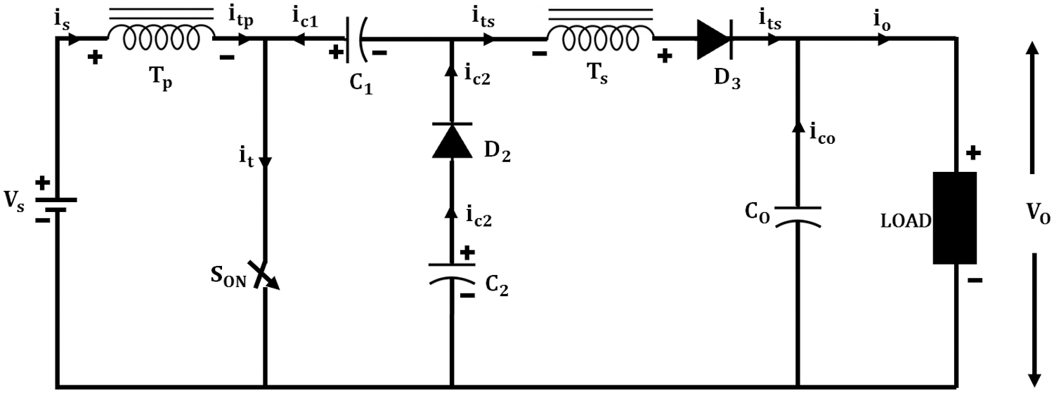
Figure 2: Current direction in switch ON mode of Re Boost Luo converter
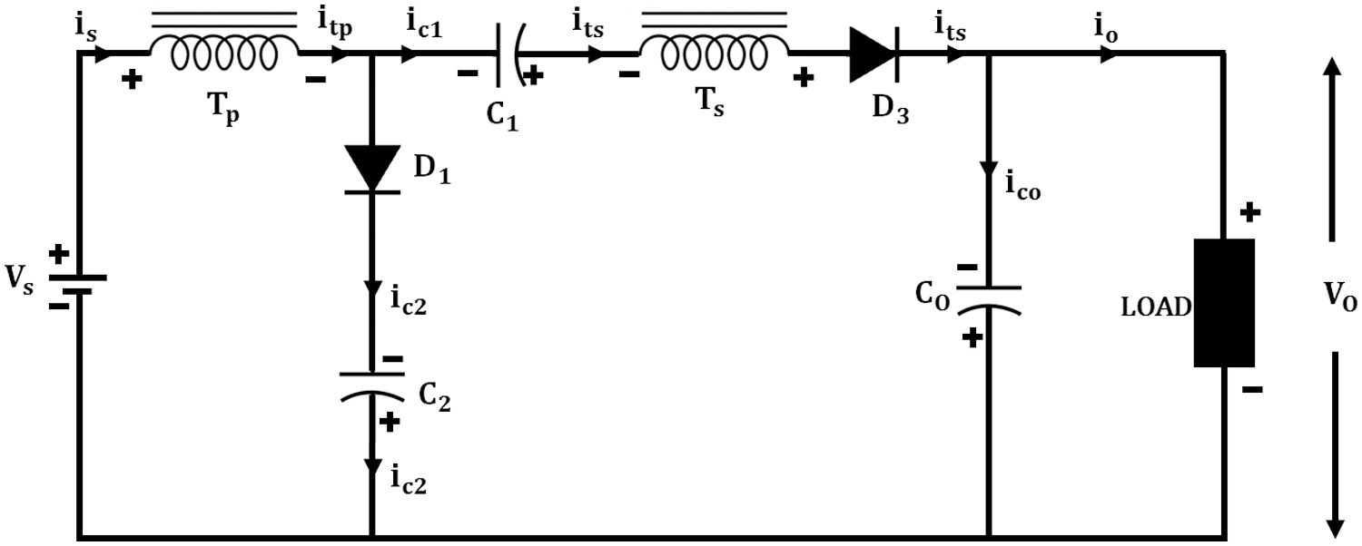
Figure 3: Direction of current during switch off mode of Re Boost Luo converter
Mode 1 Operation
When the operation starts, the switch S gets turned ON, which makes the current to pass via the isolation transformers primary (1°) winding, the transformer’s magnetizing coil of secondary (2°) winding does not conduct. On the other hand, the capacitance C1 is triggered up by the capacitance Co, which is mentioned as charge mode owing to the last working mode of diode D3 forward biased (FB) period. Meanwhile the output capacitance Co is detached from the left side of the circuit and the diode D2 is in OFF state as well as the capacitance Co discharged via the load resistor RL output. The current flow in this mode is presented in Fig. 2.
Mode 2 Operation
In this mode, the switch S is turned OFF. This time the direction of flow via the primary of transformer has not varied, it follows the same direction as Mode 1, so the charcteristics of input current are similar as analogized to different converters. In this mode the diode D1 in the FB is turned ON and D2 is turned OFF. The capacitance C2 is triggered by diode D1, and the capacitance C1 is triggered by the last stage, plus the charge of the primary inductor, which flows through the secondary winding of transformers to the output capacitance C0 and triggers the capacitor output, which is analogoized between higher voltage level and input voltage. The voltage level is regulated by limiting the duty cycle as well as frequency. The current flow direction during MODE 2 is shown in Fig. 3.
Design of Reboost-Luo Converter
The Novel Re BOOST Luo converter, which analyzed with the input voltage of 20–70 V DC
Expected base voltage = 200 V
Vin = 20 V
Vout = 200 V
The output potential of Re Boost–Luo converter is expressed as,
Turns Ratio:
The number of turns in isolation transformer, which is expressed as,
The duty cycle’s initial value is taken, i.e., α = 0.5
= 10 × 0.33
= 3.33(∼3)
Therefore turns ratio need to be used here is 1:3 where
Output Gain:
Output gain is computed from,
= 3.33(1.5/0.5)
= 3.33 × 3
G = 9.99
Gain output G = 10
Resistance in Load:
In novel system targeted output power = 200 w,
Iout = 1 Amps
Load Resistance
RL = 200 Ω
Voltages in Capacitor:
Voltage across each capacitor,
The voltage across the capacitances C2 and C3, which are expressed as,
= 3 × 20
The voltage across the capacitance C4, is Vo = 200 V
From Tabs. 1 and 2 we can come to a conclusion that the proposed Re-boost converter has a better performance compared to other topologies which we have taken for comparison. The proposed topology makes use of single switch which aids in achieving better controllability as designing a control scheme for a single switch converter is simple. The converter doesn’t need any inductors it uses only a single isolation transformer reducing the no of passive components. The proposed converter uses 3 diodes so it can tolerate voltage and current stress, which gets distributed among these diodes. In Tab. 2 we can see that the Re-Boost converter was a higher voltage gain compared to others topologies. While using a transformer with 1:3 turns ratio we get a gain of 9.


The converter accomplishes twofold recurrence swell concealment in the yield potentials. It also builds up the general framework performance to such an extent that with less obligation cycle, it underpins higher yield potential gain. The whale optimization gives maximum tracking of power from the PV supply and increments the proficiency of the converter. The responsive power at the grid side is expanded because of the nonlinear load. Because of the nonlinear grid attributes, the flow became non-uniform and the power quality turn into a significant issue at the lattice side which is a significant issue which influences the performance of the lattice. In this work, the PI controller is used to compensate framework current and this makes network to accomplish a unity control factor. At last the proposed framework accomplishes higher steadiness in potential at the lattice side. The proposed method is a network associated hence it doesn’t require any stockpiling framework. With this topology, the proposed Re Boost Luo converter attains 90% productivity, the fluffy rationale based closed loop and whale optimization further expands the proficiency.
The Re Boost Luo converter is intended to function in continual conduction state with minimum stress on the power equipments as well as its components regardless of the irradiance variation level. Supplementary phase current sensors or associated circuitry and controllers are not required.
This dc potential is given to the Re Boost Luo-converter, because of the change in illumination, the PV yield potential have higher request swell substance likewise fractional concealing impact emerges, this modifying potential is given to the converter. Two distinct strategies are accessible for associations (series and parallel association). In this paper, parallel activity is accomplished to achieve ceaseless supply potential. The circuit layout of this proposed work is represented in Fig. 4.
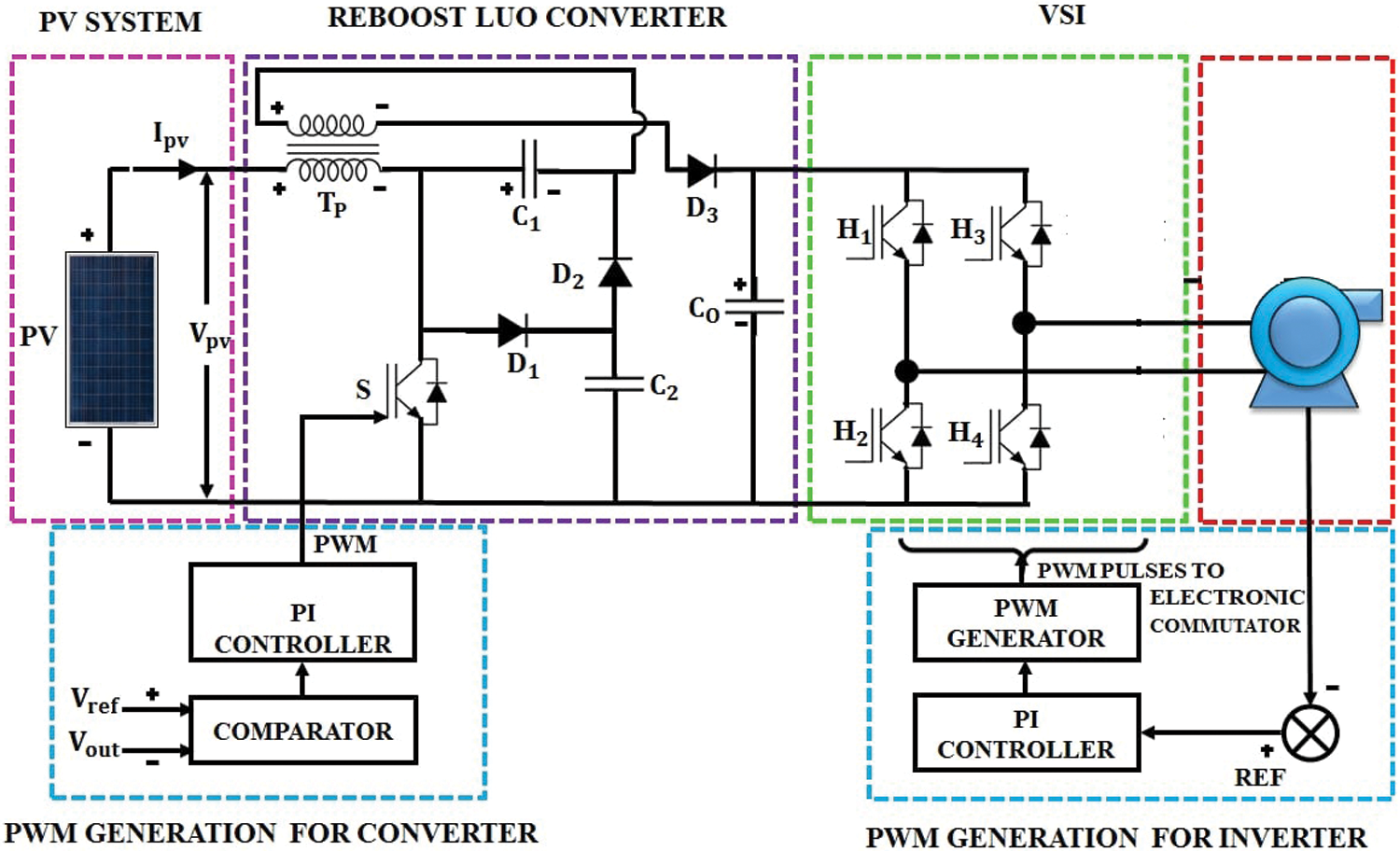
Figure 4: Circuit diagram of proposed system
Re Boost Luo-converter has 1 cascade inductance and 1 parallel capacitance. This decreases swelling from the source potential and flow. The Re Boost Luo-converter with cascaded inductance and diode blend mitigates fractional concealing impact. The primary advantage of Re Boost Luo-converter is its continuous source current and high yield potential gain.
The reference voltage and flows are estimated from the source side by executing closed loop calculation. The reference sign and the 10 kHz triangular bearer sign are contrasted and the pulses are fed to the Re Boost Luo converter switch. The closed loop calculation accomplishes consistent yield potential with decreased swells in voltage. This potential is given to the VSI (Voltage Source Inverter). The 1Ф VSI converts the dc potential into ac as throbbed yield potential. This throbbed ac potential is fed to the inductive channel to make it as a sine yield potential. This potential is applied to the 1Ф power line. Because of non linear load, a harmonic is infused into the source potential and flow. Subsequently to keep away the harmonic, the real potential and flow are measured from the power line. The ideal power is considered as a reference and contrasted with real power. The PI controller dependent power line synchronization is accomplished to remunerate responsive power.
A. PV Panel Modeling
The PV system model is illustrated in Fig. 5.
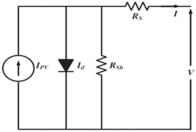
Figure 5: One diode model of the PV panel
Where
IPV-Photovoltaic current; Id-diode current; Rsh-Shunt Resistor; Rs-Series resistor;
I-yield flow
V-yield potential from PV panel
The current attained from the PV panel, which is expressed as,
where
Io→ Saturation current; Vk→ Maximum Thermal Voltage; α→ Diode ideality Constant
Four PV panels are utilized in the proposed work. The outcome from the PV is fed to the Converter.
B. Control strategies for Re Boost Luo Converter
The control mechanism used in this work based whale algorithm (Fig. 6).
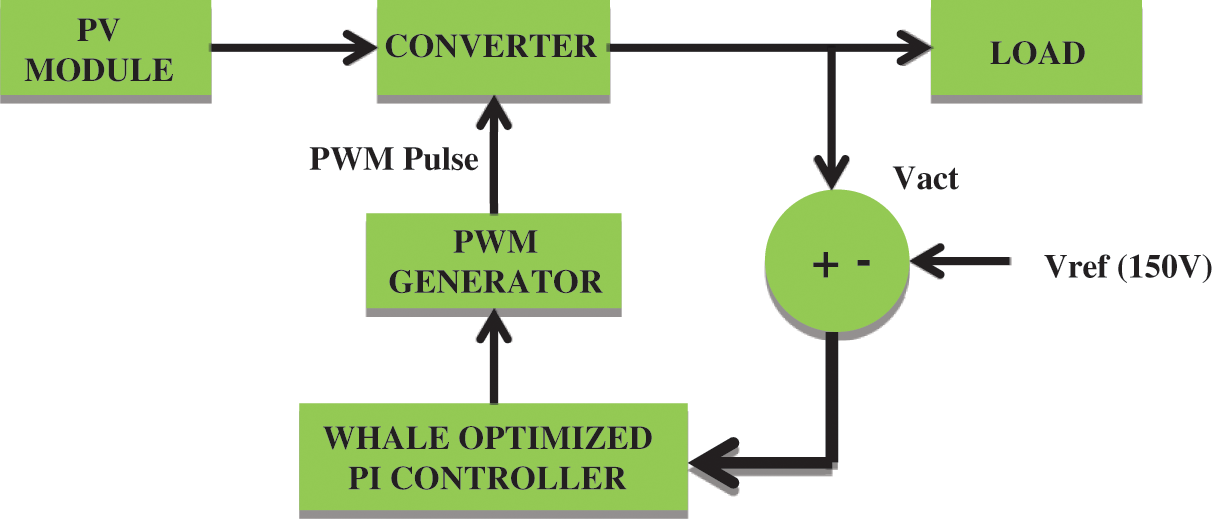
Figure 6: Control strategy for Re Boost luo converter
The purpose of the controller is to adjust the outcome voltage of the converter. For that purpose, a comparator is used to analogize the actual of VDC with Vref. The error is sent to the PI controller. The control variables are adjusted by the whale algorithm. Lastly, the controlled signal produces a reference signal, which is analogized with carrier signal. On this basis, the pulses are produced, which is given to the Re Boost Luo converter.
C. Whale Optimization (WO) Method based closed loop converter control
The Whale Optimization Method is roused from the foam chasing method of humpback whales. The humpback whale is the greatest of all whales and it has unique chasing system of winding bubble-net sustaining. The whales chase the fishes or krill the surface by making peculiar bubbles in a round way.
Humpback whales encompass its food during the chase and its circling attribute is scientifically expressed as
where, D, A & C are the vector coefficients, k is the present iteration, X* is the optimal answer and it gets updated in each cycle if more optimal answer is received, X is the location vector of the whale. The A vector and C vector are estimated as
where, reduced linearly from 2 to 0 over repeated time and r is an arbitrary vector between [0,1]. Here we indicate X* as the better solution with details about the site of prey.
WO has the potential to achieve a global optimal solution while avoiding local optima. Because of these benefits, WO is considered as an ideal technique for tackling many bounded or unbounded optimization problems in real applications without requiring structural remodeling.
Application of WO method for closed loop control
The maximum power is designed as an objective function and it is regarded as follows:
where, P is PV yield power, d is duty cycle, dmin and dmax are the lower and upper limit of duty cycle i.e., 0.1 and 0.9, respectively.
Here WOA is executed to directly control the maximum power output of converter by directly controlling the duty ratio by considering population of whales as duty ratio to decrease steady state oscillation. The straight control of minimizing the loss of power increases system efficiency. For each population of whales (duty cycles), the respective voltages and currents are estimated from controller to estimate the output power.
For maximum power, (11) is modified as
The objective function of WOA is arranged as
where i is the population of whales
Also PV power depends on environmental condition, hence as solar irradiation of PV modules varies, the power output from PV array also varies correspondingly and proposed algorithm is reassumed by measuring the change in PV output power using (14).
By utilizing the whale algorithm to adjust the Kp and Ki parameters, the PI controller generates a reference sigal, which is analogized with the carrier signals to produce the PWM pulses and it is given to Re Boost Luo Converter.
D. Fuzzy logic Algorithm
The output from a PV panel is unreliable as the solar light exposed tends to change. Thus, it is hard to accomplish productive activities of the framework. So as to obtain trustful yield and to improve proficient activity, an optimum power following strategy is utilized. The closed loop control strategy continually screens the yield from a PV system. In the event that there is a change in the yield power, the active region of the control algorithm changes to a noteworthy point. This technique may be rehashed in any event by moving the operating region in inverse way when the output is low. The proposed control algorithm is basically a simple and trustful method for effective activity of sustainable energy based power generation framework, which is represented in Fig. 7a. In this paper, a fluffy rationale based control calculation is actualized [6].
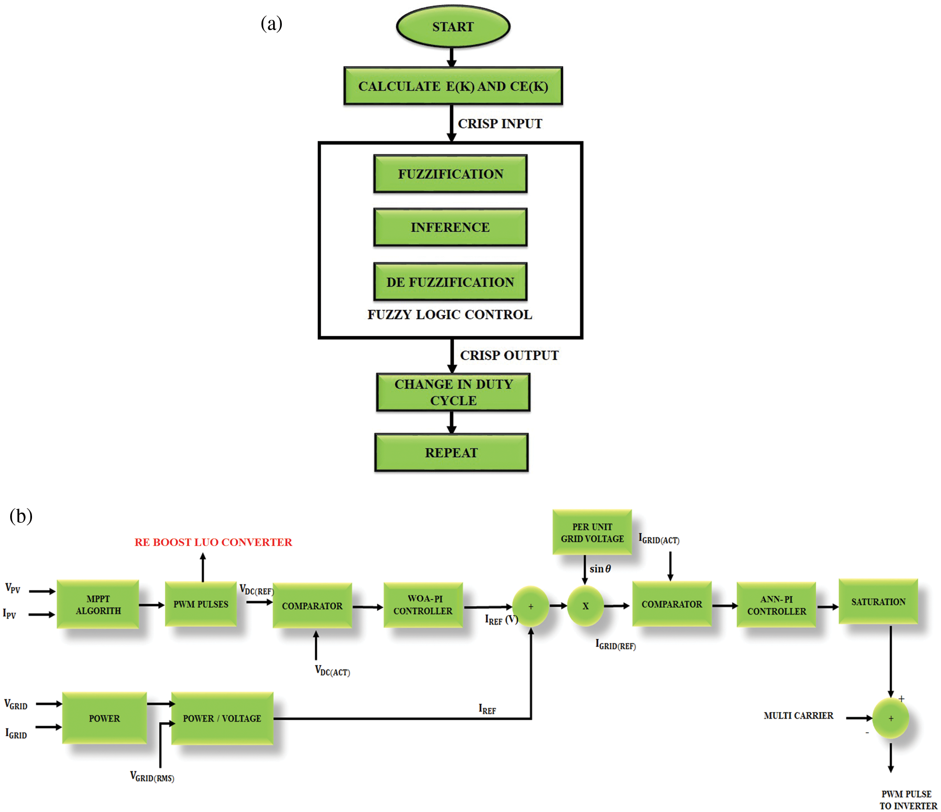
Figure 7: (a) Flow chart of fuzzy logic based control algorithm (b) Grid synchronization control strategy by utilizing ANN-PI controller
The most popular strategy of MPPT (Maximum Power Point Tracking) is P&O approach. The P&O efficiency is low owing to slow convergence speed and steady state output oscillation near the point of maximum power. If the system operates near the maximum power area, it causes the duty cycle to increase or decrease, depending on the change in the PV voltage. This generates a fluctuations in the steady state output. To ignore the generated fluctuations and to attain a stable outcome voltage, fuzzy maximum power tracking is employed. To regulate non-linearity and uncertainty associated with PV systems, this strategy is employed. The intelligent fuzzy based control is introduced to track the optimal power point (OPP) of the PV system. The inputs of the controller comprises error (e) as well as change in error (ce). The proposed strategy is based on the input and output variables. The control algorithm provides duty cycle commands to change the working point of the PV panel to obtain high outcome of power. The input parmeters utilized for control are the slope of the PV curve and the change in slope.
As the slope disappears at MPP, inputs are estimated as
where,
VPV = PV Voltage; PPV = PV Power, e(k) denotes the PV curve slope, which decides the position of PV panel’s MPP. Ce describes whether the movement of working point is in MPP way or not.
Fig. 7b describes the schematic model of gid synchronization using ANN-PI controller. The actual potential of Photo Voltaic inverter (Vdc) is taken and forward to LPF (Low Pass Filter) to decrease the switching ripples. The error of the channeled dc potential as well as base potential
The voltage error (Verr) in nth sampling time is
The outcome of the PI at nth sampling time, which is expressed as,
where, KP1 and KI1 are proportionality as well as integral gain of controller. The resulted voltage of the controller is the high amplitude of the current at active state which is then integrated with the voltage in the grid to produce the base current for the Photo Voltaic inverter. By this control method, the PV inverter can give the local load with a maximum current up to base value. If the requirements of load are high, the additional currents, which are obtained from the grid.
During this state, the actual inverter current is contrasted with the base esteem. The errors are powered to PI controllers. The yield of the PI controllers produces a change in the duty cycle and mixes with the static duty cycle (D) to create a modulating signal.
The experimentation of our work is done in MATLAB simulink. The same is also proved by using DSPIC30F2010 controller. Tabs. 3 and 4 describes the specificiations of the PV system as well as Re Boost Luo Converter. The experimental setup is depicted in Fig. 8.

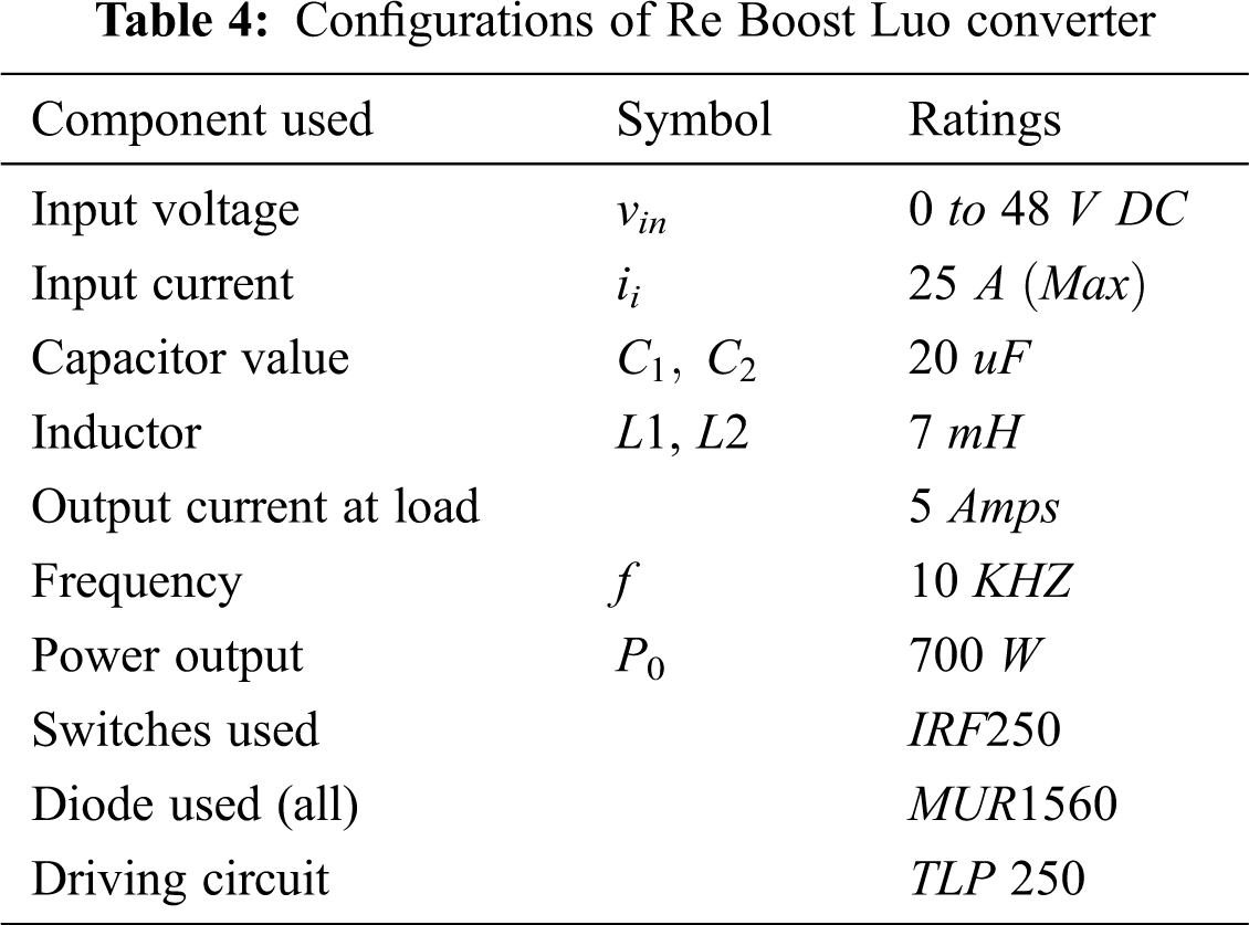
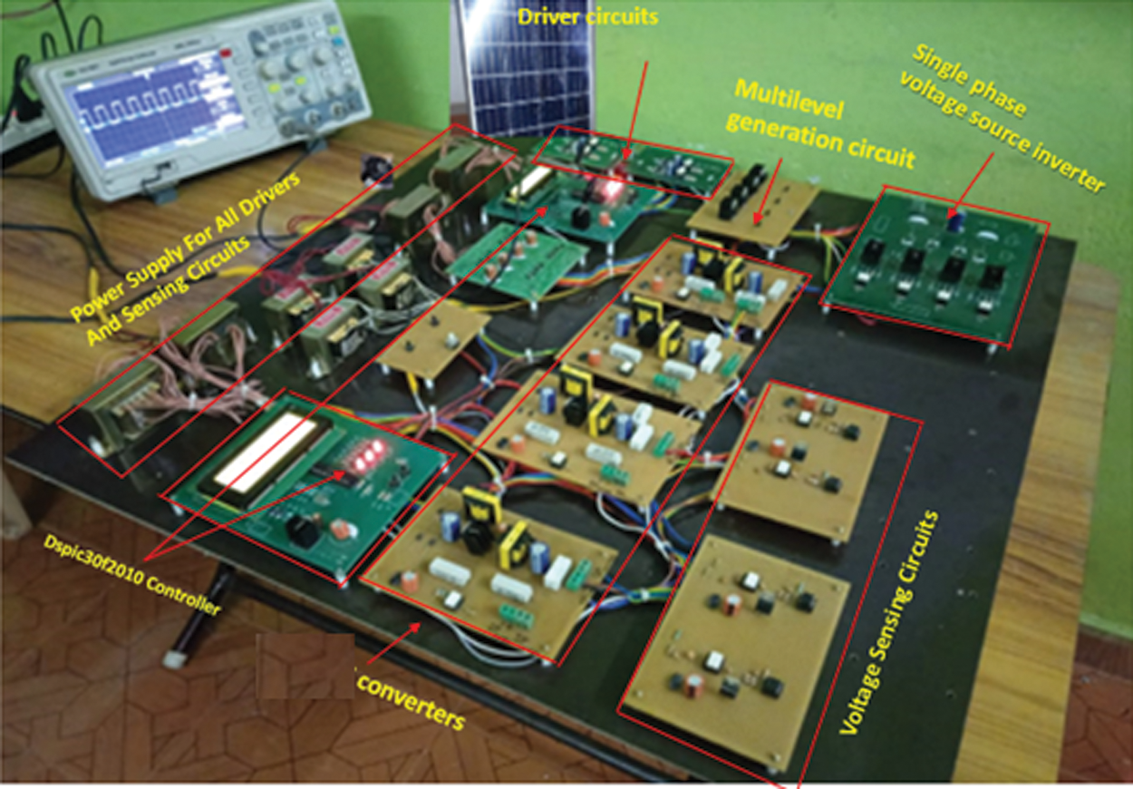
Figure 8: Hardware setup
The Figs. 9a and 9b show the yield potential of the Re Boost Luo converter using FL algorithm.
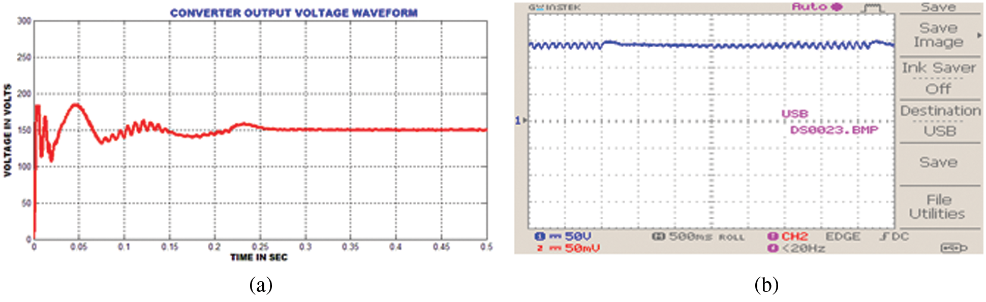
Figure 9: (a) Simulation results of Re Boost Luo converter yield potential using FL (b) Hardware results of Re Boost Luo converter yield potential using FL
The Figs. 10a and 10b represent the yield potential of the ReBoost Luo converter using whale optimization. Contrasted with Fuzzy logic, it gives more stable voltage.
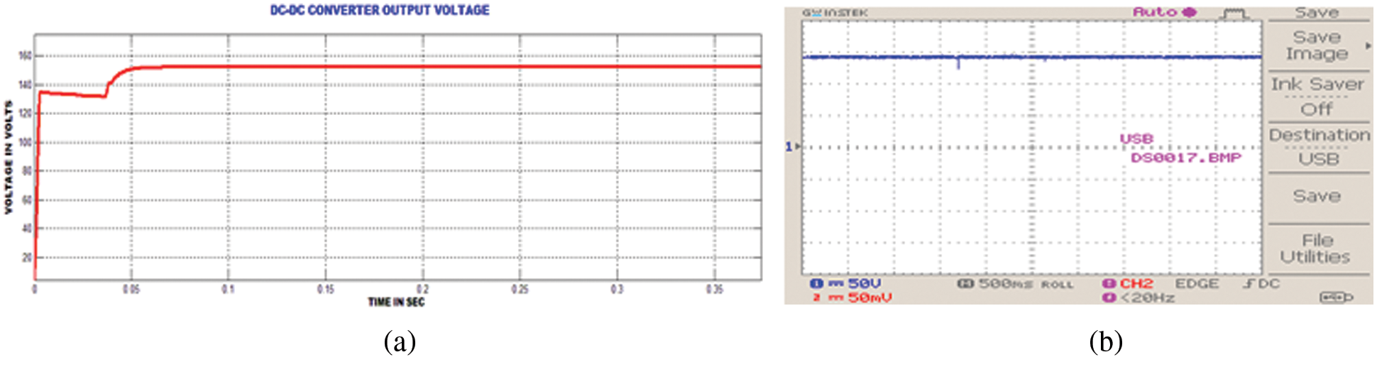
Figure 10: (a) Simulation results of Re Boost Luo converter yield potential using whale optimization method (b) Hardware results of Re Boost Luo converter yield potential using whale optimization method
The Figs. 11a and 11b shows the Re Boost Luo converter’s output waveform. Due to nonlinear load, current have noises.
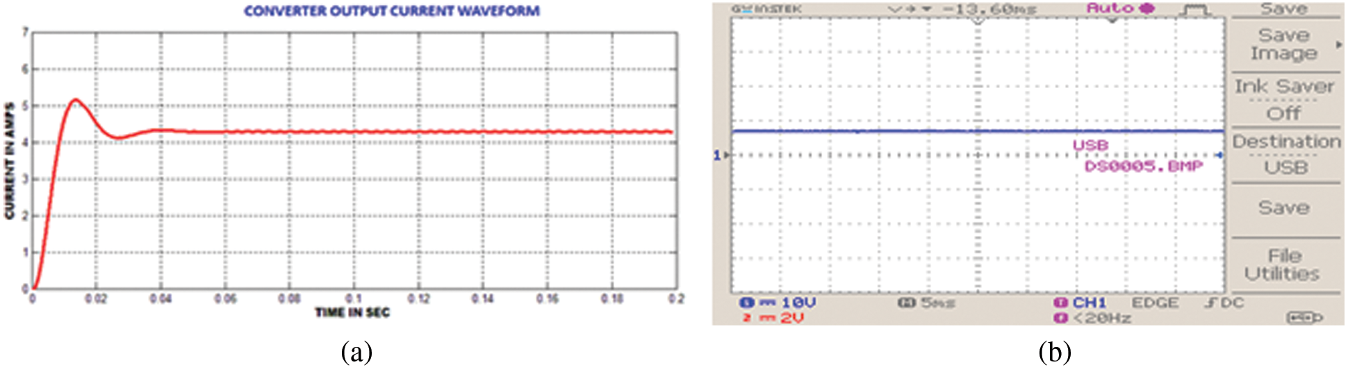
Figure 11: (a) Re Boost Luo converter’s output current (b) Re Boost Luo converter’s output waveform
The Fig. 12 represents the in phase potential and flow of grid. Thus the unity power factor is maintained. Thus the total system behaves like STATCOM.

Figure 12: Hardware results of grid voltage and current waveform
The Fig. 13a is the THD of supply potential which shows only 1.18%. Thus the system achieves IEEE standard of harmonics level. The Re Boost Luo-converter and proposed control keeps fixed potential with the grid using inverters. Thus the PI controller has achieved steady grid operation.
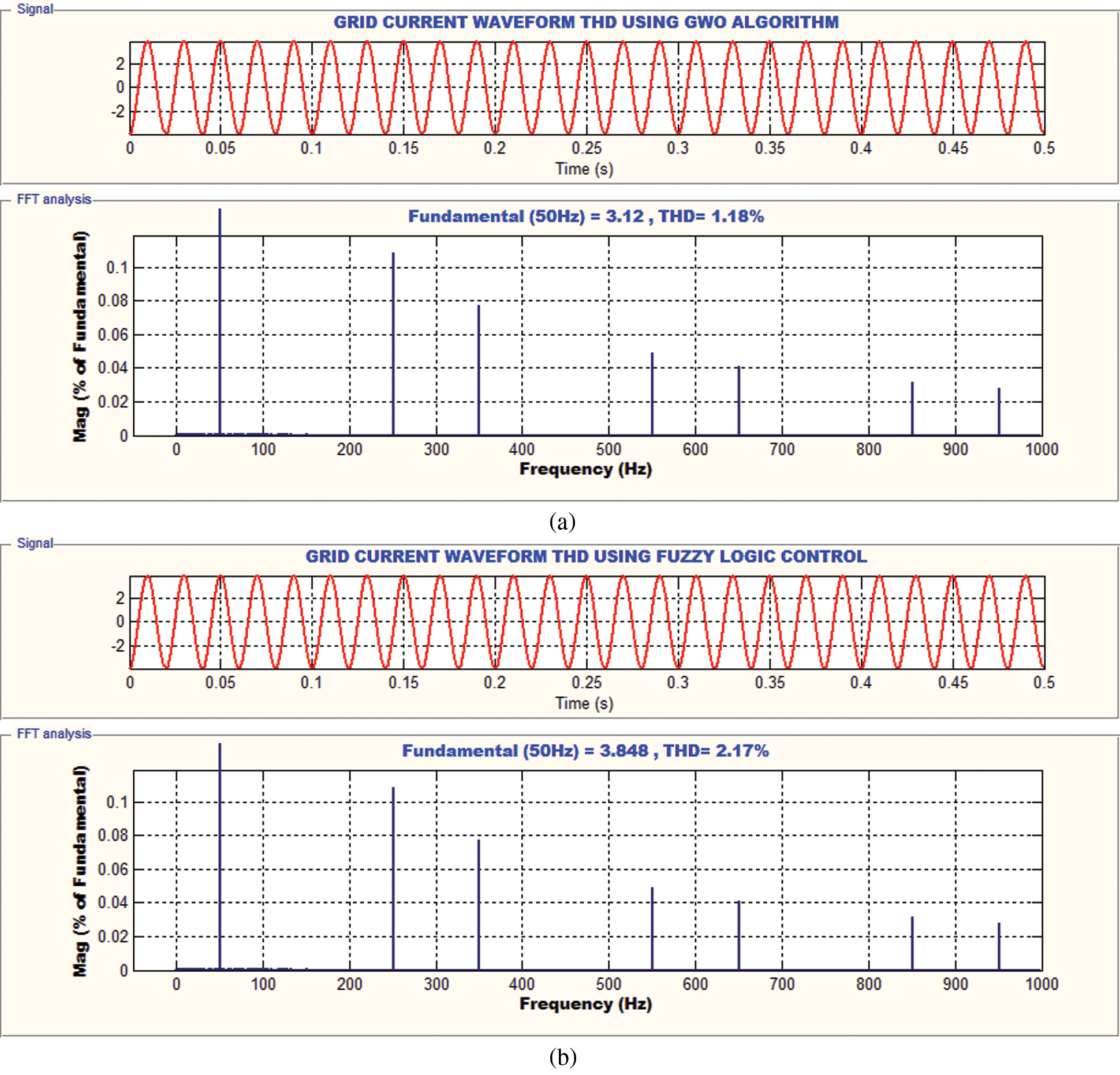
Figure 13: (a) Grid current THD with whale algorithm. (b) Grid current THD with fuzzy logic algorithm
Comparison of Controllers
The proposed system is verified with FL and whale optimization based closed loop control algorithm, which is portrayed in Tab. 5.
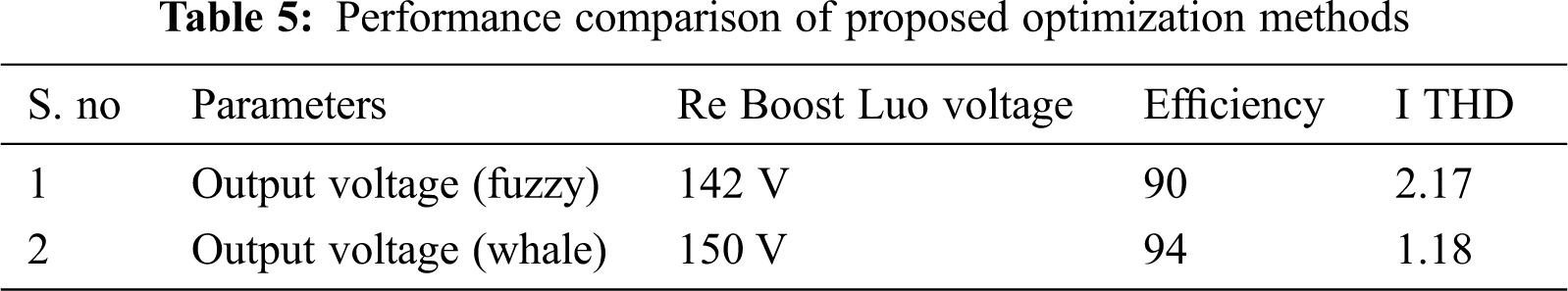
In this work PV based Re Boost Luo converter has been successfully realized for distributed systems. The overall system performance is studied in MATLAB somulink and DSPIC30F2010 controller. The FL algorithm plucks out most of the power from the PV sources and when comparing to other algorithms, it delivers the reduced ripples by utilizing the Re Boost Luo converter. Here PI controller is used to achieve grid current synchronization and produces less THD. Thus the inverter satisfies the power quality and harmonic standard level. Comparison is made between fuzzy and whale optimization. The Re Boost Luo-converter with FL and whale optimization based control algorithm provides satisfied achievement. This system is used for the compensation of responsive power in smart and power grid.
Funding Statement: The authors received no specific funding for this study.
Conflicts of Interest: The authors declare that they have no conflicts of interest to report regarding the present study.
1. F. H. Aghdam and M. Abapour, “Reliability and cost analysis of multistage boost converters connected to PV panels,” IEEE Journal of Photo Voltaic, vol. 6, no. 4, pp. 981–989, 2016. [Google Scholar]
2. D. Apablaza and J. Munoz, “Laboratory implementation of a boost interleaved converter for PV applications,” IEEE Latin America Transactions, vol. 14, no. 6, pp. 2738–2743, 2016. [Google Scholar]
3. G. R. C. Mouli and J. H. Schijffelen, “Design and comparison of a 10-kW interleaved boost converter for PV application using Si and SiC devices,” IEEE Journal of Emerging and Selected Topics in Power Electronics, vol. 5, no. 2, pp. 610–623, 2017. [Google Scholar]
4. M. Arjun, V. V. Ramana, R. Viswadev and B. Venkatesaperumal, “Small signal model for PV fed boost converter in continuous and discontinuous conduction modes,” IEEE Transactions on Circuits and Systems, vol. 66, no. 7, pp. 1192–1196, 2019. [Google Scholar]
5. D. Das, S. Madichetty, B. Singh and S. Mishra, “Luenberger observer based current estimated boost converter for PV maximum power extraction—a current sensor less approach,” IEEE Journal of Photo Voltaic, vol. 9, no. 1, pp. 278–286, 2019. [Google Scholar]
6. P. Shaw, “Modeling and analysis of an analogue MPPT-based PV battery charging system utilizing dc–dc boost converter,” IET Renewable Power Generation, vol. 13, no. 11, pp. 1958–1967, 2019. [Google Scholar]
7. F. Reverter and M. Gasulla, “Optimal inductor current in boost DC/DC converters regulating the input voltage applied to low-power photovoltaic modules,” IEEE Transactions on Power Electronics, vol. 32, no. 8, pp. 6188–6196, 2017. [Google Scholar]
8. M. Ammirrul, A. M. Zainuri and M. A. M. Radzi, “Development of adaptive perturb and observe-fuzzy control maximum power point tracking for photovoltaic boost dc-dc converter,” IET Renewable Power Generation, vol. 8, no. 2, pp. 183–194, 2014. [Google Scholar]
9. S. K. Kollimalla and M. K. Mishra, “Variable perturbation size adaptive P&O MPPT algorithm for sudden changes in irradiance,” IEEE Transactions on Sustainable Energy, vol. 5, no. 3, pp. 718–728, 2014. [Google Scholar]
10. J. Ahmed and Z. Salam, “An enhanced adaptive P&O MPPT for fast and efficient tracking under varying environmental conditions,” IEEE Transactions on Sustainable Energy, vol. 9, no. 3, pp. 1487–1496, 2018. [Google Scholar]
11. R. Errouissi, A. A. Durra and S. M. Muyeen, “A robust continuous-time MPC of a DC–dc boost converter interfaced with a grid-connected photovoltaic system,” IEEE Journal of Photovoltaic, vol. 6, no. 6, pp. 1619–1629, 2016. [Google Scholar]
12. A. M. Rao and K. Sivakumar, “A fault-tolerant single-phase five-level inverter for grid-independent PV systems,” IEEE Transactions on Industrial Electronics, vol. 62, no. 12, pp. 7569–7577, 2015. [Google Scholar]
13. Y. Yang, F. Blaabjerg and H. Wang, “Low-voltage ride-through of single-phase transformerless photovoltaic inverters,” IEEE Transactions on Industry Applications, vol. 50, no. 3, pp. 1942–1952, 2014. [Google Scholar]
14. J. Huang and K. Li, “Suppressing EMI peaks through auto-screening carrier phase-shift scheme in a PV system composed of parallel single-phase inverters,” IEEE Transactions on Electromagnetic Compatibility, vol. 61, no. 1, pp. 82–89, 2019. [Google Scholar]
15. X. Q. Guo, “A novel CH5 inverter for single-phase transformerless photovoltaic system applications,” IEEE Transactions on Circuits and Systems II: Express Briefs, vol. 64, no. 10, pp. 1197–1201, 2017. [Google Scholar]
16. A. E. Khateb, N. A. Rahim and J. Selvaraj, “Fuzzy-logic-controller-based SEPIC converter for maximum power point tracking,” IEEE Transactions on Industry Applications, vol. 50, no. 4, pp. 2349–2358, 2014. [Google Scholar]
17. K. Nathan, S. Ghosh, Y. Siwakoti and T. Long, “A new DC–DC converter for photovoltaic systems: Coupled-inductors combined Cuk-SEPIC converter,” IEEE Transactions on Energy Conversion, vol. 34, no. 1, pp. 1197–1201, 2019. [Google Scholar]
18. N. Pragallapati and V. Agarwal, “Distributed PV power extraction based on a modified interleaved SEPIC for non uniform irradiation conditions,” IEEE Journal of Photovoltaics, vol. 5, no. 5, pp. 1442–1453, 2015. [Google Scholar]
19. S. S. Thale and V. Agarwal, “Controller area network assisted grid synchronization of a micro grid with renewable energy sources and storage,” IEEE Transactions on Smart Grid, vol. 7, no. 3, pp. 1442–1452, 2016. [Google Scholar]
20. S. K. Ma, H. Geng, L. Liu and G. Yang, “Grid-synchronization stability improvement of large scale wind farm during severe grid fault,” IEEE Transactions on Power Systems, vol. 33, no. 1, pp. 216–226, 2018. [Google Scholar]
21. S. Mukherjee, V. R. Chowdhury and P. Shamsi, “Power-angle synchronization for grid-connected converter with fault ride-through capability for low-voltage grids,” IEEE Transactions on Energy Conversion, vol. 33, no. 3, pp. 970–979, 2018. [Google Scholar]
22. M. G. Taul, X. Wang, P. Davari and F. Blaabjerg, “An overview of assessment methods for synchronization stability of grid-connected converters under severe symmetrical grid faults,” IEEE Transactions on Power Electronics, vol. 34, no. 10, pp. 9655–9670, 2019. [Google Scholar]
23. D. P. Estevez and J. D. Gandoy, “Grid-tied inverter with ac voltage sensor less synchronization and soft start,” IEEE Transactions on Industry Applications, vol. 55, no. 5, pp. 4920–4933, 2019. [Google Scholar]
24. S. Mohanty, B. Subudhi and P. K. Ray, “A new mppt design using grey wolf optimization technique for photovoltaic system under partial shading conditions,” IEEE Transactions on Sustainable Energy, vol. 7, no. 1, pp. 181–188, 2016. [Google Scholar]
25. N. Kumar, I. Hussain, B. Singh and B. K. Panigrahi, “Single sensor-based mppt of partially shaded pv system for battery charging by using Cauchy and Gaussian sine cosine optimization,” IEEE Transactions on Energy Conversion, vol. 32, no. 3, pp. 983–992, 2017. [Google Scholar]
26. H. Li, D. Yang, W. Su, J. Lu and X. Yu, “An overall distribution particle swarm optimization mppt algorithm for photovoltaic system under partial shading,” IEEE Transactions on Industrial Electronics, vol. 66, no. 1, pp. 265–275, 2019. [Google Scholar]
27. R. B. A. Koad, A. F. Zobaa and A. E. Shahat, “A novel MPPT algorithm based on particle swarm optimization for photovoltaic systems,” IEEE Transactions on Sustainable Energy, vol. 8, no. 2, pp. 468–476, 2017. [Google Scholar]
 | This work is licensed under a Creative Commons Attribution 4.0 International License, which permits unrestricted use, distribution, and reproduction in any medium, provided the original work is properly cited. |