DOI:10.32604/iasc.2022.023012
| Intelligent Automation & Soft Computing DOI:10.32604/iasc.2022.023012 | |
| Article |
Interleaved Boost Integrated Flyback Converter for Power Factor Correction in Brushless DC Motor Drive
1Department of Electrical and Electronics Engineering, Sree Sastha Institute of Engineering and Technology, Chennai, 600123, India
2Department of Electrical and Electronics Engineering, Sri Sivasubramaniya Nadar College of Engineering, Chennai, 603110, India
*Corresponding Author: S. Benisha. Email: nisha.beni@gmail.com
Received: 25 August 2021; Accepted: 09 November 2021
Abstract: The scope of this research is to manage the speed of Permanent Magnet Brushless DC Motor Drive (PMBLDCMD) for various less capacity applications. In the circuit, a 1ϕ AC power is given to Diode Rectifier and the converted DC supply is given to condenser, which leads to abnormal pulsating current. Because of this pulsating current, the power quality disturbances arise at the supply point. Hence, the PMBLDCMD requires Power Factor Correction (PFC) converter for many household and profitable applications. The rotors of PMBLDCMD are driven by 3ϕ voltage source inverter (VSI), which performs electronic commutation. The range of PFC converter for feeding PMBLDCMD has high emphasis on the power quality (PQ) norms, cost and performance of controllers. The proposed converter requires very less components, which imposes less stress, low ripple and less power loss with positive voltage polarity. The chopper is used to correct the power factor. Various chopper layouts like buck boost Converters and boost converters with single switch are used. The mostly used regulated structures for PFC converters govern the current with continuous conduction technique and to govern the potential differential tracker using discontinuous conduction method (DCM). The processes like examining, modelling and governing of PFC converters are applied for upgrading the quality of power in AC supply.
Keywords: BLDC motor drive; interleaved BIFRED converter; artificial neural network; speed control
The PMBLDCMD is broadly applied in less and medium power applications as it has various advantages such as broad selection of speed control, elevated power to weight ratio, high efficiency, low magnetic interference and high rigidity. Hence, it is used in various household and commercial applications like as fans, pumps, spindle, hybrid vehicle, aerospace [1–3]. The conventional motors like Synchronous motor and Induction motors are restricted for some high applications. As these motors occupy large spaces and brushes, extensive care is required, which increases the cost in a wider range. To overcome all these issues, the PMBLDCMD is utilized. This motor has some other special names like, Synchronous DC Motor and Electronically commutated motor. It resembles the synchronous machines with 3ϕ stator coils and permanent magnet. In addition, it is fed by DC supply through an inverter [4–7]. The machine is electronically commutated by 6 switches in VSI (Voltage Source Inverter). However, the main disadvantage of BLDCM drive is its complexity. The motor is operated only when the rotor position is known. The rotor’s location is captured by a sensor, which makes the system complex and it leads to an increase in economy. To overcome this, the sensorless BLDCM drive is used. The voltage source Vs, is given to the BLDCM drive through the converters and filter. By using DBR (Diode Bridge Rectifier), the dc is switched from ac with the help of a filter to curtail the ripples. Along with that, the power factor is corrected by using BIFRED (Boost Integrated Flyback Rectifier Energy Storage DC-DC) converter. The output of BIFRED converter is provided as a source to the voltage source inverter [8–12]. This voltage source inverter converts DC to AC by using six switches and the output signal is connected with the 3 terminals (ABC) of BLDCM drive. The terminal voltage from the BLDCM drive is given to the terminal voltage sensing and then the output hall signals are given to the digital signal processor (DSP).
The PFC converter functions in 2 ways like CICM (Continuous Inductor Current Mode) and DICM (Discontinuous Inductor Current Mode), in which the CICM is operated when the DC supply voltage, current in the input side and potential difference across DC link are continuous. High amount of sensing is mandatory and so it is applied in average and high power applications. In this mode, the impact on PFC converter is minimized. When the DICM is used, only DC link potential is enough for sensing the potential and so it is used in low power applications. However, the stress in PFC converter is increased.
The BLDC motor drive is fed by AC main through BIFRED, the power quality is improved. The unity power factor is achieved as the voltage ripples and THD (Total Harmonic Distortion) are reduced with help of Interleaved BIFRED converter. To achieve the expected functions, it requires a DSP with high speed and to increase the computational algorithm time, the PLL (Phase Locked Loop) observer is used. The chopper based control of VSI is used to adjust the motors mean voltage for controlling the speed [13–15]. With the help of the electronic communication of BLDC motor, the switching frequency is limited for the switching loss of VSI. The phase lead and the falls detection based on virtual hall signals are operated by using a hysteresis based technique. Here, a zero crossing detection (ZCD) is employed, which leads to increase in component.
In paper [16], the authors explains about the AC-DC converters, which are operated in solid state switching mode with the high frequency transformer. This model is acquired with the help of buck, boost or buck-boost configuration and so the THD and power factor correction is improved. Moreover, the usage of high frequency isolation transformer increases the system maintenance cost. In [16], the BLDCMD with Buck-Boost converter is operated with adjustable speed by the PFC of bridgeless buck-boost converter. The THD and PFC are improved in a wider range. In addition, the bridgeless circuit provides less cost. According to this research, the range of speed control is performed at discontinuous inductor current mode but the hall sensor in BLDCM drive makes the system complex, which leads to high cost.
The CSC (canonical switching cell) converter is used for rectifying the specified issues. The BLDCM drive is used to vary the speed by using this CSC converter. Here, this converter gives the non pulsating input current to the motor but the converter is costlier than the normal converters. The sensorless mode to find the position of rotor in BLDCM makes the system costlier [17,18]. In [19], the sensorless BLDCM in the origin crossing recognition of back electromotive force (emf) from the difference in line potential is discussed. This takes an important task in the field of BLDCM since the sensors in the BLDCM to find out the position of the rotor is costly and makes the system complex. In this paper, the back emf depends on many factors such as number of coils in the stator, angular velocity of motor, the field with magnetic force in BLDCMD rotor. The operating speed has to be high to find out the zero crossing.
In [20], the sensorless BLDCM drive with hybrid I-F starting observer based control is explained in detail. Here, the rotor position is easily found out and the motor speed is varied. However, the power quality issue arises and the THD level is increased since the power factor correction is not done. The control is limited in this system. Thus, these major disadvantages of this work are changed in the proposed system.
In [21], the sensorless control in BLDCM drive using hysteresis comparator with high starting torque is clearly explained. The low pass filter and the hysteresis comparator are used for attaining high accuracy. The control is limited when the hysteresis control is used. These drawbacks are overcome in the proposed paper. The paper [22] explains about the technique of torque ripple diminishing in PMBLDCMD with an imperfect counter electromagnetic force. Here, the motors torque is controlled by the new torque control method, which is used in various speed control method. The noise and the ripples are minimized by using this technique. This technique is only possible for the high speed operation. The unbalanced ZCP compensation for sensorless BLDC motor is utilized, which reduces the torque and current ripple in the system. The zero crossing point is found out by utilizing the back emf method. It requires voltage in dc link, terminal potential difference and the flow of current in the line. Thus, it depends upon many parameters [23].
The fault tolerance of the PMBLDC motor with torque regulation is explained. This paper mainly explains about the BLDCM torque control, which helps to reduce the torque ripples. To avoid the fault, the fault tolerance is maintained [24]. In [25], the boundary conduction mode buck PFC converter. There are various PFC converters, among which the BCM (boundary conduction mode) converter operates in the buck configuration. Thus, the buck-boost configuration is used in this proposed model.
2 Proposed Interleaved BIFRED Converter for PMBLDCMD
The proposed model of Interleaved BIFRED converter for BLDCMD is indicated with respective to Fig. 1. The 1
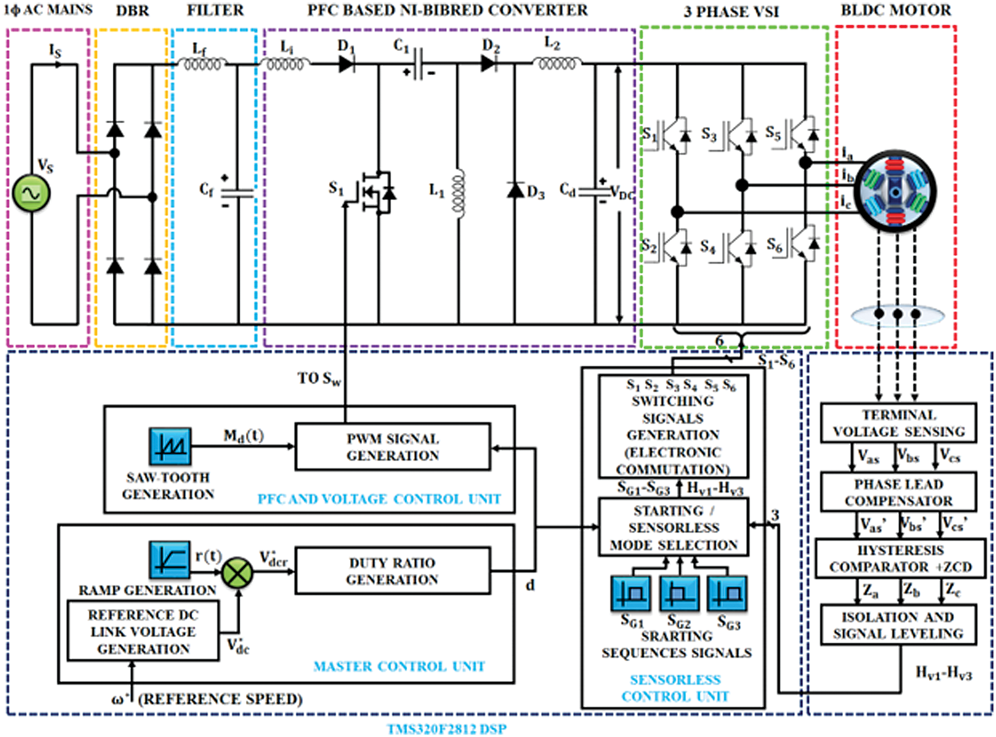
Figure 1: Circuit design of interleaved BIFRED converter for BLDCM drive
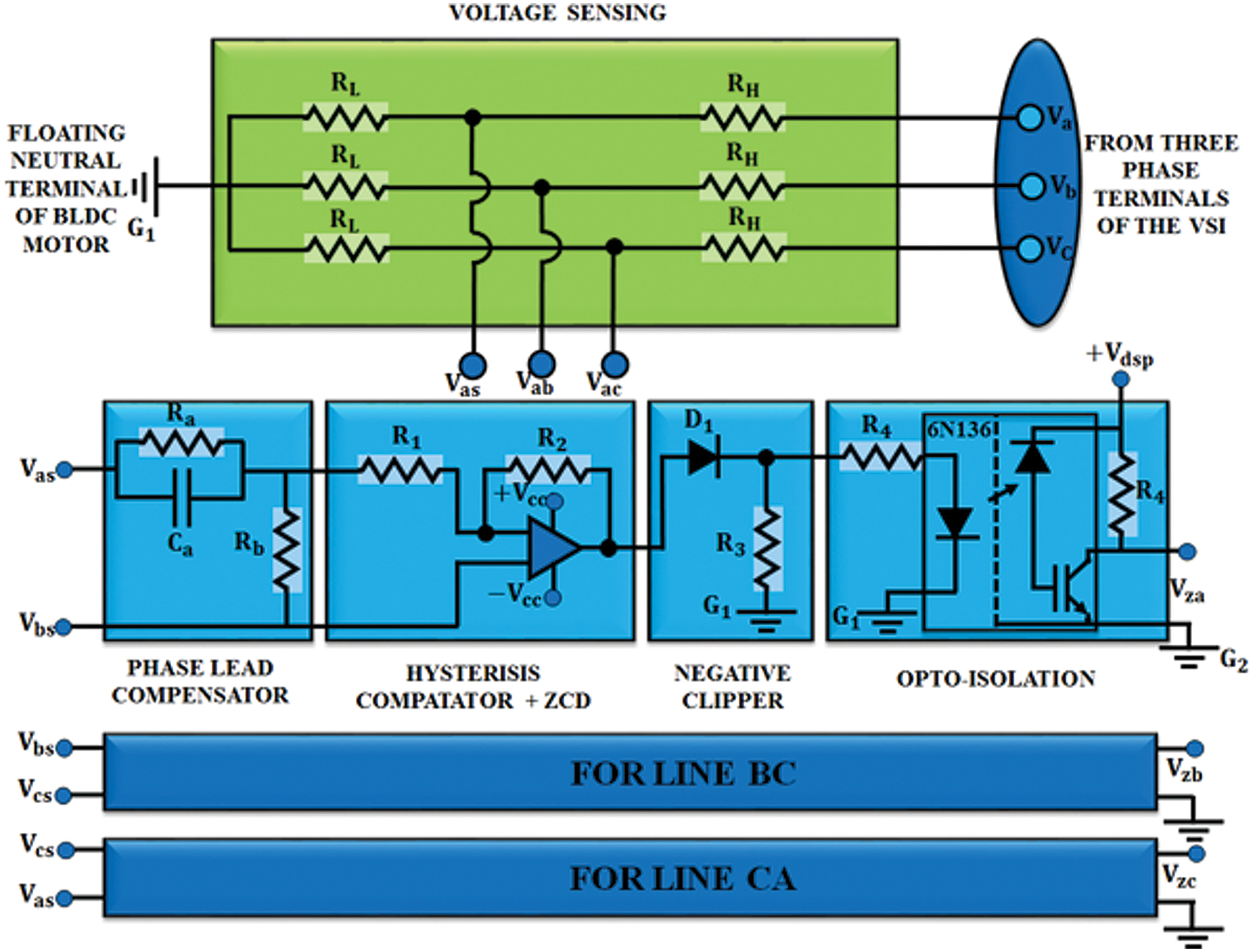
Figure 2: Generation of virtual hall signal circuit diagram
The components in the circuit design of virtual hall signal generation unit are described below. A resistive potentiometer gets the terminal voltage from the PMBLDCMD and it is used to step down the terminal voltage of BLDCM for keeping the similarity with the analogue Integrated Circuit. This step down potential is drawn to the phase lead compensator. Because of the hysteresis comparator and sensing circuit, the phase lag is eliminated in the virtual hall signal approximation. Then, the output of the lead phase is driven to the hysteresis comparator, in which the zero crossing detection (ZCD) is done to remove the commutation ripple. To neglect the error switching conditions, the range of hysteresis comparator is preferred as less phase change is achieved in allowed range. The negative half cycle is clipped from negative clipper, which is driven by output from comparator. It is connected to the opto-isolator, in which the isolation is optically done within the DSP and power signal condition circuit. Fig. 3 shows the graphs of the counter emf’s, with definite (HA-HC) hall signals and necessary hall signals.
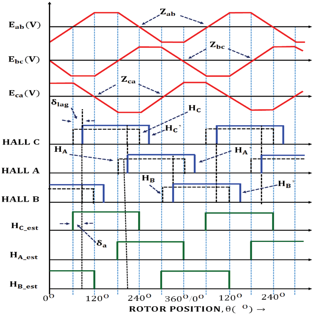
Figure 3: Output with compensation of line counter emf vs. actual and estimated hall signals
The BLDC motor is expressed by the
where, the resistance in the stator per phase is indicated by R which is implicit to be similar for all phases, the inductance in stator per phase is represented by L and the mutual inductance in between phases is denoted by M.
It is assumed that the self inductance of stator is non-aligned to the spot of the rotor. Thus,
The mutual inductances is represented as,
The phase resistances are considered to be same since the system is considered as phase balanced system. Therefore,
The formulae (4)–(6) indicate the mutual inductance. If it is neglected, the motor equations are rewritten as,
4 Design of Interleaved BIFRED Converter
The interleaved BIFRED converter works under triple discontinuous current period. Due to the switch, the current becomes discontinuous by the inductors. Five different processes are briefly explained in in the subsequent part.
Mode 1: At this stage, turn on the switch S1 and so the current passes from the source towards the inductor Li. The inductor L1 charges from the capacitor C1, since the capacitor C1 is discharged. The Cd gives the necessary energy to BLDCM drive. The inductor L2, diodes D2 and D3 are not conducting.
Mode 2: In this stage, turn off the switch so that current begins to decrease in inductor Li and L1. Because of this decrease, there is charging in the capacitor C1, inductor L2 and dc link condenser Cd. The voltages of capacitors and inductor get increased.
Mode 3: The inductor current is in discontinuous current mode because the inductor L2 becomes zero. The inductors Li and L2 keep on discharging whereas the capacitors C1 and Cd continues to charge. This happens in mode 3.
Mode 4: At this time, the middle capacitor C1 is still charging and the inductor L2 current become zero and comes to DICM again. Therefore, the BLDCM drive is powered by dc link condenser Cd. This operation is done in mode 4.
Mode 5: Here, the inductors Li, L1, L2 are fully drained and so the only source of BLDCM drive is dc link capacitor, which provides energy to the motor. Because of this, the voltage falls within dc link capacitor and it persists to decrease.
These are the five modes of operation on DICM of interleaved BIFRED converter. The inductors and capacitors are designed to make the BIFRED converter to operate in DCIM mode as PFC converter. Thus, for a 310 V 1HP PMBLDCM drive, the interleaved PFC based BIFRED converter is modified by using the following equations,
The supply voltage is derived from the equation shown below,
here,
Vm stands for peak input potential difference.
fL stands for Line frequency
Vin is said to be input average voltage
D represents the duty ratio
fs represents switching frequency, Iin represents average input current.
For the buck-boost converter specification, the potential difference in dc link is given by,
The input inductance Li and output inductance’s Loc critical value is given by,
The intermediate and the dc link capacitance are found out by using the following formulae,
where RL is known as equivalent emulated resistance.
The
Finally, the filter inductance calculated by using the expression,
5 Phase Lead Compensator Model
The delay in the phase or the balanced phase is minimized by the use of phase lead compensator before the operation of hysteresis comparator. Thus, measuring of phase delay in zero crossing between line counter emf and waves from hall sensor is done. Regarding the estimation, the phase-lead compensator is modeled as,
Two corner frequencies are represented by
The transfer function of the compensator with realized RC network is given by the following equation,
The bode plot has been plotted to get the desired frequency by using the required phase delay in the phase-lead compensator. By using this, the designed compensator has an error less than 0.5%. The phase lead compensator is calculated and the governing of projected motor drive is described in the subsequent part.
The major functions of BLDCM drive are to correct the power factor and to reduce the THD by eliminating voltage ripples by using the sensorless control.
The rotor’s velocity in BLDCM is related directly to the dc link potential difference. By knowing the velocity, the reference voltage has been generated. The generated reference potential difference in dc link side is expressed as,
where, Kv represents the voltage constant of BLDCM drive. From the above equation, the potential difference in dc link is calculated. The generated duty ratio is specified into the PFC control, sensorless control and voltage control to gain the sensorless work. The ramp signal is multiplied with the potential difference in dc link, which steadily increases the reference potential difference. When the motor starts to rotate, it gives enough time for the position of rotor alignment.
The switch in the PFC converter is triggered and the wave with PWM (Pulse Width Modulation) is set to the PFC converter to continue the chosen potential difference with DC bus side. From the master control, the preferred duty ratio is attained. By this, the power factor correction is done on the main supply without the alteration in current sensing equipment or voltage sensing equipment.
The pulses from the switching signals are given to the VSI to operate the BLDCM and to identify the rotor position. The virtual hall signals are found out by using these sensorless signals. This mode is used by various selection modes such as synchronization, sensorless mode and sensorless starting. By holding the current state, the switching state gets varied. The commutation failure is overcome by synchronizing the pulses with the other blocks. Three types are explained in the following part. At first, the position of the rotor alignment, turning on the two switches at VSI are assessed. The pulse is given to the motor to initially assign the rotor position. This is done to verify the position of the rotor to operate in sensorless mode. The six switch pulses in VSI are given sequentially with low frequency, which ranges from 10–15 Hz since the voltage at dc link side is directly related. The current in the stator side is produced when the dc link potential difference is high. To overcome this criteria, the machine begins with less speed and low frequency range in the initial stage. Later, the speed is increased. Finally, the desirable counter electromotive force is produced by the calculation of virtual hall waves. By using the above signal from the counter electromotive force detection circuitry, the motor is electronically commutated.
6 Simulation and Hardware Results
The interleaved BIFRED converter for BLDCM drive is analyzed and the simulation result of BLDCM drive with interleaved BIFRED converter is discussed in the subsequent section. Here, the power factor correction is done. The voltage ripples and harmonics are reduced, which leads to the reduction in the THD value.
The source current and voltage are found to be sinusoidal in nature as these are not affected by the motor drive load. The amplitude of input potential is 220 V and current amplitude is 1.5 A.
The proposed converter is designed to meet the power factor specification as mentioned in the description. Fig. 4 indicates the input ac source current with the power factor correction converter. It is a single phase sinusoidal waveform with 1.5 A current. Fig. 5 describes the AC source voltage with 210 V. Its corresponding hardware results are depicted in Fig. 6.
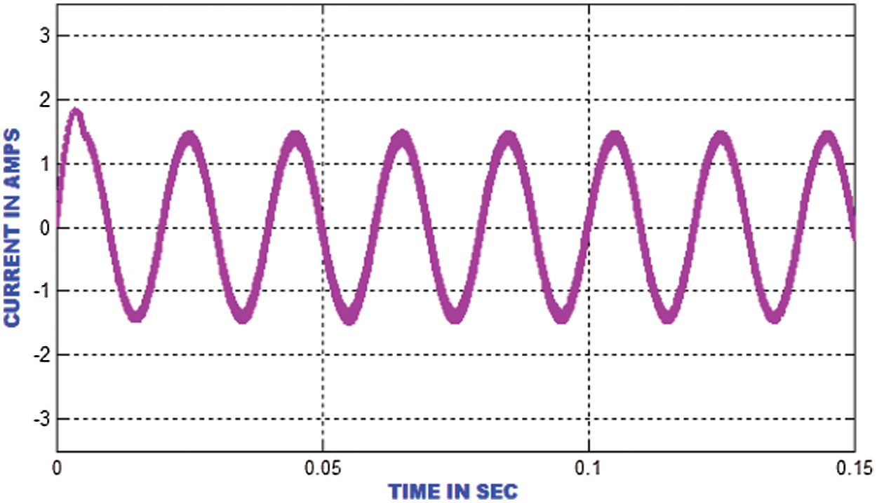
Figure 4: Input AC source current waveform with AC-DC PFC converter
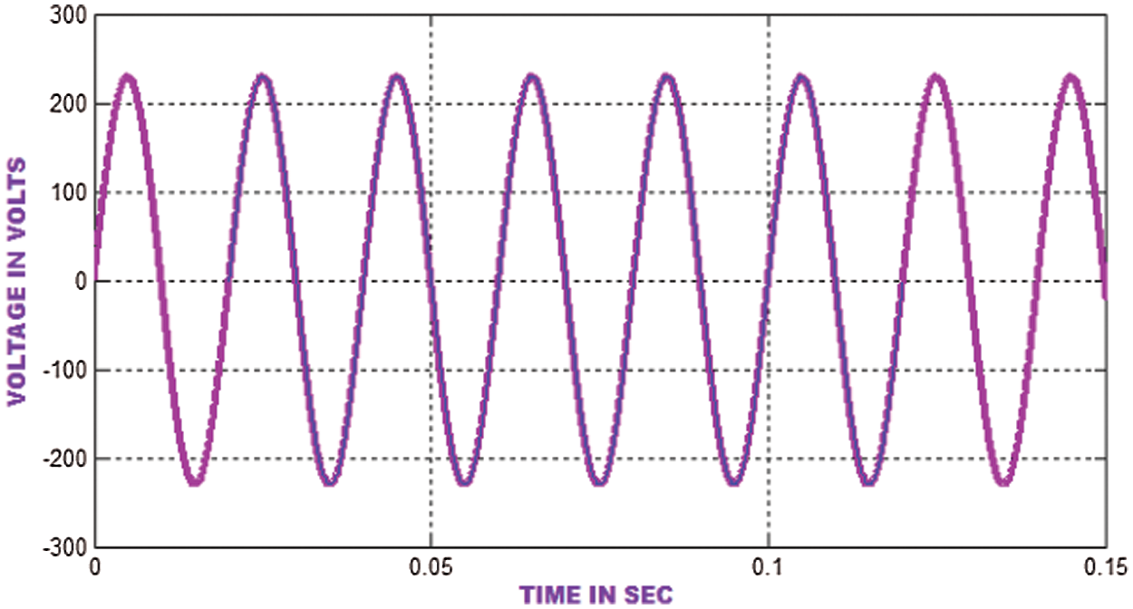
Figure 5: Waveform of input AC source voltage
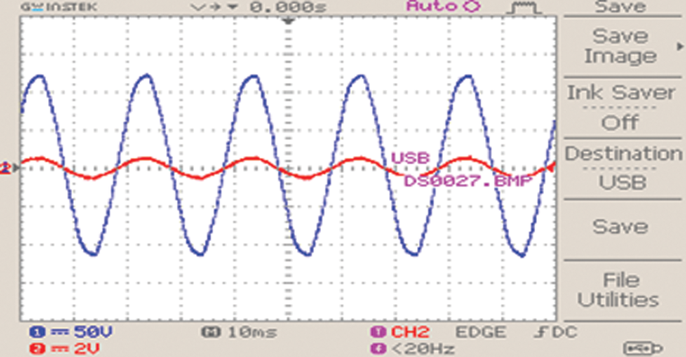
Figure 6: Hardware results of input voltage and current waveform
The BLDCM current for the described model is 3 A and the current settles at 0.1 s, which is graphed in Fig. 7.
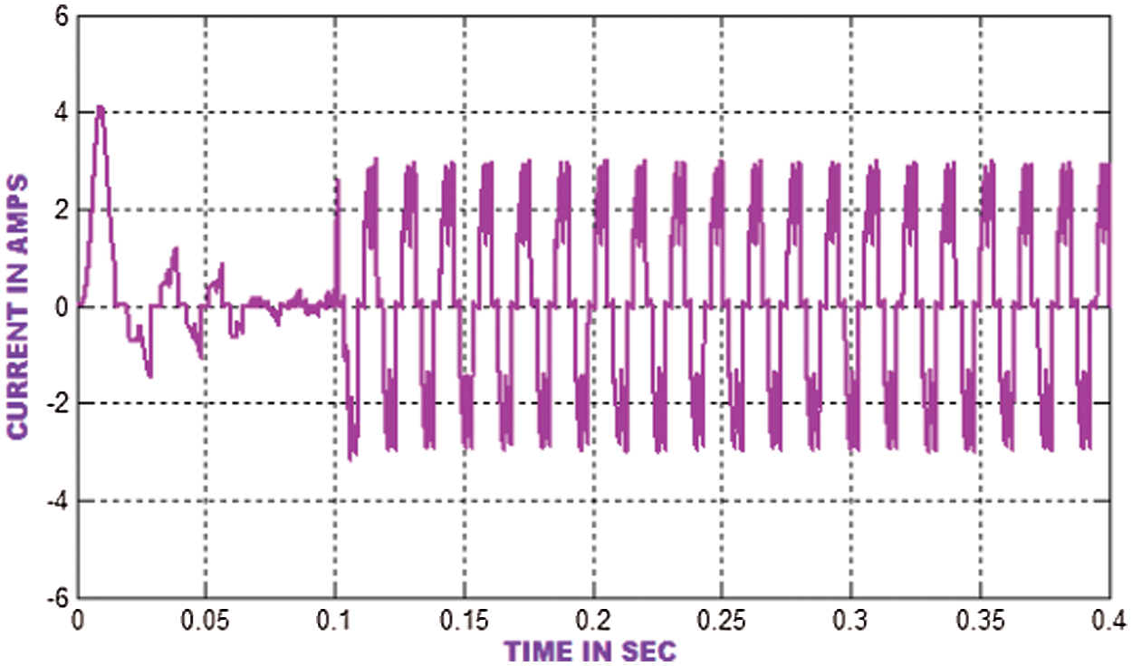
Figure 7: BLDC motor current output
The PMBLDCMD current waveform is plotted in Fig. 8 whereas the torque waveform is depicted in Fig. 9 and the torque waveform settles at 0.1s. The hardware outcomes of the PMBLDCMD torque waveform is represented in Fig. 10.

Figure 8: Hardware results of BLDC motor current waveform
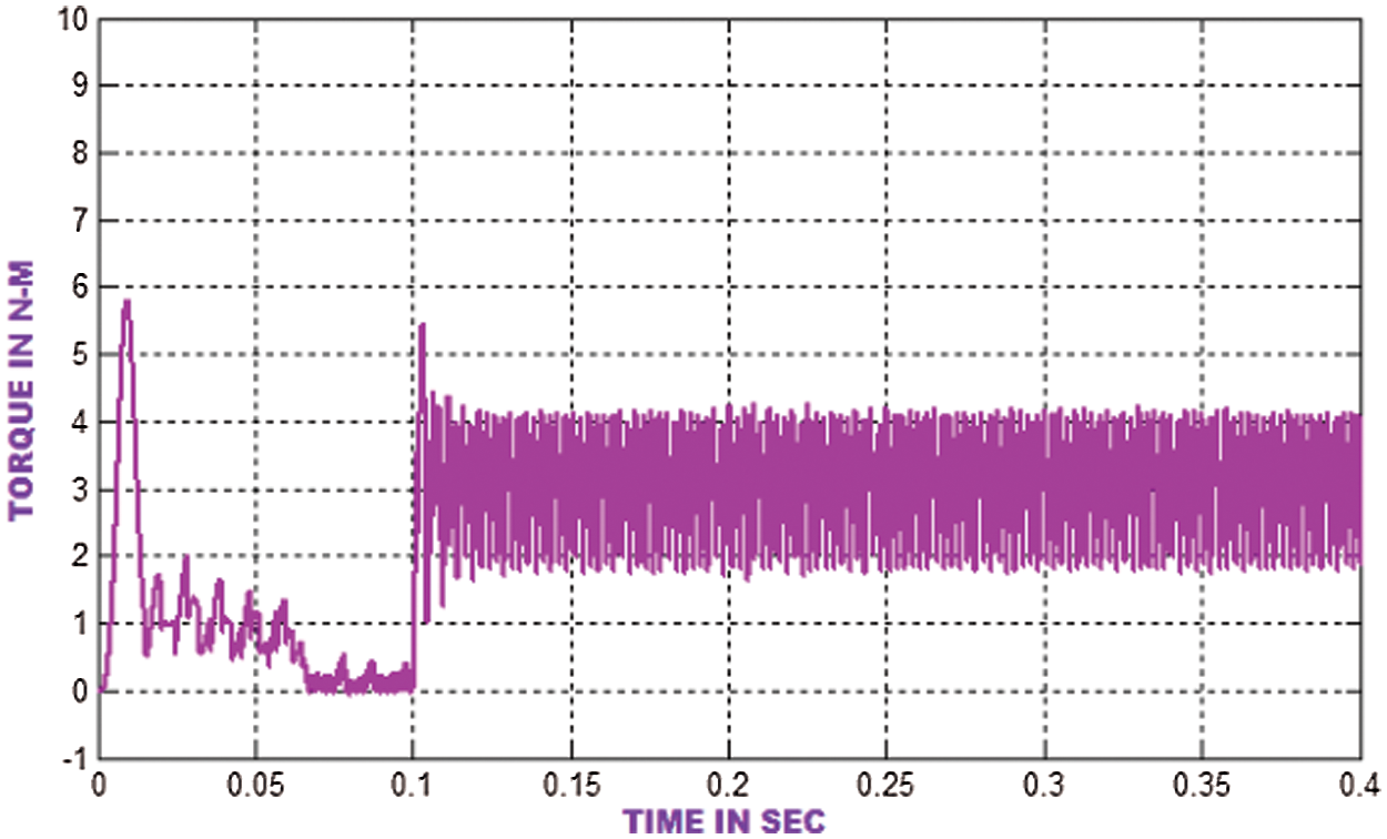
Figure 9: BLDC motor torque waveform
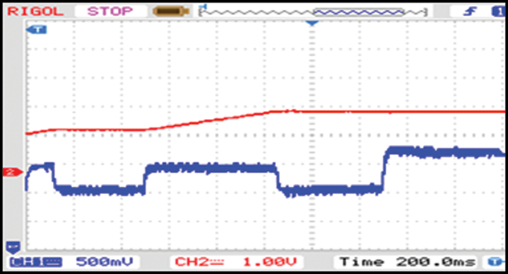
Figure 10: Hardware results of Brushless DC motor torque waveform
The output potential difference graph of the motor with PI controller is plotted in Fig. 11. Here, the accuracy is high and the peak is less than 0.01 s. The waveform settles with 200 V at 0.04 s.
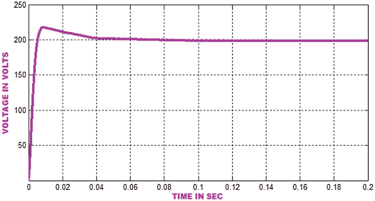
Figure 11: AC-DC PFC converter output voltage waveform with PI controller (Ref. Voltage = 200 V)
Fig. 12 signifies the hardware outcomes of AC-DC PFC Converter output voltage waveform using PI controller.
Figure 12: Hardware results of AC-DC PFC converter output voltage waveform with PI controller (Ref. Voltage = 200 V)
The Brushless DC motor speed is plotted in Fig. 13. The preferred speed is set as 1000 rpm. The rotor speed settles at 0.1 s. Here, the PI controller is employed to regulate the motor speed. The hardware outcomes of Speed in BLDCM using PI controller is highlighted in Fig. 14.
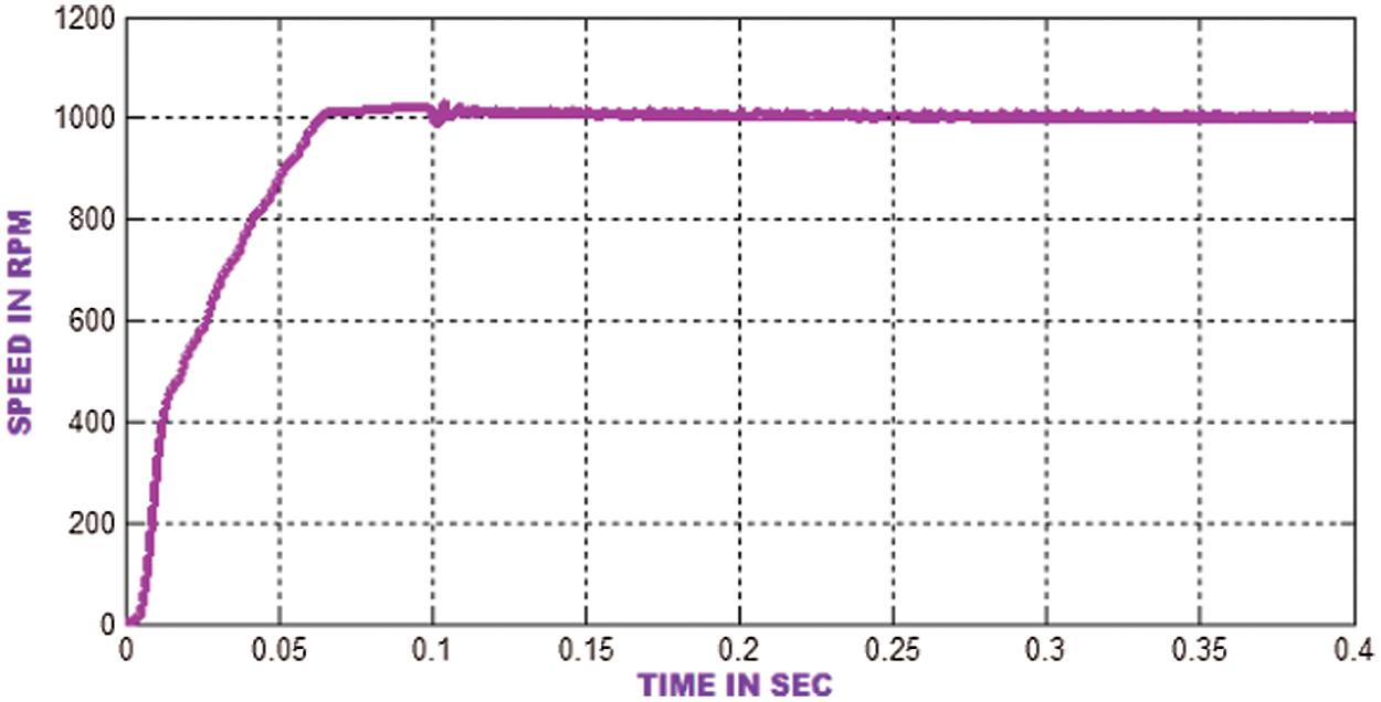
Figure 13: Speed waveform using PI controller in BLDCM (Ref. Speed = 1000 rpm)
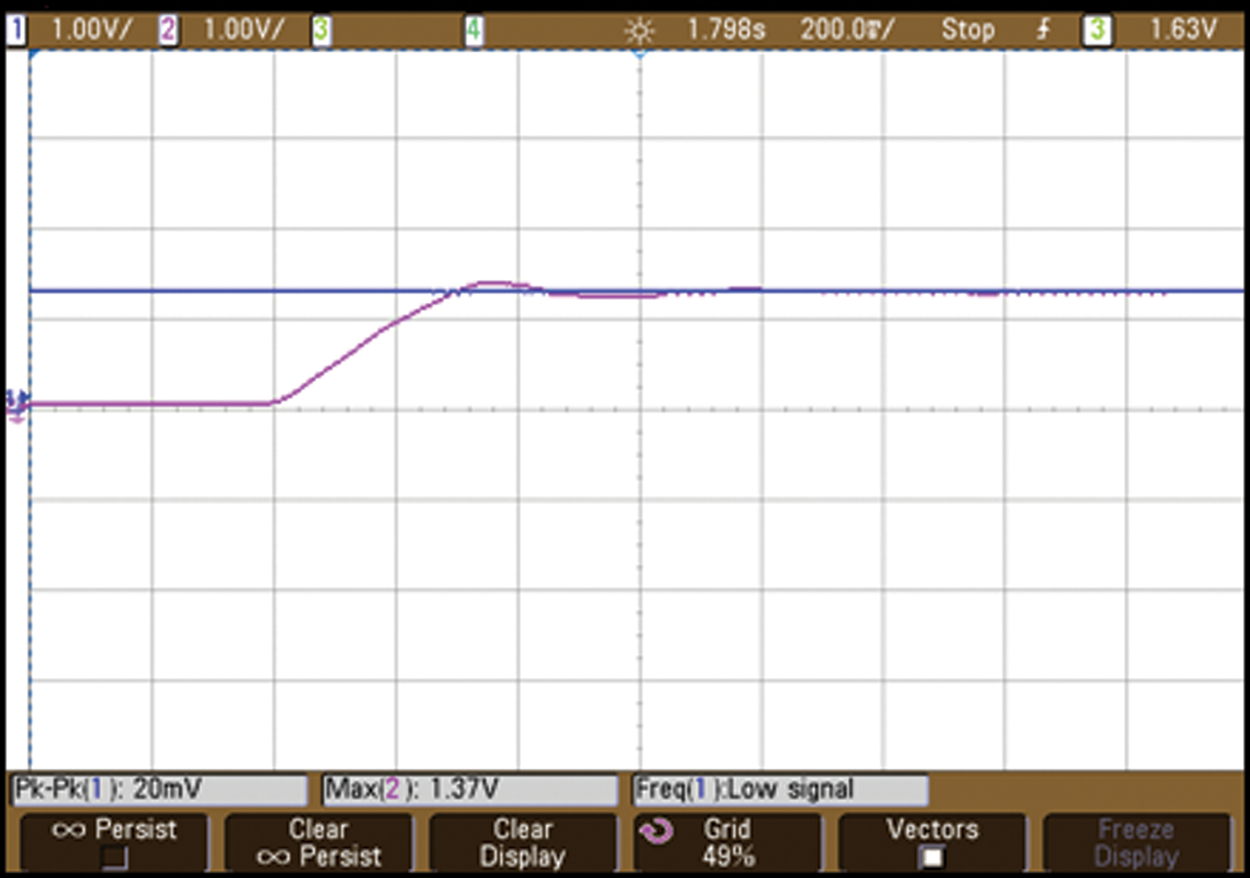
Figure 14: Hardware results of speed waveform using PI controller in BLDCM (Ref. Speed = 1000 rpm)
The device’s THD level is less than 2% and the PF is maintained as 1. The THD level is represented in Fig. 15.
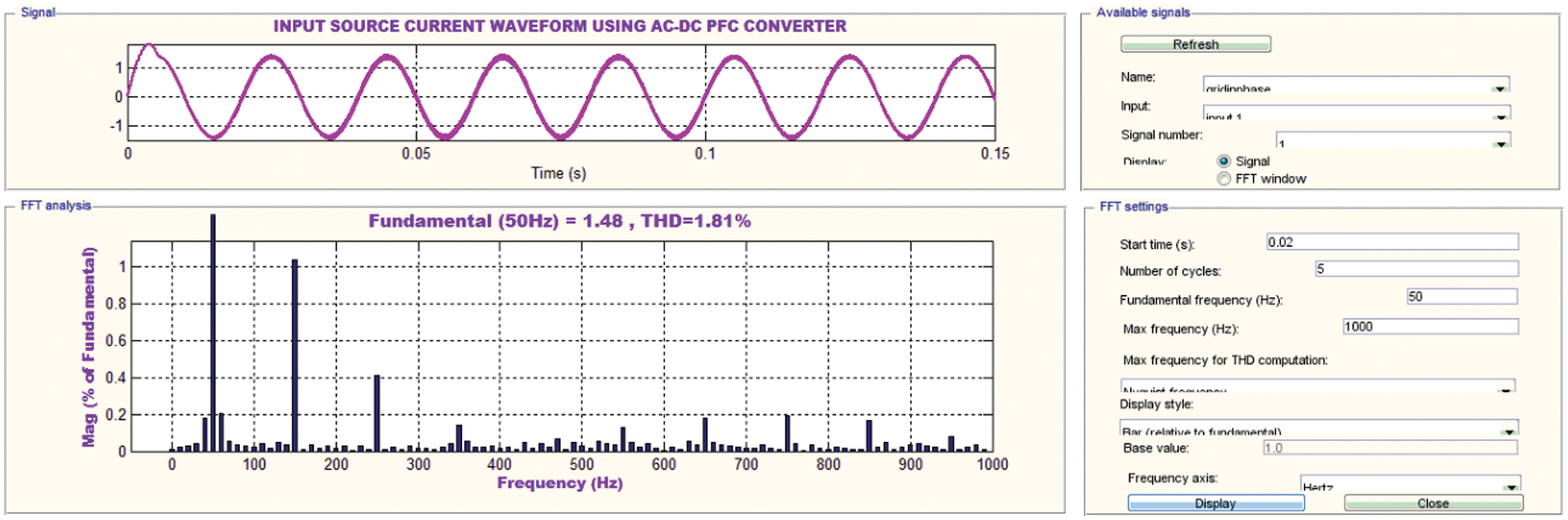
Figure 15: Harmonic spectra of Input source current waveform using AC-DC PFC converter
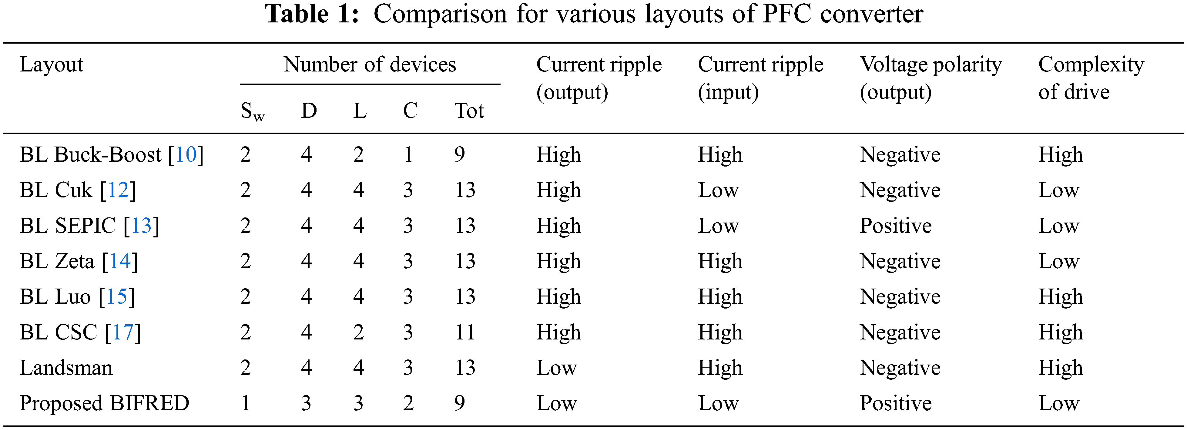
The comparison of the proposed converter in consideration with the factors like number of components, current ripples, voltage polarity and drive complexity is shown in Tab. 1. It indicates that the suggested converter outperforms the existing converters.
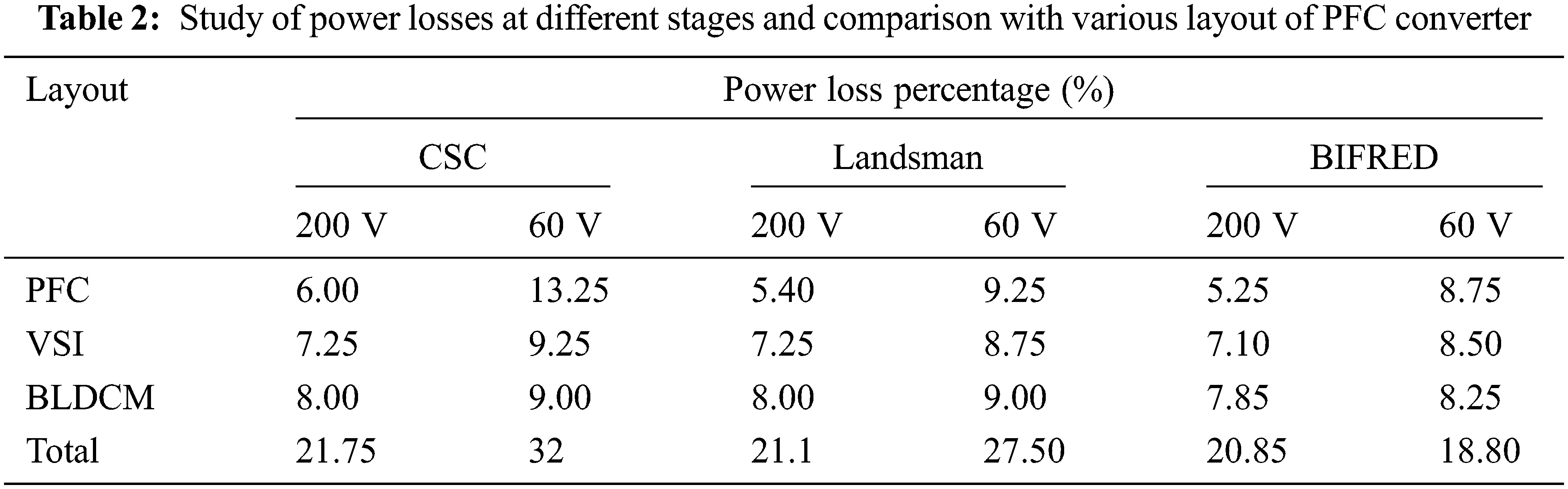
The amount of power loss for different converter with different operations such as PFC, VSI and BLDC is given in Tab. 2.
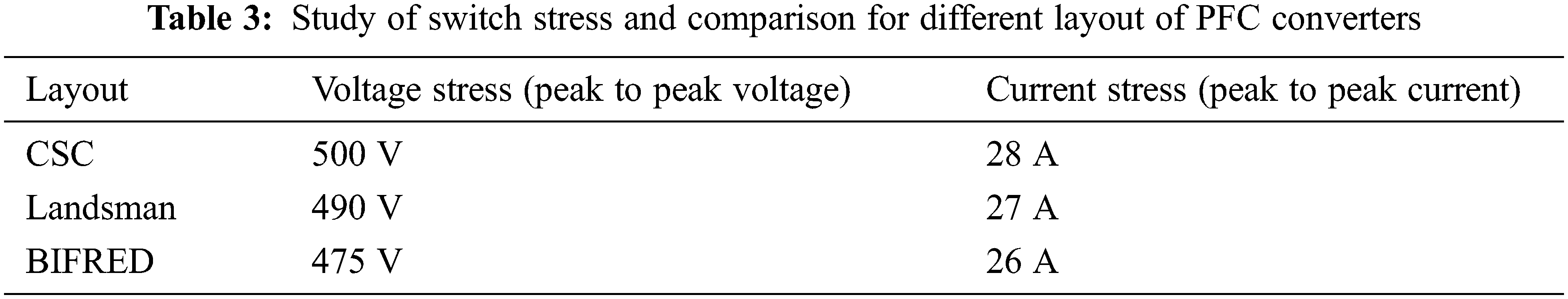
The entire work is experimentally investigated as illustrated in Fig. 16. The comparison of peak-to-peak voltage and current stresses is given in Tab. 3, which depicts that the proposed converter has less stress than other converters.
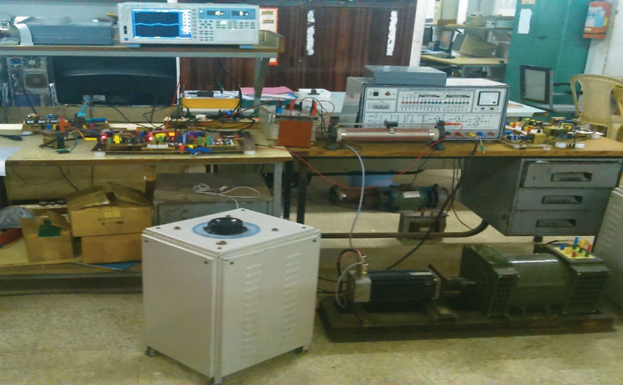
Figure 16: Experimental setup for proposed system
The interleaved BIFRED converter for BLDCMD with PFC is designed and analyzed in this study. This is done with Simulink assistance and the simulation outcomes are discussed with prior validations. Here, the PFC converter is used to maintain the unity power factor. The voltage ripples and harmonics are eliminated to decrease the THD level. The usage of sensorless BLDCM drive makes the cost of hardware system effective. In addition, the maintenance and complexity of the motor are reduced with the assistance of virtual hall signal production. In future, the PFC converter is possibly done with DTC (Direct Torque Control) sensorless mode for high power usages.
Funding Statement: The authors received no specific funding for this study.
Conflicts of Interest: The authors declare that they have no conflicts of interest to report regarding the present study.
1. T. Yazdan, W. Zhao, T. A. Lipo and B. I. Kwon, “A novel technique for two-phase BLDC motor to avoid demagnetization,” IEEE Transactions on Magnetics, vol. 52, no. 7, pp. 1–4, 2016. [Google Scholar]
2. H. S. Athab and D. D. C. Lu, “A high-efficiency AC/DC converter with quasi-active power factor correction,” IEEE Transactions on Power Electronics, vol. 25, no. 5, pp. 1103–1109, 2019. [Google Scholar]
3. H. J. Chiu, Y. K. Lo, H. C. Lee, S. J. Cheng and Y. C. Yan, “A Single-stage soft-switching flyback converter for power-factor-correction applications,” IEEE Transactions on Industrial Electronics, vol. 57, no. 6, pp. 2187–2190, 2019. [Google Scholar]
4. W. Na, T. Park, T. Kim and S. Kwak, “Light fuel-cell hybrid electric vechicles based on predictive controllers,” IEEE Transactions on Vehicular Technology, vol. 60, no. 1, pp. 89–97, 2021. [Google Scholar]
5. M. Fazil and K. R. Rajagopal, “A novel air-gap profile of single phase permanent magnet brushless DC motor for starting torque improvement and cogging torque reduction,” IEEE Transactions on Magnetics, vol. 46, no. 11, pp. 3928–3932, 2018. [Google Scholar]
6. R. K. Pongiannan, S. Paramasivam and N. Yadaiah, “Dynamically reconfigurable PWM controller for three-phase voltage-source inverters,” IEEE Transactions on Power Electronics, vol. 26, no. 6, pp. 1790–1799, 2020. [Google Scholar]
7. J. K. Park and J. Hur, “Detection of inter-turn and dynamic eccentricity faults using stator current frequency pattern in IPM-type BLDC motors,” IEEE Transactions on Industrial Electronics, vol. 63, no. 3, pp. 1771–1780, 2017. [Google Scholar]
8. M. Bertoluzzo, G. Buja, R. K. Keshri and R. Menis, “Sinusoidal versus square-wave current supply of PM brushless DC drives: A convenience analysis,” IEEE Transactions on Industrial Electronics, vol. 62, no. 12, pp. 7339–7349, 2017. [Google Scholar]
9. J. Sha, J. Xu, S. Zhong, S. Liu and L. Xu, “Control pulse combination-based analysis of pulse train controlled DCM switching DC–DC converters,” IEEE Transactions on Industrial Electronics, vol. 62, no. 1, pp. 246–255, 2019. [Google Scholar]
10. B. Poorali and E. Adib, “Analysis of the integrated SEPIC-flyback converter as a single-stage single-switch power-factor-correction LED driver,” IEEE Transactions on Industrial Electronics, vol. 63, no. 6, pp. 3562–3570, 2016. [Google Scholar]
11. S. Singh, B. Singh, G. Bhuvaneshwari and V. Bist, “Power factor corrected zeta converter based improved power quality switched mode power supply,” IEEE Transactions on Industrial Electronics, vol. 62, no. 9, pp. 5422–5433, 2015. [Google Scholar]
12. W. Lu, S. Lang, L. Zhou, H. H. C. Lu and T. Fernando, “Improvement of stability and power factor in PCM controlled boost PFC converter with hybrid dynamic compensation,” IEEE Transactions on Circuits and Systems I: Regular Papers, vol. 62, no. 1, pp. 320–328, 2020. [Google Scholar]
13. X. Liu, J. Xu, Z. Chen and N. Wang, “Single-inductor dual-output buck–boost power factor correction converter,” IEEE Transactions on Industrial Electronics, vol. 62, no. 2, pp. 943–952, 2018. [Google Scholar]
14. X. Zhou, X. Chen, M. Lu and F. Zeng, “Rapid self-compensation method of commutation phase error for low- inductance BLDC motor,” IEEE Transactions on Industrial Informatics, vol. 13, no. 4, pp. 1833–1842, 2017. [Google Scholar]
15. S. Sashidar, V. G. P. Reddy and B. G. Fernandes, “A single-stage sensorless control of a PV-based bore-well submersible BLDC motor,” IEEE Journal of Emerging and Selected Topics in Power Electronics, vol. 7, no. 2, pp. 1173–1180, 2018. [Google Scholar]
16. B. Singh, S. Singh, A. Chandra and K. Al-Haddad, “Comprehensive study of single-phase AC-DC power factor corrected converters with high-frequency isolation,” IEEE Transactions on Industrial Informatics, vol. 7, no. 4, pp. 540–556, 2017. [Google Scholar]
17. V. Bist and B. Singh, “An adjustable-speed PFC bridgeless buck–boost converter-fed BLDC motor drive,” IEEE Transactions on Industrial Electronics, vol. 61, no. 6, pp. 2665–2677, 2016. [Google Scholar]
18. V. Bist and B. Singh, “A PFC-based BLDC motor drive using a canonical switching cell converter,” IEEE Transactions on Industrial Informatics, vol. 10, no. 2, pp. 1207–1215, 2018. [Google Scholar]
19. P. Damodharan and K. Vasudevan, “Sensorless brushless DC motor drive based on the zero-crossing detection of back electromotive force (EMF) from the line voltage difference,” IEEE Transactions on Energy Conversion, vol. 25, no. 3, pp. 661–668, 2018. [Google Scholar]
20. L. I. Iepure, I. Boldea and F. Blaabjerg, “Hybrid I-f Starting and observer-based sensorless control of single-phase BLDC-PM motor drives,” IEEE Transactions on Industrial Electronics, vol. 59, no. 9, pp. 3436–3444, 2019. [Google Scholar]
21. T. W. Chun, Q. V. Tran, H. H. Lee and H. G. Kim, “Sensorless control of BLDC motor drive for an automotive fuel pump using a hysteresis comparator,” IEEE Transactions on Power Electronics, vol. 29, no. 3, pp. 1382–1391, 2020. [Google Scholar]
22. H. Lu, L. Zhang and W. Qu, “A new torque control method for torque ripple minimization of BLDC motors with un-ideal back EMF,” IEEE Transactions on Power Electronics, vol. 23, no. 2, pp. 950–958, 2018. [Google Scholar]
23. J. S. Park, K. D. Lee, S. G. Lee and W. H. Kim, “Unbalanced ZCP compensation method for position sensorless BLDC motor,” IEEE Transactions on Power Electronics, vol. 34, no. 4, pp. 3020–3024, 2018. [Google Scholar]
24. F. Aghili, “Fault-tolerant torque control of BLDC motors,” IEEE Transactions on Power Electronics, vol. 26, no. 2, pp. 355–363, 2020. [Google Scholar]
25. H. Choi, “Interleaved boundary conduction mode (BCM) buck power factor correction (PFC) converter,” IEEE Transactions on Power Electronics, vol. 28, no. 6, pp. 2629–2634, 2020. [Google Scholar]
 | This work is licensed under a Creative Commons Attribution 4.0 International License, which permits unrestricted use, distribution, and reproduction in any medium, provided the original work is properly cited. |