DOI:10.32604/iasc.2022.023058
| Intelligent Automation & Soft Computing DOI:10.32604/iasc.2022.023058 | |
| Article |
Improving the Efficiency of HEV Electronic Applications Using CAN-BUS Communication
Department of Electrical and Electronics Engineering, St. Xaviers Catholic College of Engineering, Chunkankadai, 629003, Tamil Nadu, India
*Corresponding Author: A. George Ansfer. Email: georgeansfera123@gmail.com
Received: 26 August 2021; Accepted: 08 December 2021
Abstract: A new energy management technique with aid of Controller Area Network (CAN) bus for hybrid electric vehicle (HEV) is proposed in this research. HEV is a type of hybrid vehicle that combines with an electric propulsion system a conventional internal combustion engine system. The electric powertrain operation is intended to achieve greater fuel economy than a conventional vehicle. To accurately distribute power from one of the battery sources, the Energy Management System determines the reference speed for the electric motor drive and the internal combustion engine. The Proportional and Integral (PI) controller is used to maximize the gain of the primary and secondary controllers for maximum overshoot and resolution time. By optimizing the value, using the Naked Mole Rat optimization technique, the efficiency is improved. The CAN bus is a multi-master communication protocol characterized by the deterministic resolution, high efficiency and simple implementation. We introduce a secure technology that helps to automotive CAN protocol which is often used in HEV networks. The simulation results show that the proposed approach achieves an increased efficiency of 97%.
Keywords: Hybrid electric vehicle simulation; electric vehicle; batteries; controllers; CAN-bus communication; naked mole rat optimizations
Current hybrid electric vehicles (HEVs) use performance-enhancing innovations, for example, regenerative brakes that convert the vehicle's kinetic energy into electrical energy, which is stored in a battery. As of April 2020, more than 17 million hybrid electric vehicles (HEVs) have been sold worldwide since their launch in 1997. Japan has the world's largest Hybrid Electric Vehicle (HEV) fleet with 7.5 million hybrids registered as of March 2018. The commercial hybrid vehicle is one that uses two or more distinct types of power, such as submarines that use diesel when surfaced and batteries when submerged. Other means to store energy include pressurized fluid in hydraulic hybrids [1]. CAN is a protocol that was developed by Robert Bosch in around 1986. Initially, it was mainly designed for communication with in the Hybrid Electric Vehicles. It is now used in many other contexts, Like UDS (Unified Diagnostic Services) and KWP (Kilo Watts-Peak) 2000, CAN also be used for the on-board diagnostics.
Desai (2009) et al. [2] have proposed the comparative study of Hybrid Electric Vehicles (HEV) control strategies for better analysis of drivetrain performance. Hybrid Electric Vehicles (HEV) control strategies results suggest that improved drivetrain efficiency analysis is above 70% of State of Charge (SOC). Krishna Buddhi (2010) have proposed the plug-in is an alternative method to improve the performance of hybrid electric vehicles (HEVs). The purpose of this study is to propose a method to increase the efficiency of current range extension technology by utilizing energy from exhaust gases. The efficiency of the compressor assumed to be 74%. The initial power gain ranged from 9.35% at 1920 rpm to 18.12% at 3907 rpm [3].
Jianqiang Kang (2011) has been proposed the energy efficiency of the Ni-MH (Nickel-metal hydride) battery used in hybrid electric vehicles (HEV). The energy efficiency of a Ni-MH battery (40Ah) was tested. A test stand was established to test the energy efficiency of the Ni-MH battery [4]. Theoretical analysis and test results show that the charge and discharge capacity of Ni-MH batteries within the 30%–80% state of charge (SOC) range is more than 90%, which provides a theoretical basis for battery selection and dynamic upgrade technology for hybrid electric vehicle (HEV) systems, controlling strategy [5].
Osama et al. (2012) have proposed the power-split design characterized by internal energy recycling, which can occur in a closed loop at a certain velocity ratio, leading to significant power losses [6]. Saiful Sulkifli et al. (2013) proposed the influence of motor size and performance on the acceleration and emission of split-parallel hybrid electric vehicle (HEV). The motor performance level is 30%, 50%, and 92% and the amount to obtain operation with full-increase motor efficiency [7].
Zhang et al. (2014) have proposed, on the other hand, a single-motor hybrid electric vehicle (HEV) with an automatic manual transmission (AMT) and a wet clutch that compromises configuration cost and complex issues and is widely used in commercial vehicles [8]. Payri et al. (2014) have proposed an operating system that analyses power demands based on current operating conditions and estimates of future driving conditions and proposes energy management to reduce the fuel consumption of a hybrid electric vehicle (HEV) [9]. QI Yunlong (2015) proposed a neural network and performance-based control for the dual-mode hybrid electric vehicle (HEV). The engine efficiency remains basically unchanged but the transmission efficiency increased by 4% from 92%–96%, while the corresponding vehicle efficiency increases by 1.4% [10,11].
Kalangadan (2015) has been proposed the Proportional Integral Derivative Controller (PID) has been generally used for most industrial process, due to its simplicity and effectiveness in control. This type of controller is commonly used in level, flow, temperature and vehicular system, as well as electric motors [12]. In addition, the design of the Proportional Integral Derivative Controller (PID) controller is considered easy to implement, since it is necessary to tune three parameters Kp, Ki and Kd and tuning methods can be performed automatically [13].
Montazeri-Gh et al. (2015) have been proposed the energy management controller with multi-input fuzzy logic has been developed to improve the fuel economy of a power-split Hybrid Electric Vehicle (HEV) in a configuration similar to the Toyota Prius [14]. Chen et al. (2015) have been proposed an optimal Energy Management System (EMS) for engine/motor Hybrid Electric Vehicle (HEV) was developed by using improved Particle Swarm Optimization (PSO) [15]. Saikyo et al. (2015) have been proposed a sequential approximate optimization approach using radial basis function network has been adopted to optimize the torque control for parallel Hybrid Electric Vehicle (HEV). Lee et al. (2015) have been proposed a recent paper, a control algorithm using dynamic programming has been proposed for optimizing fuel consumption of series Hybrid Electric Vehicle (HEV) at typical driving modes [16].
Mulia Pratama et al. (2015) have been proposed the design of CAN-bus for research applications purpose Hybrid Electric Vehicle (HEV) using the Advance RISC Machine (ARM) microcontroller. CAN is a message-based protocol, designed specifically for automotive applications but now also used in other areas such as industrial automation and medical equipment [17]. The disadvantages of master control are need more cable, because every electronic part must connect to master control. Vineet Kumar et al. (2016) have been proposed the speed control of Hybrid Electric Vehicle (HEV) using Fractional Order Fuzzy Proportional-Integral (PI) and Proportional-Deferential (PD) controllers [18].
Sasmita Padhy (2017) have proposed the system of speed increase, the study is further extended for different controllers like PI, PID, and PI-PD controller and the superiority of Proportional Integral-Proportional Differential (PI-PD) controller over conventional controllers is demonstrated. Proportional Integral (PI) controller is one of the approaches which can be used to improve the performance of the system [19]. At that point PEVs are thought of and a PI-PD controller is proposed. The controller parameters are tuned employing proposed hSFS-PS technique [20]. Gargi Pancholi et al. (2017) have been proposed the system of comparative analysis of Hybrid Electric Vehicle (HEV) fed through PI controller of DC-DC converter and the operated with battery. The result of this system is being compared with only battery and ultra-capacitor [21].
The paper is organised as follows: Section 1, discussed a presentation of the Hybrid Electric Vehicle (HEV); Proportional-Integral (PI) and Proportional-Integral - Derivative (PID) controller; and expanded efficiency rates further. Section 2, present the HEV dynamics model and the proposed system using an optimisation of Naked Mole Rat (NMR). Section 3, describes a mathematical model of HEV powertrain and the efficiency model can be discussed. Section 4, discussed about analyse of result and the simulation output. This paper concludes with the last Section 5.
The power train integrates an engine, an electric subsystem, Planetary Gear subsystem, an automatic clutch, and an automatic/manual transmission system. This structure provides the regenerative braking during deceleration and enables effective operation of the motor assist. In order to provide a pure electrical propulsion, the automatic vehicle can disconnect the internal combustion engines (ICE) from the powertrain.
The proposed system block diagram Hybrid Electric Vehicle (HEV) power train consists of Energy Management subsystem, Electrical Subsystem, Internal Combustion Engine, Planetary Gear Subsystem and Vehicle dynamics. The reference input signal is indirectly controlling the engine speed. The electrical subsystem are including with battery and DC/DC converter. The converter is flowing through which Motor and Generator drives, the Motor drive (50 kw) is connected with Permanent Magnet Synchronous Motor (PMSM) motor drive and the generator drive (30 kw) is connected with Permanent Magnet Synchronous Motor (PMSM) generator drive. The Energy Management System (EMS) including with Hybrid Management System of flowing through the ICE speed controller. Hybrid Vehicle dynamic determines the car speed (km/h) and the road angle. Fig. 1 shows the proposed system block diagram.

Figure 1: Block diagram of proposed system
The Electrical Subsystem consists of four parts: the electrical motor, the generator, the battery, and the converter DC/DC.
The electric motor is a Permanent Magnet Synchronous Engine (PMSM) with the associated drive, 500 Vdc, 50 KW interior. This electric motor [22] has 8 poles, and it buries the magnets. To achieve a maximum motor speed of 6000 rpm a flux weakening vector control is used. The generator is a Permanent Magnet Synchronous Motor (PMSM) with the associated drive, 500 Vdc, 2 poles, 30 KW. To achieve a maximum motor speed of 13000 rpm, a vector control is employed. The battery is a 6.5 Ah, 200 Vdc, 21 kW Nickel-Metal-Hydride battery (Ni-MH). The voltage is regulated by the DC/DC Converter (boost). The DC/DC converter adapts the [23] battery low voltage (200 V) to the DC bus that feeds the AC motor at a 500 V voltage.
The Planetary Gear Subsystem models the power spilt device. It uses a planetary device, which transmits the mechanical motive force from the engine, the motor and the generator by allocating and combining them.
2.3 Internal Combustion Engine
The Internal Combustion Engine subsystem models a gasoline fuel engine [24] with speed governor of 57 KW @ 6000 rpm. The throttle input signal is between zero and one, and specifies the torque that the engine requires as a fraction of the maximum torque [25] possible.
2.4 Energy Management Subsystem Model
The Energy Management Subsystem (EMS) determines reference signals for the electric motor driver, electric generator driver and internal combustion engine (ICE) to accurately distribute power [26] from these three sources.
2.5 Vehicle Dynamics Subsystem
The vehicle dynamic subsystem models all the mechanical parts of the vehicle.
• Signal reduction reduces the speed of the gear motor and increases torque.
• The difference in divides the input torque wheels into two equal torques.
• Tire dynamics refers to the force applied to the ground.
• Automotive dynamics refers to kinetic [27] influence in the overall system.
• Models make up for all the losses of the viscous friction mechanical system.
The small perturbation based the vehicle Dynamic architecture mode of installed with Hybrid Electric Vehicle (HEV) powertrain as shown in Fig. 2,

Figure 2: Vehicle dynamic architecture
The Vehicle Dynamic Architecture based on the Hybrid Electric Vehicle (HEV) powertrain consists of Integrated Starter Alternator (ISA), Diesel Engine (ICE), Inverters, switchbox, Battery (Ni-MH) and Traction motor and gearbox (EM). The hybrid electric vehicle (HEV) is powered by an internal combustion engine (ICE) and an electric motor/generator (EM) in series or parallel configuration. The internal combustion engine (ICE) provides the vehicle with an extended driving range, while the electric motor (EM) increases performance and fuel economy. Many hybrid electric vehicle (HEV) projects have improved fuel economy by 20% to 40%. Therefore, the hybrid electric vehicle (HEV) offers a good solution to overcome the energy shortage as shown in Fig. 2. The design and control of such powertrains includes intelligent control mechanisms and modelling and simulation of power management techniques aimed at improving the operating parameters for any driving position. The internal combustion engine (ICE) engine output is first converted into electricity using a generator.
The hybrid electric vehicle powertrain design process is powered by modelling and simulation. A Proportional Integration (PI) - Led controller is a proportional gain equal to one coordinator; Connected in series with a lead controller as shown in Fig. 3. Proportional gain provides a quick error response. The coordinator drives the system to a 0 standard-level error. Proposed and implemented by several methods and naked mole-rat (NMR) methods.

Figure 3: Block diagram of PI controller
Different operating modes for the vehicle can be achieved as the architecture is depicted. These operating modes are summarized in Tab. 1. During a typical driving operation, the hybrid electric vehicle (HEV) operates in hybrid and conventional modes. You can see this on the tablet below from the battery and also the internal combustion engine (ICE) that enables the vehicle to operate in four-wheel drive conditions. Integrated Starter Alternator (ISA) shares similar options in default mode. Basically, the four-wheel drive (4WD) model is a derivative of the default mode with the EM motor and the power required for an integrated starter-alternator (ISA) (a series/parallel hybrid). The vehicle enters fall mode when the driver uses the vehicle's deceleration brakes.

As mentioned in earlier sections, a serial communication protocol called Controller Area Network (CAN) has been implemented in the vehicle for communication between controllers. CAN is most often implemented in conventional automobiles under the auspices of a higher-level protocol known as SAE J1939 or OBD2. The implantation uses a protocol where controllers simply broadcast information on periodic intervals. The speed of communication is 250 kbps, and the extended (29-bit ID) is used exclusively. The two important data transmissions which are made on the bus are summarized in Tab. 2.

2.7 Proposed Naked Mole Rat (NMR) Algorithm
The Naked Mole Rat (NMR) method was first introduced in 2012 as a selection method for numerical function improvement. The social behaviour of the naked mole-rat (NMR) has encouraged, the authors to propose a random selection method. Vehicle regulations are optimal for proposing the naked mole-rat method. The algorithm is divided into three phases.
Initially, this n naked mole-rat (NMR) forms a randomly distributed random population, the Naked Mole Rat (NMR) in the range [1, 2, …., n] is a D–dimensional vector.
Each Naked Mole Rat (NMR) is initialized as,
where,
At this point the workers tend to improve their fitness so they can become a breeder and eventually accompany the queen. NMR makes use of the following equation to create a new solution from the old one:
where,
The breeder Naked Mole Rat (NMR) is also upgrading to be selected for matching as well as living as a breeder. The breeder naked mole rat (NMR) is updated relative to the overall best d based on the reproductive probability (RP). Growers alter their conditions according to the following equation;
where,

3 Mathematical Model of HEV Powertrains of Battery Management System
To analyse the efficiency of the hybrid system under different operating modes, the efficiency models must be set up at component level. The component models are then integrated to form the efficiency model for the Hybrid Electric Vehicle system, which is used to optimise the energy management system for hybrid electric vehicles.
According to hybrid vehicle-powertrain theory, the power request Preq can be computed as follow:
where,
Further the parameter Rt is calculated by;
where,
The parameter MR is calculated from the expression:
where,
The scenarios of this study, a natural driving schedule, which is obtained through a field experiment including accelerating, braking, and steering sections, will be employed to generate training data for the proposed algorithms. Therefore, the PI controller gain of NMR algorithm is shown in Tab. 3.

In MATLAB software, simulations are conducted on Hybrid Electric Vehicle powertrain system in order to validate the proposed method. Fig. 4 Displays a Simulink Proposed System model. The demonstration shows different operating modes of the Hybrid Electric Vehicle (HEV) over one complete cycle: accelerating, cruising, recharging the battery while accelerating and regenerative braking. Start the simulation. It should run for about one minute when you use the accelerating mode. You can see that the Hybrid Electric Vehicle (HEV) speed starts from 0 km/h and reaches 75 km/h at 14 s, and finally deceases to 63 km/h at 16 s.

Figure 4: Simulink model of the proposed system
This result is obtained by maintaining the accelerator pedal constant to 72% for the first 4 s, and to 12% for the next 4 s when the pedal is released, then to 87% when the pedal is pushed again for 5 s. Finally sets to 72% (braking) until the end of the simulation and achieve the efficiency of 97%. During the whole simulation, you can observe the DC bus voltage of the electrical system well-regulated at 500 V. In the planetary gear subsystem, you can observe that the Willis relation is equal to −2.6 and the power law of the planetary gear is equal to 0 during the whole simulation. Tab. 4 shows the specifications and Parameters of the proposed system.
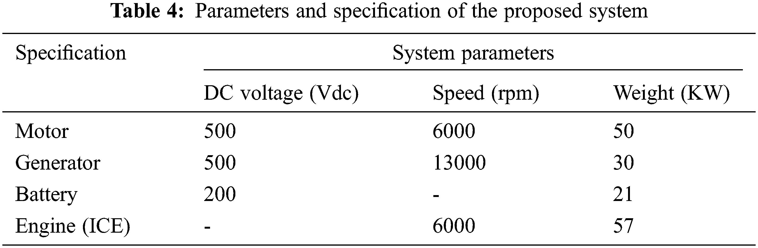
The three-phase machine may be an EMF waveform on the sinusoidal or trapezoidal back. For the sinusoidal machine the rotor may be round or salient-pole, it is round when the machine is trapezoidal. Present models are available for the sinusoidal back EMF machine as shown in Figs. 5a and 5b, and the parameter values of Tab. 4. The Electrical Subsystem named Permanent Magnet Synchronous Machine (PMSM) generator drive shows the results for the motor drive.

Figure 5: PMSM motor and generator drive efficiency (current, speed and torque). (a) Motor (b) Generator
The Planetary Gear Subsystem is a set of carrier, ring, and sun gears which restrict the connected driveline axes. The gear ratio is gear teeth ratio (gear radii ratio). The ring and the sun have a constant gear ratio relative to the carrier, and in opposite directions. As shown in Fig. 6a, the ring-sun gear power ratio has to be strictly greater than one. Torque sensor measures the torque being transferred along an axis of the driveline. If the follower accelerates in the positive direction a positive torque is transferred from the base (B) axis to the follower (F) axis. A torque sensor is a device for measuring and recording the torque on a rotating system, such as an engine, crankshaft, gearbox, transmission, rotor, bicycle crank, or Cap Torque Tester. Static torque is relatively easy to measure. The torque is being output in N*m as a Simulink signal. To model the planet's rotational depression, a recession module is connected to a custom planetary connection port, as shown in Fig. 6b. The motion sensor measures the movement of an axis driveline. The combination of angle, angular velocity, and angular acceleration at rad, rad/s, and rad/s # 2 was measured by selecting the appropriate velocity output ports, respectively, as shown in Fig. 6c. The measured angle is the initial angle plus the angular velocity integral time, from the start. Allow zero detection for real inputs, output 1 for positive input, −1 for negative input and 0 for input 0. The outputs for complex inputs of floating points follow sign (u) = u. /Abs(u) of planetary gears in relation to Willis and the power law as shown in Fig. 6d.

Figure 6: Power planetary gear efficiency (carrier, sun and ring). (a) Power (b) Torque (c) Speed (d) Gear
The simple petrol fuel engine model of the speed governor is a wet winding spring with a recess. The relative motion is the followers (F) axis minimizes the base (B) axis. Only the angular penetration beyond the backlash is used to compute the restoring spring torque. Power generator and power battery as shown in Fig. 7a. The battery power provides a sub-system or model with the output port. Generator power controls the second input range by first (upper limit) and third (lower limit) input. The hybrid relay releases a specific ‘on’ or ‘off’ value by comparing the input to specific thresholds. The on/off position of the relay is not affected by the input between the upper and lower limits as shown in Fig. 7b. The main system named as the vehicle shows the acceleration level, car speed, drive torque and power flow as shown in Fig. 7c.

Figure 7: Efficiency (throttle and engine speed, torque, power). (a) Engine (b) EMS (c) Vehicle
Relationship between drive power and the required torque as shown in Fig. 8. Provide an input port for a subsystem or model. For triggered subsystems, the ‘latch input by delaying the external signal’ generates the value of the subsystem input at the previous time point. For functional-call subsystems, turning on the Latch input to the feedback signals of functional-call subsystem outputs prevents the input value of this subsystem from changing during its operation.

Figure 8: Relation between the require torque and drive power efficiency
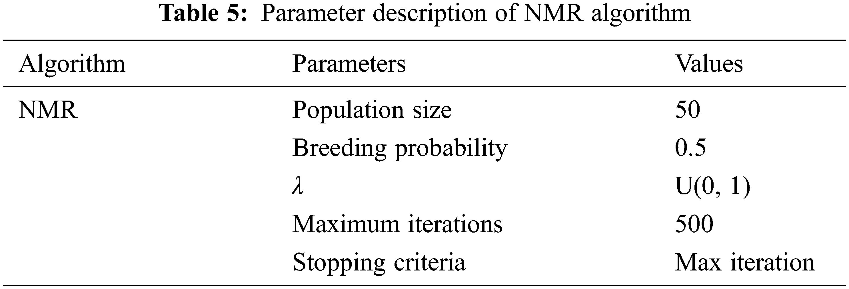
In addition, the integrated optimization algorithm upgrades the original optimization model, and the approximate model respectively shows the performance of the NMR as shown in Tab. 5.
Open the car in the main setting. The following explains what happens when a hybrid electric vehicle (HEV) moves.
At T = 0 s, the hybrid electric vehicle (HEV) is stopped and the driver accelerates and pushes the pedal to 72%. The generator and ICE (internal combustion engine) provide no power. At T = 1.4 s, the required power exceeds 14 kW inducing the hybrid model. In this case, the hybrid electric vehicle (HEV) power comes from the internal combustion engine (ICE) and the battery (via motor). This operating system corresponds to the acceleration as shown in Fig. 9a. At T = 2 s, the hybrid electric vehicle is stopped and the driver accelerates and pushes the pedal to 86%. Until the required power is less than 14 kW, the hybrid electric vehicle (HIV) moves using only the electric motor power supplied by the battery. The generator and ICE did not provide any of the power shown in Fig. 9b. At T = 4 s, the accelerator pedal is released for 10% (travel mode). The internal combustion engine (ICE) cannot immediately reduce its power; so the battery generator absorbs power to reduce the required torque as shown in Fig. 9c. At T = 4.4 s, the generator shuts off completely. The required power is supplied only by the battery as shown in Fig. 9d.


Figure 9: Vehicle efficiency. (a) (At t = 1.4 s) (b) (At t = 2 s) (c) (At t = 4 s) (d) (At t = 4.4 s) (e) (At t = 8 s) (f) (At t = 8.4 s) (g) (At t = 14 s)T = 0
At T = 8 s, the accelerator pedal is pushed to 87%. The internal combustion engine (ICE) is restarted to provide the additional required power as shown in Fig. 9e. At T = 8.4 s the torque measured reaches the reference point as shown in Fig. 9f. The generator delivers maximum output. At T = 10 s, the battery state-of-charge (SOC) drops to less than 40% (which started at 41.53% at the beginning of the simulation) so the battery needs to be recharged. The accelerator pedal at T = 14 s is set at −70 percent (regenerative braking is simulated). This is done by turning off the generator (it takes 0.5 s to reduce the power of the generator to zero), the required torque of −250 Nm cannot be achieved for this pedal level, since the battery can absorb only 21 kW of power as shown in Fig. 9g. The generator power is completely discontinued at T = 14.4 s.
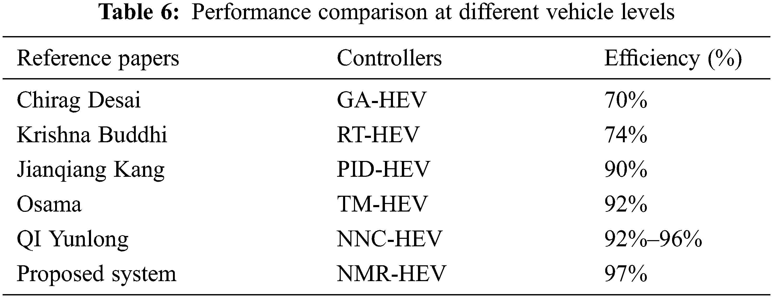
Tab. 6 provides performance comparisons with respect to vehicle performance for different control systems by specifying different manuscripts. The proposed method showing the highest performance than the other methods can be seen from the table.
This study presents use of effective energy management system for hybrid electric vehicle with CAN bus communication. This simulation tool is seen as an aid in the design and evaluation of an electric hybrid vehicle. The driveline components can vary and explore the impact a hybrid electric vehicle will have on fuel efficiency. Both simulation devices have a model for a simulated vehicle in which the driveline components are referred to as interconnected modules that communicate seconds-level body signals with each other. Simulation input is a direction with a reference speed for the vehicle as time function. Any simulated signal may be desired at the output. During the full simulation, you can observe the DC bus voltage of a well-regulated electrical system at 500 V, the initial parameter design of the motor is calculated to optimal design under actual dimensions with the advantage of the optimization effect. The CAN-bus automatically decrease the number of line on system that connecting between sensor and its can applied for research artificial applications purpose of HEV. This technology, respects standard CAN-bus and realizes security mechanisms implemented in software or hardware, while adding less than 1 ms latency on the communication. The naked mole-rating (NMR) optimization algorithm mainly improves motor design parameters, which increases the efficiency of the equivalent operating point by 86 percent. By using the dynamic hybrid electric vehicle (HEV) model to verify, the power losses of the motor are reduced by 18.35%. Higher motor performance thus results in a better fuel economy, but the level of emissions is slightly worse. We have stated in it that the naked mole rat optimization technique increases the efficiency by improving the Kp, Ki value. It is no longer said that future paper will increase efficiency even more when compared to a lot of algorithms.
Acknowledgement: The author with a deep sense of gratitude would thank the supervisor for his guidance and constant support rendered during this research.
Funding Statement: The authors received no specific funding for this study.
Conflicts of Interest: The authors declare that they have no conflicts of interest to report regarding the present study.
1. H. Jeongheon and R. Skelton, “An LMI optimization approach for structured linear controllers,” in Proc. IEEE Int. Conf. on Decision and Control, Maui, HI, USA, pp. 5143–5148, 2003. [Google Scholar]
2. C. Desai and S. W. Sheldon, “Comparative study of hybrid electric vehicle control strategies for improved drivetrain efficiency analysis,” in Proc. IEEE Electrical Power & Energy Conf., Montreal, QC, Canada, pp. 1–6, 2009. [Google Scholar]
3. K. Buddhi and U. Hebbar, “An alternative method to improve efficiency of plug-in hybrid electric vehicles,” in Proc. IEEE Symp. on Industrial Electronics and Applications, IEEE, Bandung, Indonesia, pp. 210–213, 2012. [Google Scholar]
4. P. Zhang, C. Du, F. Yan and J. Kang, “Energy efficiency of a Ni-MH battery used in hybrid electric vehicles,” in Proc. Int. Conf. on Electric Information and Control Engineering, Wuhan, China, pp. 4996–4999, 2011. [Google Scholar]
5. S. A. Zulkifli, S. Mohd, N. Saad and A. R. A. Aziz, “Influence of motor size and efficiency on acceleration, fuel economy and emissions of split-parallel hybrid electric vehicle,” in Proc. IEEE Symp. on Industrial Electronics & Applications, Kuching, Malaysia, pp. 126–131, 2013. [Google Scholar]
6. X. Ye, Z. Jin, X. Hu, Y. Li and Q. Lu, “Modeling and control strategy development of a parallel hybrid electric bus,” International Journal of Automotive Technology, vol. 14, no. 6, pp. 971–985, 2013. [Google Scholar]
7. H. Zhang, C. L. Wang, Y. Zhang, J. Y. Liang and C. L. Yin, “Drivability improvements for a single-motor parallel hybrid electric vehicle using robust controls,” Journal of Zhejiang University Science A, vol. 15, no. 4, pp. 291–301, 2014. [Google Scholar]
8. F. Payri, C. Guardiola, B. Pla and D. B. Rodriguez, “A stochastic method for the energy management in hybrid electric vehicle,” Control Engineering Practice, vol. 29, pp. 257–265, 2014. [Google Scholar]
9. S. Kitayama, M. Saikyo, Y. Nishio and K. Tsutsumi, “Torque control strategy and optimization for fuel consumption and emission reduction in parallel hybrid electric vehicles,” Structural and Multidisciplinary Optimization, vol. 52, no. 3, pp. 595–611, 2015. [Google Scholar]
10. Q. I. Yunlong, W. Weida and X. Changle, “Neural network and efficiency-based control for dual-mode hybrid electric vehicles,” in Proc. Chinese Control Conf., Hangzhou, China, pp. 8103–8108, 2015. [Google Scholar]
11. A. D. O. D. S. Dantas, A. F. O. D. A. Dantas, J. T. L. Campos, D. L. D. A. Neto and C. E. T. Dorea, “PID control for electric vehicles subject to control and speed signal constraints,” Journal of Control Science and Engineering, vol. 2, pp. 4052–4059, 2018. [Google Scholar]
12. M. Montazeri and M. Mahmoodi, “Development a new power management strategy for power split hybrid electric vehicles,” Transportation Research Part D: Transport and Environment, vol. 37, pp. 79–96, 2015. [Google Scholar]
13. S. Y. Chen, Y. H. Hung, C. H. Wu and S. T. Huang, “Optimal energy management of a hybrid electric powertrain system using improved particle swarm optimization,” Applied Energy, vol. 160, pp. 132–145, 2015. [Google Scholar]
14. S. Yun, K. Lee and K. Yi, “Development of a power management strategy to minimize the fuel consumption of a heavy-duty series hybrid electric vehicle,” Journal of Mechanical Science and Technology, vol. 29, no. 10, pp. 4399–4406, 2015. [Google Scholar]
15. V. Kumar, K. P. S. Rana and P. Mishra, “Robust speed control of hybrid electric vehicle using fractional order fuzzy PD and PI controllers in cascade control loop,” Journal of the Franklin Institute, vol. 353, no. 8, pp. 1713–1741, 2016. [Google Scholar]
16. A. Appathurai and P. Deepa, “Design for reliablity: A novel counter matrix code for FPGA based quality applications,” in Proc. Asia Symposium on Quality Electronic Design, Kula Lumpur, Malaysia, pp. 56–61, 2015. [Google Scholar]
17. M. F. M. Sabri, K. A. Danapalasingam and M. F. Rahmat, “A review on hybrid electric vehicles architecture and energy management strategies,” Renewable and Sustainable Energy Reviews, vol. 53, pp. 1433–1442, 2016. [Google Scholar]
18. S. Padhy and S. Panda, “A hybrid stochastic fractal search and pattern search technique-based cascade PI-PD controller for automatic generation control of multi-source power systems in presence of plug-in electric vehicles,” CAAI Transactions on Intelligence Technology, vol. 2, no. 1, pp. 12–25, 2017. [Google Scholar]
19. G. Pancholi, D. K. Yadav and L. Chaturvedi, “Comparative analysis of hybrid electric vehicle FED through DC-DC converter and operated with battery and ultracapacitor,” in Proc. Int. Conf. on Information, Communication, Instrumentation and Control, IEEE, Indore, India, pp. 1–6, 2017. [Google Scholar]
20. M. J. Li, Y. L. He and W. Q. Tao, “Modeling a hybrid methodology for evaluating and forecasting regional energy efficiency in China,” Applied Energy, vol. 185, pp. 1769–1777, 2017. [Google Scholar]
21. H. Cui and G. Xiao, “Fuel-efficiency technology trend assessment for LDVs in China: Hybrids and electrification,” The International Council on Clean Transportation, vol. 1, no. 2, pp. 18–19, 2018. [Google Scholar]
22. Y. Zhang, X. Dai, X. Han and X. Jin, “Analysis of impact of electric vehicle charging load on city grid,” IOP, Materials Science and Engineering, vol. 486, no. 1, pp. 012139, 2019. [Google Scholar]
23. W. Dong, H. He and J. Cao, “Hybrid electric vehicle electric motors for optimum energy efficiency: A computationally efficient design,” Energy, vol. 203, pp. 117779, 2020. [Google Scholar]
24. W. B. Nader, “Thermoelectric generator optimization for hybrid electric vehicles,” Applied Thermal Engineering, vol. 167, pp. 114761, 2020. [Google Scholar]
25. G. Prathiba, M. Santhi and A. Ahilan, “Design and implementation of reliable flash ADC for microwave applications,” Microelectronics Reliability, vol. 88, pp. 91–97, 2018. [Google Scholar]
26. G. Kornaros, O. Tomoutzoglou, D. Mbakoyiannis, N. Karadimitriou, M. Coppola et al., “Towards holistic secure networking in connected vehicles through securing CAN-bus communication and firmware-over-the-air updating,” Journal of Systems Architecture, vol. 109, pp. 101761, 2020. [Google Scholar]
27. K. Ismail, M. Muharam and P. Mulia, “Design of CAN bus for research applications purpose hybrid electric vehicle using ARM microcontroller,” Energy Procedia, vol. 68, pp. 288–296, 2015. [Google Scholar]
 | This work is licensed under a Creative Commons Attribution 4.0 International License, which permits unrestricted use, distribution, and reproduction in any medium, provided the original work is properly cited. |