DOI:10.32604/iasc.2022.023470
| Intelligent Automation & Soft Computing DOI:10.32604/iasc.2022.023470 | |
| Article |
Hybrid Sensorless Speed Control Technique for BLDC Motor Using ANFIS Automation
Department of EEE, St. Xavier’s Catholic College of Engineering, Kanyakumari, 629003, India
*Corresponding Author: S. S. Selva Pradeep. Email: selvapradeep20201@gmail.com
Received: 09 September 2021; Accepted: 09 November 2021
Abstract: The Brushless Direct Current (BLDC) motors have shown to be a cost-effective alternative to traditional motors. The smooth and efficient operation of the BLDC motor is dependent on speed regulation. This research proposes a sensorless intelligent speed control technique for BLDC using an Adaptive Network-based Fuzzy Inference Systems (ANFIS) based Artificial Bee Colony (ABC) algorithm. The motor’s back EMF is measured, and ANFIS is used to generate Hall signals. The ABC is then utilized to provide the pulses needed for the three-phase inverter, avoiding the requirement of logic gate circuits. The input DC voltage to the inverter is controlled by a PI controller. The Optimized Field Oriented Control (OFOC) is implemented to control the sensorless BLDC motor. The proposed method is implemented and the outcomes are analyzed by MATLAB/SIMULINK and there is no overshoot and have low settling time and also the steady state error is very low than the existing methods. This proposed method can be improved by reducing the number of ANFIS controllers by incorporating a single controller whose main parameters shall be optimized by latest optimization techniques, and the results reveal that the proposed strategy is effective in managing the motor’s speed.
Keywords: Artificial bee colony algorithm; ANFIS; BLDC motor; PI controller; sensorless control
In recent years, BLDC motor is broadly used in industries and home due to its better performance, higher power density and lesser noise compared to other motors. In many industries and organizations, conventional fans are being replaced by energy efficient BLDC fans for saving energy consumptions. Based on the magnetic field energizing and motor winding current the speed of BLDC motor is controlled. As a result, the rotor current and voltage can be adjusted to control the motor speed [1]. Several studies have presented several speed control approaches for BLDC motors with Hall sensors [2]. ANFIS was created to operate a matrix converter supplied BLDC motor and was optimized using the Bacterial Foraging algorithm [3,4]. Few approaches [5–7] use intelligent algorithms to control the input DC voltage to the inverter, while the pulses are generated using signals from Hall sensor of the BLDC motor. Few other approaches [8] use intelligent algorithms to control the modulating signal and to generate pulses to the Inverted fed BLDC motor. However, the above said techniques uses hall sensors to detect the relative position of the rotor with respect to three phase stator windings. These hall sensors have limitation of poor performance during high temperatures which make the system to be unstable [9].
Sensorless control has emerged as an alternative to overcome the limitations of using sensors. Researchers have proposed several sensorless control techniques for BLDC motor [10–13]. Some of these techniques [14] use conventional methods and some other [15] uses intelligent techniques. However these methods use complex mathematical models and logical blocks in implementation.
Recently, the sensorless control of PMBLDC motor drive via hybrid control of Z source inverter adopts fuzzy logic control approach is presented. ZSI are used for changeable input voltage and are regulated with all typical PWM systems [16]. Sensorless BLDC drive speed control using the zero-crossing detection of indirect back EMF approach is presented recently. Thus, the result shows, hybrid of fuzzy-PI controller shows the better performance than the fuzzy logic, anti-windup-PI and conventional PI [17]. The Control strategy of PWM is applied using an Arduino uno hardware prototype that was created and built, and the effectiveness of the approaches is demonstrated are evaluated, the current cutting methods can reduce torque peaks during startup.
Recently fuzzy logic based switching technique has been implemented which simplified the logic gates design [18,19]. Artificial Bee Colony (ABC) is one of the strategies used to identify the best solution to complicated issues. The ABC algorithm is recreated by mimicking the activity of honey bees while looking for a good food source. This approach is a fast, simple & population-based stochastic search algorithm influenced by honey bee seeking behaviour. This introductory section of the paper is followed by proposed methodology, simulation results and analysis.
This section describes the ABC optimised ANFIS controller’s systematic design approach for sensorless speed regulation of a BLDC motor. During the first phase, the BLDC motor model parameters are determined based on the motor specifications, as well as an initial range of ANFIS controller settings. In the proposed work, the developed back EMF in the stator of the BLDC motor is converted to hall signals using an ANFIS controller. The ABC controller is then used to convert the hall signals to pulses required for the three phase inverter, meanwhile PI controller controls the DC input to the inverter. A simplified block diagram of the suggested system is specified in Fig. 1. The proposed work’s design constraints are following: Settling time (
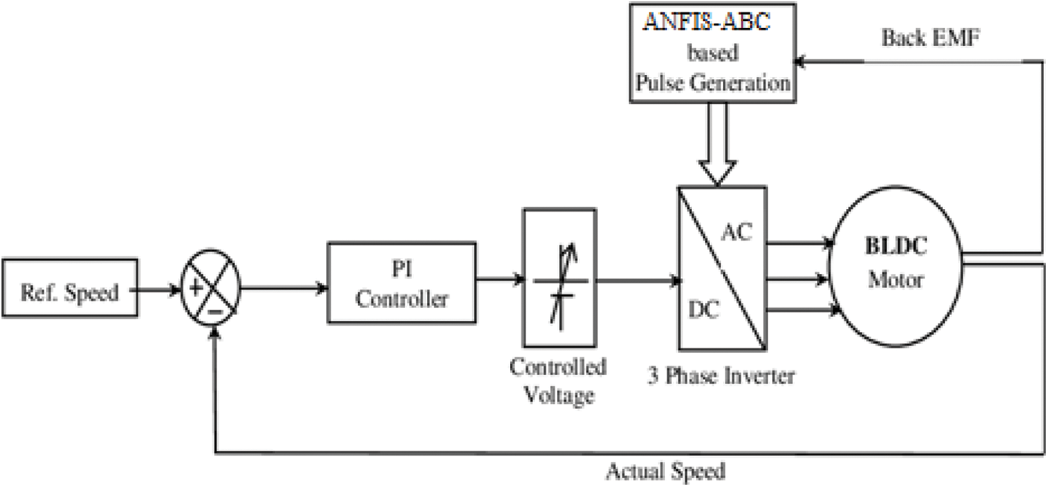
Figure 1: Block diagram of the proposed methodology
The ANFIS is an intelligent tool [20] used for prediction and control [21,22]. The ANFIS controller’s job in this project is to produce hall signals from the BLDC motor’s stator back EMF. Three distinct ANFIS controllers, one for each hall signal, have been designed. Each ANFIS block is built with 3 inputs (Back EMF at 3 phases) and one output (Hall Signal for one phase). The ANFIS controllers are trained with 10000 training samples having 5 membership functions for each input and grid partition techniques is used to generate the fuzzy inference system. Triangular membership function [23] is used for the inputs and constant membership function is used for output.
Fig. 2 shows the proposed ANFIS controller for generating Hall signals. For this work the triangle membership function (Trimf) is applied, because compared with others, the triangle membership function is the simplest form with a triangular curve. It is specified by three factors that define three points: b for the curve’s tip, c and a for the feet. The following Eq. (1) expresses the mathematical formula of triangle membership function.

Figure 2: ANFIS controller for generating hall signals
The ANFIS is trained using hybrid learning rule with 125 rules for generating the output. The obtained training error is 0.0812. Since the value of Hall signal should be either 1 or 0, a rounding function is used at the output side of each ANFIS to generate the required Hall signals [24].
2.2 Artificial Bee Colony (ABC)
The Artificial Bee Colony algorithm is based on the behavior of wild bees to find the best solution to limited situations. The ABC algorithm has the following characteristics: (i) minimal control parameters, (ii) quick convergence ratio and computing time, (iii) exploration and exploitation, and (iv) adaptability is good. There are three types of bees in the ABC algorithm: employed bees, observer bees, and scout bees. The first part of this algorithm consists of employed bees, whereas the remaining part of the algorithm consists of observer bees. The quantity of bees utilised is proportional to the amount of food available in the natural environment. One hired bee, in particular, exploits every food source accessible in the natural environment. When the hired bee’s food supply is depleted, it becomes a scout bee. The position of a food source provides a possible solution to be optimised in the ABC algorithm. The fitness of the optimum solution corresponds to the profitability of the food supply. The ABC algorithm involves the following steps:
where, D—vector dimensional,
The algorithm’s essential phases are outlined below.
Step 1: Initialize bee’s food location
Step 2: With the success of the improved food source, all employed bees discovered another food source at her nutrition supply site—fitness call function—current and voltage measurements for BLDC motors [
Step 3: Depending on the value of the bee’s solution, each onlooker bee creates a new food source and takes advantage of the superior food supply:
Step 4: Identify the deserted source and send its employed bee as a scout to look for other food sources:
Step 5: Remember the finest food source you’ve discovered so far (
Step 6: Repeat steps 2–5 of the ABC method until the stopping ideal parameter values are achieved.
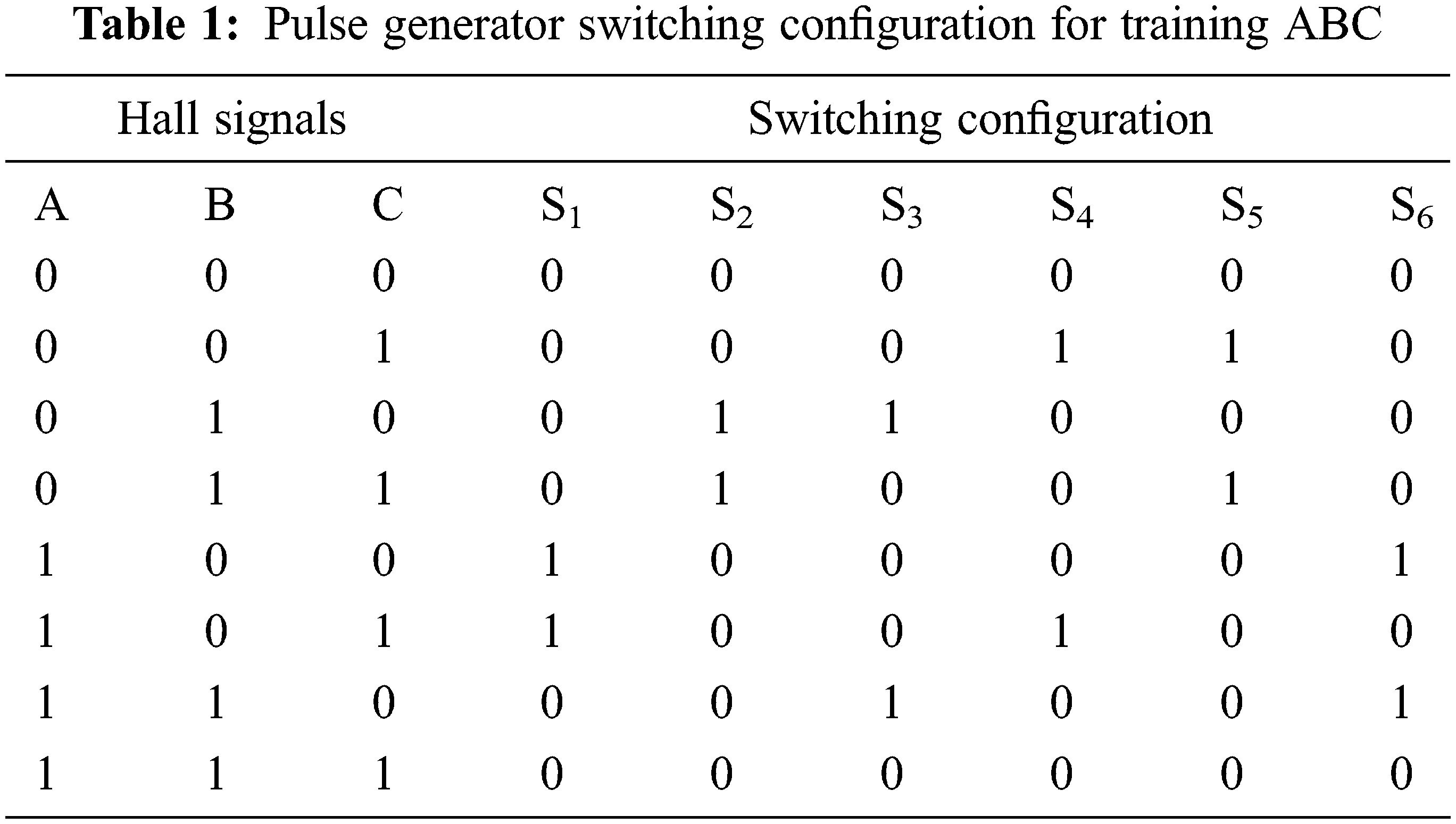
Fig. 3 shows the flowchart for ABC algorithm. The ABC’s flowchart depicts the fundamental execution phases for determining the best controller settings with ABC. It begins by initializing the controller parameter boundary values, design requirements, and updated time domain specifications. The ABC algorithm is used to extract the optimal parameters from the design requirements, updated time domain, and controller parameters. Finally, the condition is satisfied when the steady state error and settling time are within the limit. ABC finds many applications in electrical engineering in the areas of prediction and control. In this work, a new approach to generate switching pulses directly from ABC is proposed and implemented. A back propagation neural network is created and trained based on the switching configuration presented in Tab. 1.

Figure 3: ABC algorithm’s flowchart
3 Optimized Field Oriented Control
A brushless motor Optimized Field Oriented Control (OFOC) is currently being developed; it might also be used to successfully develop motor pump units for automotive applications. FOC is reported to be more efficient than back-EMF zero crossing detection methods in terms of torque generation. The BLDC motor’s speed control has three inputs and six switching functions. The sensorless controlling algorithm is implemented in this work and it control the first position of the rotor with respective with the switching configuration of the neural network. Most sensorless control systems based on back-EMF detection can perform satisfactorily in steady-state circumstances when running at medium to high speed control ranges. The motor, on the other hand, fails when it comes to a halt or is running at a slow speed. Therefore, to speed up the process, a certain starting procedure should be applied. Sensorless algorithms can speed up a motor to a particular speed work in a reasonable manner. Fig. 4 illustrates the sensorless FOC algorithm’s block diagram.
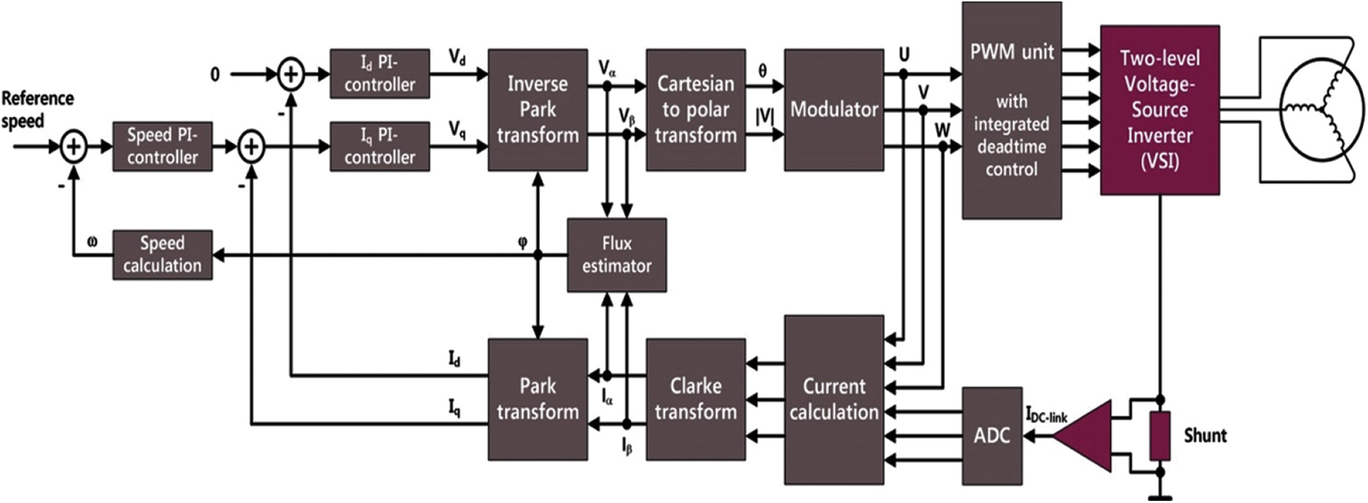
Figure 4: Sensorless FOC algorithm’s block diagram
where,
Fig. 5 depicts the flow chart of the sensorless algorithm. The back-EMF detection method cannot be employed at low speeds or when the motor is stopped since the back-EMF is proportional to the motor speed. Despite this limitation, the motor can be started from a standstill using a starting process. In essential applications such as intelligent electro-mechanical (EMA) and electro-hydraulic (EHA) actuators in aviation systems, precision start-up of a DC motor is required. Electrical commutation is typically accomplished in the initial running stage by using a traditional PWM signal that energies a transistor power stage. The pulses produced by ANFIS are presented in Fig. 5.
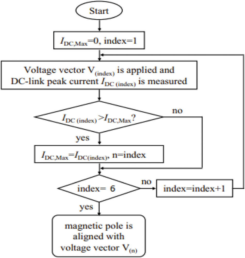
Figure 5: Flow chart of sensorless algorithm
The flux estimator calculates the rotor flux by subtracting all voltage drops not related to the back EMF from the applied phase voltage. After that, the estimated back-EMF is used to find the rotor flux. When the applied phase voltage or measured current is not perfect, as in low-speed operation, sensorless algorithms are less reliable. The flux estimator’s input signals in this example come from an orthogonal two-phase stator system with the index and. The rotor angle is represented by the output signal.
The initial rotor position computation is dependent on the DC-link current response when voltage vectors are used, therefore the voltage vectors’ amplitude and output time are critical. Because the amplitude is determined by the DC-link voltage, we can only measure their output time.
Once the rotor’s initial location has been known, the starting voltage vector may be calculated. However, in the n accelerating phase, we must update the rotor position. However, when the motor is rotating, the previously indicated detecting mechanism may produce a reverse torque. As a result, a certain starting procedure must be followed.
4 Simulation Output and Analysis
In this section, system modeled and simulated by MATLAB/SIMULINK to validate the effectiveness of the suggested methodology. Under constant load, no load, and fluctuating load situations, speed response features of two different set speeds are investigated. The results are compared to methods that have already been published in the literature. The simulation plan for the proposed system is exposed in Fig. 6.
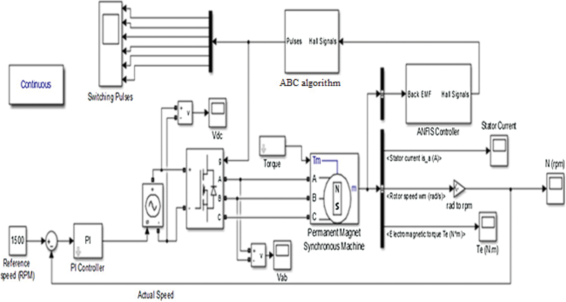
Figure 6: Simulation plan of the suggested speed controller of the BLDC motor
The main conditions of selecting BLDC motor are; voltage constant—86.96, torque constant—0.84, flux linkage—0.105, stator phase resistance—0.7 Ω, stator phase inductance—2.72 mH. Two reference speeds, 1500 rpm and 1200 rpm are considered for 3 different operating conditions (no load, constant load and varying load) are considered for the analysis. For all working situations, the controller gain parameters of the PI controller are set to KP = 0.002 and KI = 10. The proposed ANFIS-ABC controller of stator back EMF of sensorless BLDC motor on reference speed 1500 rpm with no load condition of speed and torque.
Initially, the simulation is run for a set/reference speed of 1500 rpm. The stator EMF and the hall signals generated by ANFIS under no load condition are presented in Figs. 7a–7c. The switching pulses required for the three-phase inverter depicted in Fig. 8 are generated by an ABC-based pulse generator. The Fig. 9 represents the drive’s Torque response with ANFIS controller.
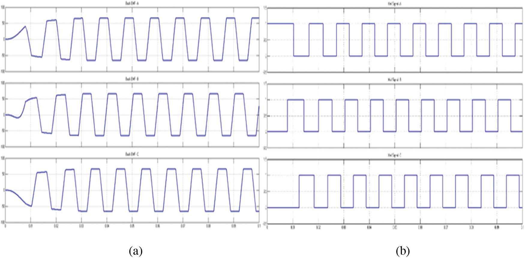
Figure 7: (a) Stator back EMF of 3 phases of BLDC motor. (b) Hall signals generated by ANFIS
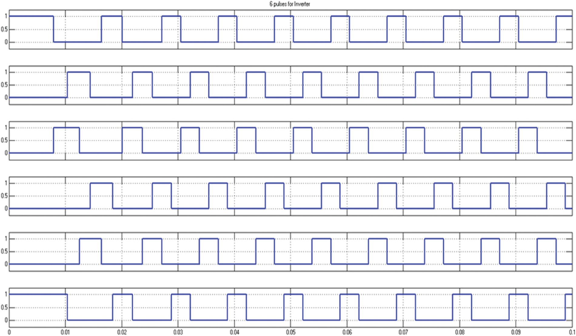
Figure 8: Switching pulses for inverter generated by back propagation ABC
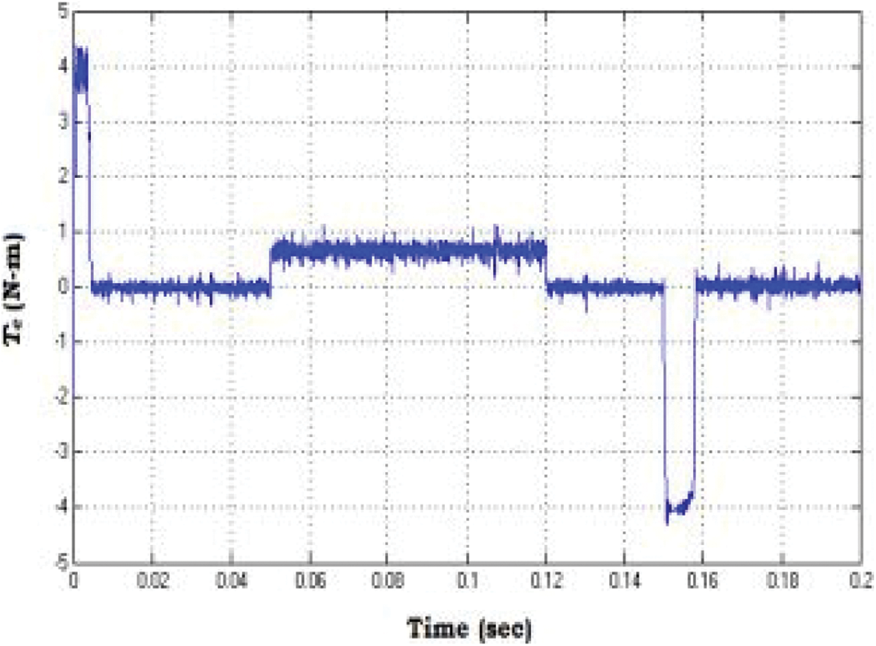
Figure 9: Drive’s torque response with ANFIS controller
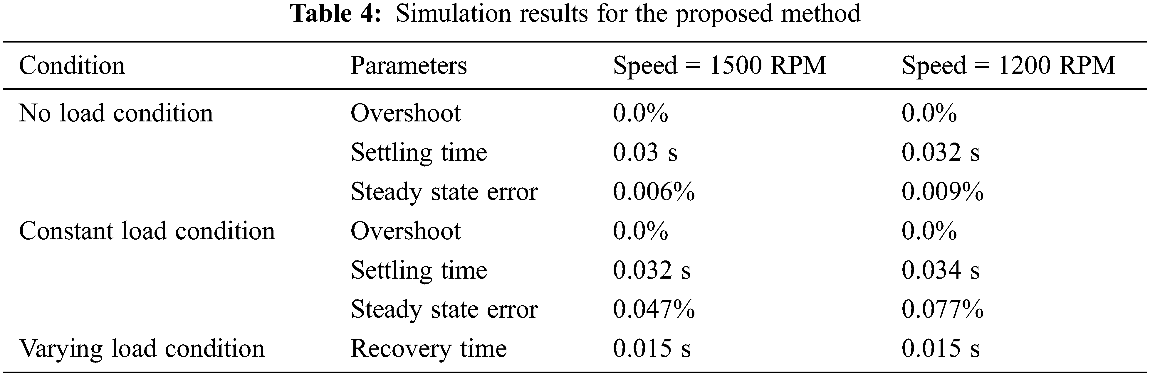
During no load condition, BLDC motor reaches the steady state speed of 1500 rpm in 0.03 s. The steady state error is equivalent to 0.09 rpm (0.006%). With a constant load of 1.5 Nm applied to the motor, the steady state speed error equals to 0.7 rpm (0.047%). The system is then simulated under varying load condition (i.e., Torque of 0.75 Nm from 0 to 0.25 s and 1.5 Nm from 0.25 to 0.5 s). The motor experiences a dip of 28 rpm from its normal speed and takes 0.02 s before it recovers to the normal operating speed. The DC input voltage to the inverter is controlled by the PI controller. The speed increases practically linearly with time and gently approaches the required value. The time response values speed of 1500 RPM are expressed as follows: settling time
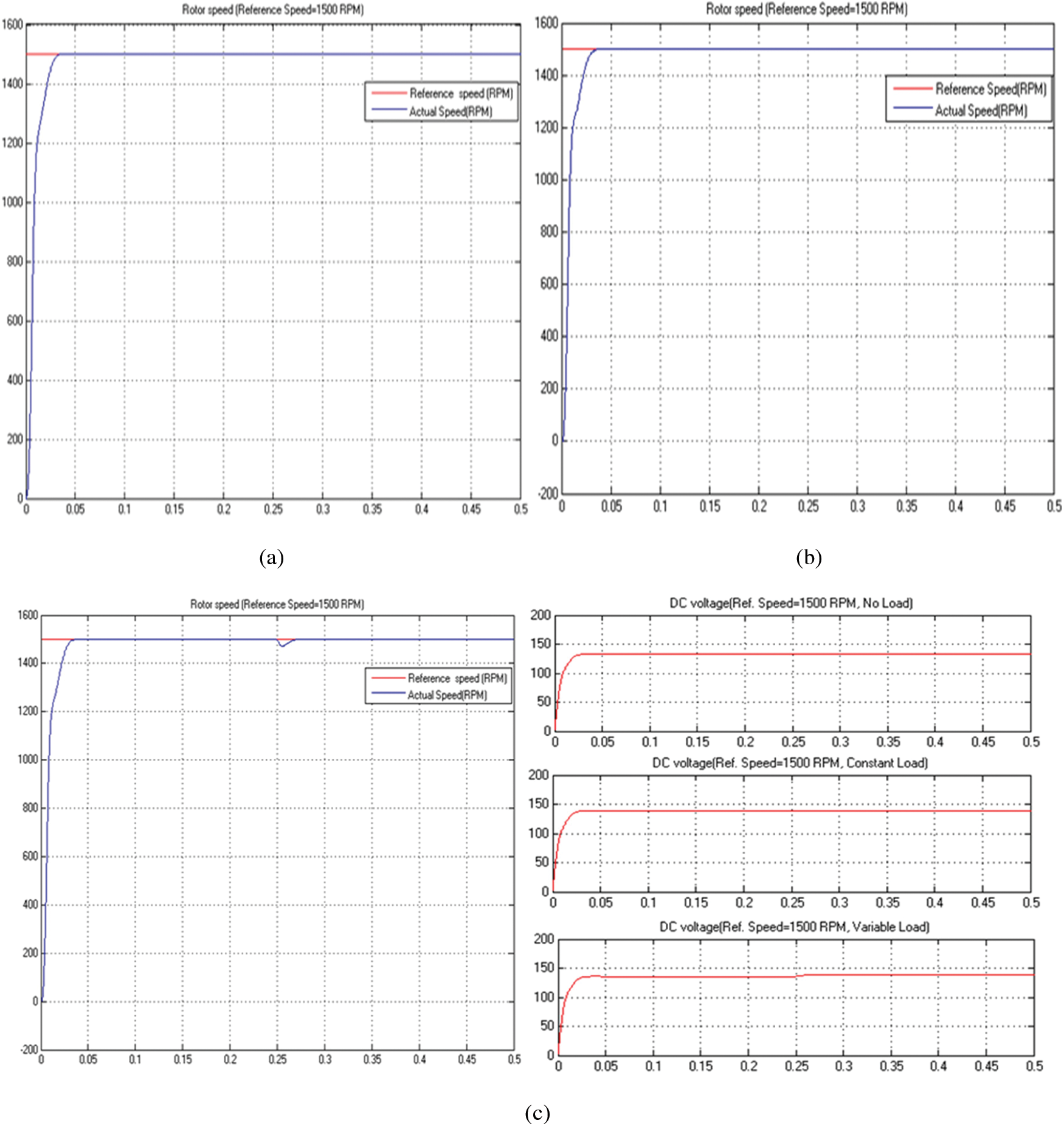
Figure 10: Speed characteristics of BLDC motor for no load, (a) Constant load, (b) Variable load, (c) DC voltage to the inverter for 3 loading conditions for set speed of 1500 RPM
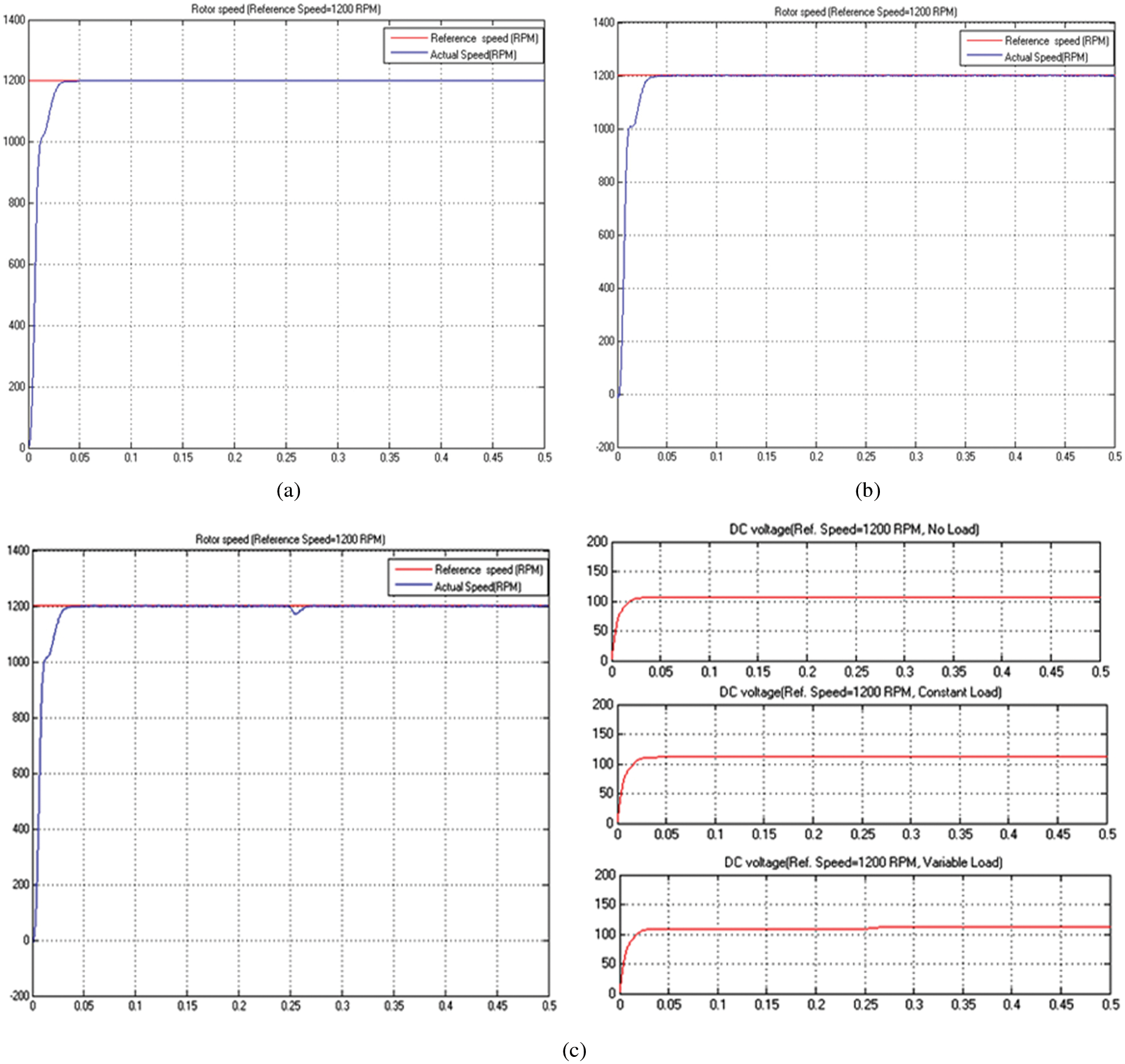
Figure 11: Characteristics of BLDC motor for no load, (a) Constant load, (b) Variable load, (c) DC voltage to the inverter for 3 loading, Conditions for set speed of 1200 RPM
The Tab. 2 shows the enactment analysis of the proposed Hybrid technique of ANFIS & ABC with OFOC to the existing methods. The following Fig. 12 shows the comparison of overshoot, settling time (s) and steady state error (%) for various existing method and proposed method. By this compression the research found out the proposed method have no overshoot, low settling time and also the steady state error is very low than the existing methods. The results depict the effectiveness of the suggested system under different reference speed conditions. Tab. 3 shows the comparison of different controllers with proposed method under no load and load condition.
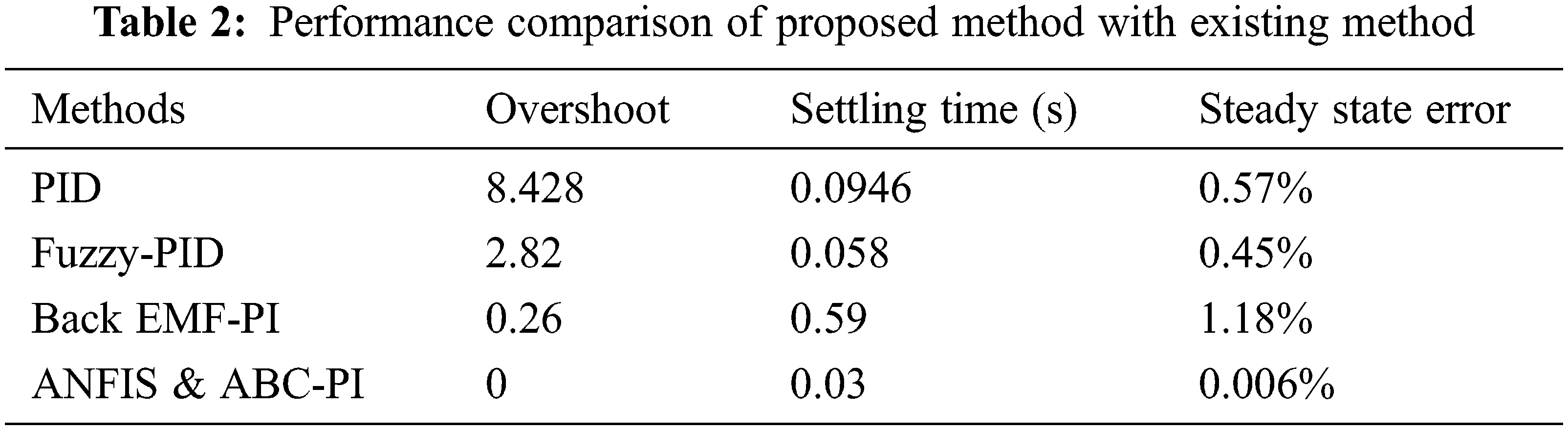

Figure 12: Comparison of (a) overshoot (b) settling time (c) steady state error for existing method with proposed method
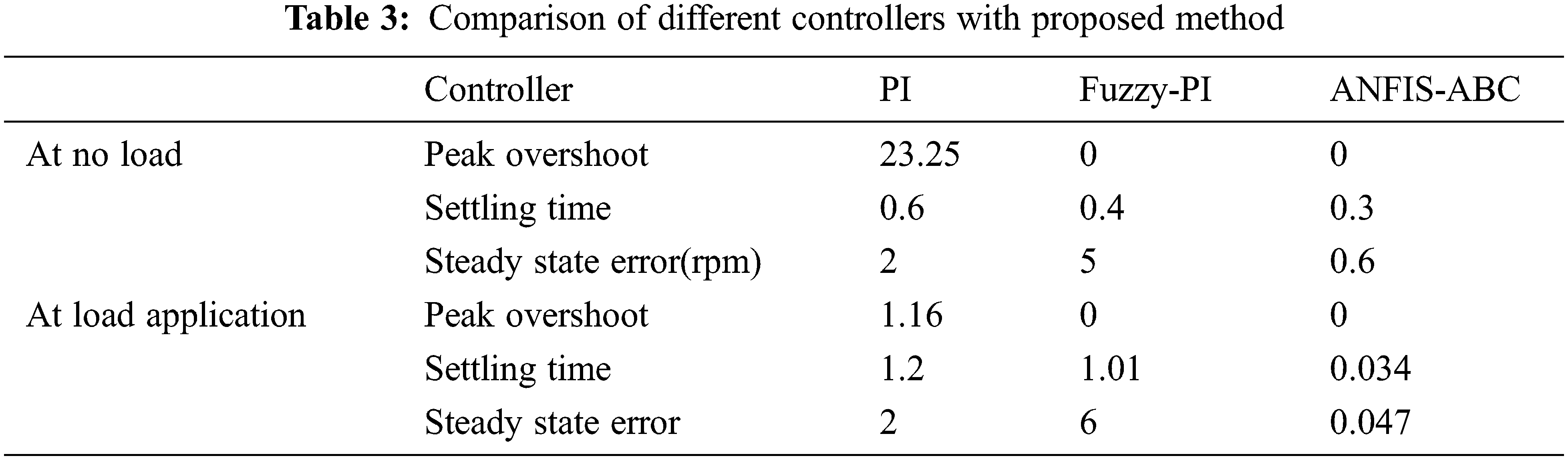
It demonstrates that the PI controller has a high Peak Overshoot under no load and load torque scenarios. In addition, the PI controller has a longer settling time. Though the fuzzy-PI controller provides a smooth response with no peak overshoots and is faster than the PI controller, the proposed ANFIS-ABC provide no overshoot, low settling time and also the steady state error is very low than the existing methods. The consolidated results are presented in Tab. 4.
The proposed method simplifies the mathematical and logical modelling of inverter switching circuits for BLDC motor position sensorless control. The results reveal that the proposed strategy is effective in managing the motor’s speed. This research work mainly considered only the switching portion, compared to less concentration on the input side. In future work, intelligent control schemes to control the gain parameters of PI controller will be considered.
A new methodology for speed regulator for sensorless BLDC motor is proposed and tested in this paper. The ANFIS controller to generate Hall signals eliminates the use of Hall sensors and the ABC based pulse generation eliminates the logic gate circuits generally used for generating switching pulses. A PI controller controls the input DC voltage to the three phase inverter. The proposed methodology’s simulation results have shown that it is effective for controlling the speed of a BLDC motor under various operating situations. Besides, the method can be improved by reducing the number of ANFIS controllers by incorporating a single controller whose main parameters shall be optimized by latest optimization techniques.
Acknowledgement: The author with a deep sense of gratitude would thank the supervisor for his guidance and constant support rendered during this research.
Funding Statement: The authors received no specific funding for this study.
Conflicts of Interest: The authors declare that they have no conflicts of interest to report regarding the present study.
1. S. Gopinath and M. Madeswaran, “Deep perceptron neural network with fuzzy PID controller for speed control and stability analysis of BLDC motor,” Soft Computing, vol. 24, no. 13, pp. 10161–10180, 2020. [Google Scholar]
2. T. S. Sivarani, J. S. Joseph and C. A. Kumar, “Novel bacterial foraging-based ANFIS for speed control of matrix converter-fed industrial BLDC motors operated under low speed and high torque,” Neural Computing and Applications, vol. 29, no. 12, pp. 1411–1434, 2018. [Google Scholar]
3. K. Premkumar and B. V. Manikandan, “Stability and performance analysis of ANFIS tuned PID based speed controller for brushless DC motor,” Current Signal Transduction Therapy, vol. 13, no. 1, pp. 19–30, 2018. [Google Scholar]
4. A. Varshney, D. Gupta and B. Dwivedi, “Speed response of brushless DC motor using fuzzy PID controller under varying load condition,” Journal of Electrical Systems and Information Technology, vol. 4, no. 2, pp. 310–321, 2017. [Google Scholar]
5. K. Premkumar and B. V. Manikandan, “Fuzzy PID supervised online ANFIS based speed controller for brushless DC motor,” Neuro Computing, vol. 157, no. 4, pp. 76–90, 2015. [Google Scholar]
6. A. Kiruthika, A. A. Rajan and P. Rajalakshmi, “Mathematical modelling and speed control of a sensored brushless DC motor using intelligent controller,” in Proc. Int. Conf. on Emerging Trends in Computing, Communication and Nanotechnology, Tirunelveli, India, IEEE, pp. 211–216, 2013. [Google Scholar]
7. W. A. Huazhang, “Design and implementation of brushless DC motor drive and control system,” Procedia Engineering, vol. 29, no. 1, pp. 2219–2224, 2012. [Google Scholar]
8. A. J. G. Malar, C. A. Kumar and A. G. Saravanan, “IoT based sustainable wind green energy for smart cites using fuzzy logic based fractional order Darwinian particle swarm optimization,” Measurement, vol. 166, no. 2, pp. 108208, 2020. [Google Scholar]
9. S. B. Ozturk and H. A. Toliyat, “Direct torque and indirect flux control of brushless DC motor,” IEEE ASME Transactions on Mechatronics, vol. 16, no. 2, pp. 351–360, 2011. [Google Scholar]
10. W. Chen and C. Xia, “Sensorless control of brushless DC motor based on fuzzy logic,” in Proc. World Congress on Intelligent Control and Automation, Dalian, China, vol. 2, pp. 6298–6302, 2006. [Google Scholar]
11. T. L. Chern, P. L. Pan, Y. L. Chern and D. M. Tsay, “Sensorless speed control of BLDC motor using six step square wave and rotor position detection,” in Proc. IEEE Conf. on Industrial Electronics and Applications, Taichung, Taiwan, pp. 1358–1362, 2010. [Google Scholar]
12. Z. Li, Z. Yin and Y. Xiong, “A novel PWM scheme for position sensorless control of BLDC motor drives based on back EMF,” in Proc. Int. Conf. on Intelligent Robotics and Applications, Berlin, Heidelberg, pp. 545–554, 2013. [Google Scholar]
13. M. John and V. Thomas, “Position sensorless control of BLDC motor based on back EMF difference estimation method,” in Proc. Power and Energy Systems: Towards Sustainable Energy, Bangalore, India, pp. 1–6, 2014. [Google Scholar]
14. C. Xia and X. Li, “Z-source inverter-based approach to the zero-crossing point detection of back EMF for sensorless brushless DC motor,” IEEE Transactions on Power Electronics, vol. 30, no. 3, pp. 1488–1498, 2015. [Google Scholar]
15. R. Dhaya, R. Kanthavel and A. Ahilan, “Developing an energy-efficient ubiquitous agriculture mobile sensor network-based threshold built-in MAC routing protocol,” Soft Computing, vol. 25, no. 18, pp. 1–10, 2021. [Google Scholar]
16. C. Zheng and Y. Li, “Sensorless speed control for brushless DC motors system using sliding-mode controller and observers,” in Proc. Intelligent Human-Machine Systems and Cybernetics, Hangzhou, China, vol. 1, pp. 216–220, 2016. [Google Scholar]
17. R. Goswami and D. Joshi, “Performance review of fuzzy logic based controllers employed in brushless DC motor,” in Proc. Int. Conf. on Computational Intelligence and Data Science, Gurugram, India, pp. 623–631, 2018. [Google Scholar]
18. J. D. Viaene, F. Verbelen, S. Derammelaere and K. Stockman, “Energy-efficient sensorless load angle control of a BLDC motor using sinusoidal currents,” IET Electric Power Applications, vol. 12, no. 9, pp. 1378–1389, 2018. [Google Scholar]
19. J. S. Park, K. Lee, S. G. Lee and W. Kim, “Unbalanced ZCP compensation method for position sensorless BLDC motor,” IEEE Transactions on Power Electronics, vol. 34, no. 4, pp. 3020–3024, 2019. [Google Scholar]
20. H. Azeem, S. Yellasiri, V. Jammala, B. S. Naik and A. K. Panda, “A fuzzy logic based switching methodology for a cascaded H-bridge multi-level inverter,” IEEE Transactions on Power Electronics, vol. 34, no. 10, pp. 9360–9364, 2019. [Google Scholar]
21. J. S. Jang, “ANFIS: Adaptive-network-based fuzzy inference system,” IEEE Transactions on Systems, Man, and Cybernetics, vol. 23, no. 3, pp. 665–685, 1993. [Google Scholar]
22. A. Appathurai, R. Sundarasekar, C. Raja, E. J. Alex, C. A. Palagan et al., “An efficient optimal neural network-based moving vehicle detection in traffic video surveillance system,” Circuits Systems, and Signal Processing, vol. 39, no. 2, pp. 734–756, 2020. [Google Scholar]
23. T. Muthamizhan, P. Saravanan and R. Maharana, “Sensorless control of z source inverter fed BLDC motor drive by FOC-DTC hybrid control strategy using fuzzy logic controller,” in Proc. Int. Conf. on Electrical Energy Systems, Chennai, India, pp. 358–363, 2021. [Google Scholar]
24. V. Verma, N. S. Pal and B. Kumar, “Speed control of the sensorless BLDC motor drive through different controllers,” in Proc. Harmony Search and Nature Inspired Optimization Algorithms, Singapore, Springer, pp. 143–152, 2019. [Google Scholar]
 | This work is licensed under a Creative Commons Attribution 4.0 International License, which permits unrestricted use, distribution, and reproduction in any medium, provided the original work is properly cited. |