DOI:10.32604/iasc.2022.023643
| Intelligent Automation & Soft Computing DOI:10.32604/iasc.2022.023643 | |
| Article |
Energy Enhancement of Permanent Magnet Synchronous Generators Using Particle Swarm Optimization
1Department of EEE, Grace College of Engineering, Thoothukudi, Tamilnadu, India
2Department of EEE, National Engineering College, Kovilpatti, Tamilnadu, India
*Corresponding Author: S. Marisargunam. Email: marisargunam@gmail.com
Received: 15 September 2021; Accepted: 29 October 2021
Abstract: Wind Energy Conversion Systems (WECS) are extensively used for connecting directly to grid sources. Permanent magnet synchronous generator (PMSG) based WECS is coupled to both grid and machine through converters. PMSG usually associated rectifiers with converters and voltage source converters at machine side. In this work, PMSG associated rectifiers with converters are considered for analysis of grid stability. The proposed work used Particle Swarm Optimization (PSO) based optimization methods for extraction of maximum power within boundary condition in WECS operation using PMSG. This high-tech optimization has MPPT controller for pitch angle controller (PAC) combines with PSO optimized controllers for converter and grid power converters. PSO produces noteworthy optimum coefficients ensuring competent MPPT operation in PAC. Extensive simulation work has been carried out with power converter for current controller of rotor and grid side current controller in MATLAB Simulink environment to assess the proposed system performance in terms output voltage, output current, maximum power extraction. Energy and efficiency of the system when the PMSG based WECS energy injected into the electric grid. To prove the efficiency of the proposed method, the performances have been compared with and Bacteria foraging Algorithm (BFOA). Subsequently, it is evident that proposed PSO based method subsidizes maximum efficiency of MPPT controller by extracting maximum power compared to other conventional techniques.
Keywords: Wind turbine; PMSG; MPPT controller; pulse width modulator; PSO; BFOA
Recently researcher has focused the research in harvesting electrical energy from renewable wind energy sources due to the energy crisis across the world. Lot of converter topologies and controlling techniques are proposed to harvest maximum power from the WECS and reduces the influence on the grid due to variable wind speed [1]. This leads to implementation of power electronic components and interfaces equipped variable speed wind turbines for WECS. Permanent magnet synchronous generator or doubly fed induction generators are extensively employed in wind turbines with variable speed [2]. Out of this, PMSG a direct drive, has gained popularity due to its advantage of increased energy conversion efficiency accompanied with slow speed, no rotor current and exclusion of gear box and excitation system [2], and also along with MPPT, it gained high capability to operate at high power factor with less maintenance cost [3]. In WECS, ac to dc, a rotor side converter (RSCON) and dc to ac, a grid side converter (GSCON) are used to connect PMSG to the grid [4]. Back-to-back voltage source converter (VSC) with pulse width modulator (PWM) or bridge type rectifier along with boost converter can be used for RSCON whereas for GSCON uses only VSC. RSCON rectifies the PMSG changing alternating current (AC) output voltage to direct current (DC) voltage, further converted to regulate DC by boost converter which is suitable for GSCON. For extraction of maximum energy from available wind energy, boost converter regulates the rotational speed or active power of generator. GSCON performs the functionalities like controlling dc link voltage, transferring RSCON active power to grid, and regulating reactive power exchange of WECS to grid [5].
To improve the WECS, a continuous revolution is going in wind conversion technology which results in tough issue in inverter design, which is addressed by controllers [6]. Issues related to WECS and subsynchronous, low-frequency oscillation and its damping, and subsynchronous control interaction for PMSG based WECS were discussed in [7]. By controlled RSCON DC voltage in MPPT mode, an optimal relationship was established between DC link voltage and current [8]. [9–13] addressed the sensorless maximum power generation using small-sized wind turbines for PMSG based WECS. Most of the researchers concentrated on maximum energy conversion from wind energy [14], The dynamics of DC control voltage in WECS arise during grid connectivity was analyzed [15,16] and controlling both active and reactive power [17]. Even though constant speed WECS are simple in design suffers from low efficiency as operation is limited to narrow wind speed limit [18]. Generally, in nature the wind is a random phenomenon, the power of wind turbine is always fluctuating [19] and each wind speed demands distinct operating point for maximum energy conversion. As a result, MPPT algorithm must be operated between cut-in speed and rated speed for maximum power tracking. This is achieved by two steps in literature namely, identification of optimal operating point by evolutionary algorithm, and designing of controllers to operate at this optimal point for maximum energy conversion. This approach has its own effect in overall efficiency and hence a vast research has been caried out.
Classic PI and PID controllers are used to enhance the MPPT dynamic performance by proper choosing controller gain values with optimization techniques [20]. These methods are not adequate to address the nonlinearity characteristics behaviors of wind turbine aerodynamics, wind flow and power converters [21]. Therefore, some of the more advanced methods, for instance, Fuzzy Logic Control (FLC) [22], back-stepping [23] and different sliding mode control (SMC) techniques [14,24] have been used in the WECS by researchers. In this study, fast terminal sliding mode controller (FTSMC), which is capable of fast convergence and better performance by removing the disadvantages of conventional SMC [25], is designed as a voltage regulator to generate the switching signal of power converter for bringing the system into the operating point determined by MPPT method. Either new, modified, or hybrid, various MPPT methods have been proposed in the literature. However, they have their own merit and demerits in terms of requirement of mechanical sensor and preliminary information, process load, complexity and convergence speed [26,27]. The most common methods are hill-climbing search (HCS) [28], incremental conductance (INC), optimal torque control (OTC) [29], tip speed ratio (TSR) [30], power signal feedback (PSF) and optimal relation based (ORB) method [31].
Maximum energy conversion from variable wind speed was achieved by MPPT in PMSG based WECS assisted by neural network [32], fractional order incremental conductance [9] and in [13], two controllers were used for MPPT for harvesting maximum energy in PMSG based solar energy system. Simultaneous control of fault for MMPT was achieved by passivity-based feedback control [14], predictive control for low voltage ride-through [10] and Diode rectifier associated with booster in PMSG based WECS with grid connection sliding-mode control [33].
The performance analysis of PMSG based WECS operation was carried for wind and load variation [12]. The literatures related to analysis has addressed only certain issues related to control scheme of PMSG based WECS with grid connection necessitates the accurate analytical work for design the controller for MPPT and enhance the wind turbine performance. In this work, modeling of wind turbine, PMSG and detailed controller design for RSCON and GSCON are done to depict the efficiency of PMSG assisted with MPPT for PAC controller. The control strategies also include pitch angle control to improve MPPT performance, inverter control for generator-side and grid-side which adopts back-to-back space vector PWM of MPPT as well as decoupling control of the active and reactive power by adjusting the current of d-axis and q-axis of their side inverters. Furthermore, PSO based PI controller for RSCON and GSCON are used to improve the control strategy. The impact of PAC of PMSG dc-linkcapacitor, RSCON and GSCON voltages are assessed.
This paper implemented PSO to regulated active and reactive power of wind turbine. The first part of this paper discussed about the introduction of PMSG based WECS. In section of modeling of wind turbine, PMSG and detailed controller design for RSCON and GSCON, pitch angle control for MPPT, inverter control for generator-side and grid-side are discussed. In Section 3, PSO and BFOA based optimized control schemes are elaborated the controlling technique of output voltage. Section 4 deals with simulation and analysis the effectiveness of the proposed scheme with BFOA results. Finally, Section 5, concludes the paper.
2 Modeling and Control of WECS Configuration
PMSG based WECS topology model and control strategy used in this work is shown in Fig. 1. Modeling of physical system includes PMSG based wind turbine modeling, and GSCON modeling. RSCON, GSCON and pitch angle controller (PAC) modeling.
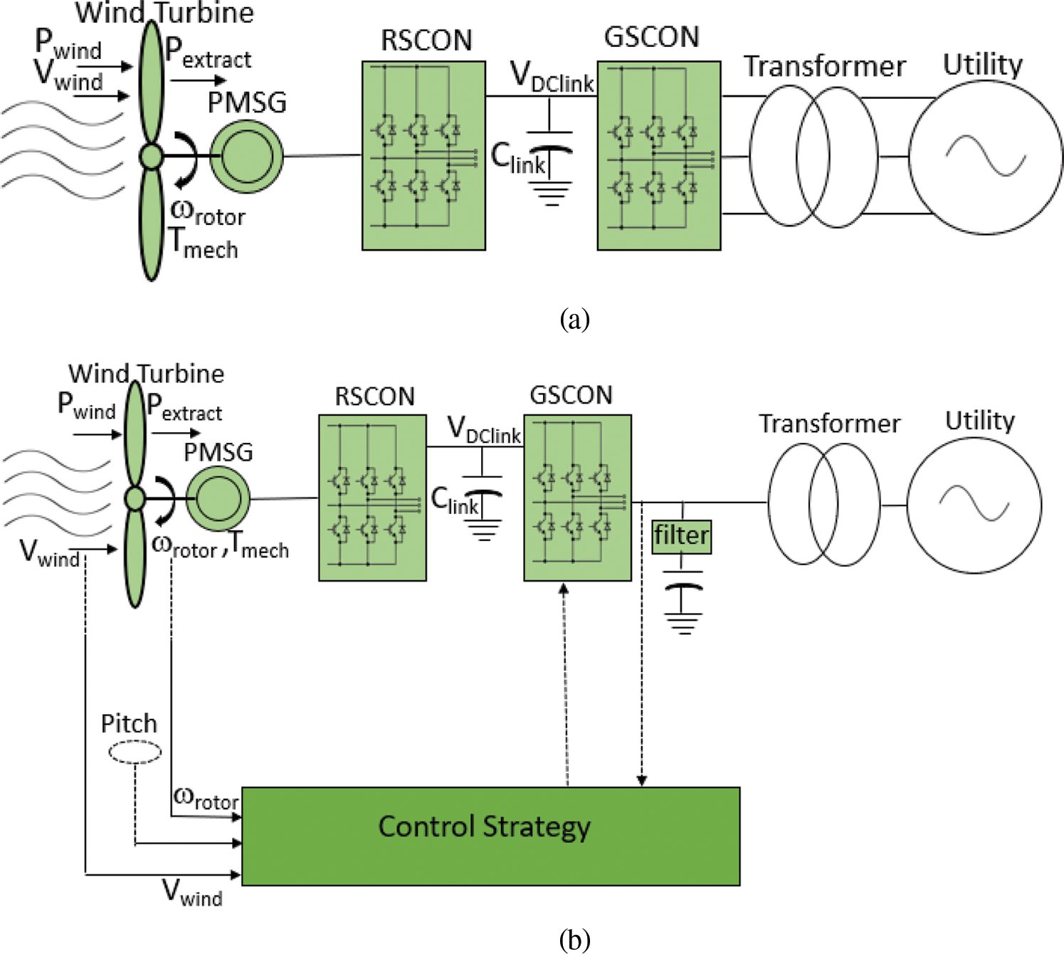
Figure 1: PMSG based WECS under study. (a) Topology (b) Control strategy
Both RSCON and GSCON are two level-controlled voltage source converters (VSC) which make use of back-to-back space PWM to improve MPPT, and by adjusting d and q axes current, which decouples control of active and reactive power. To enhance the performance of controller, PSO based PI controller is implemented.
Conversion of wind power (
where
where
where
Fig. 2 gives the relationship prevailing between
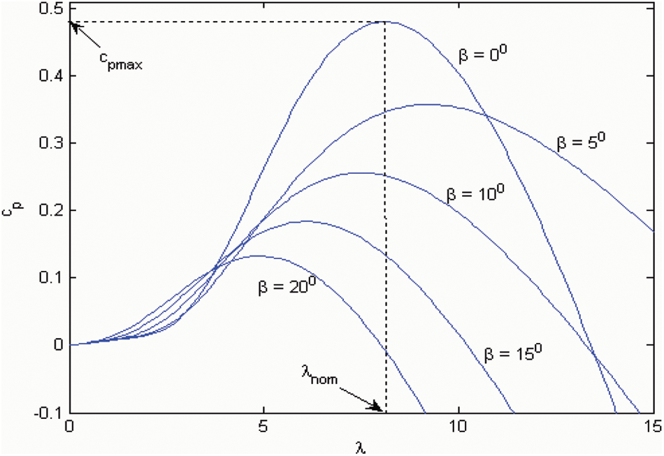
Figure 2: Illustration of
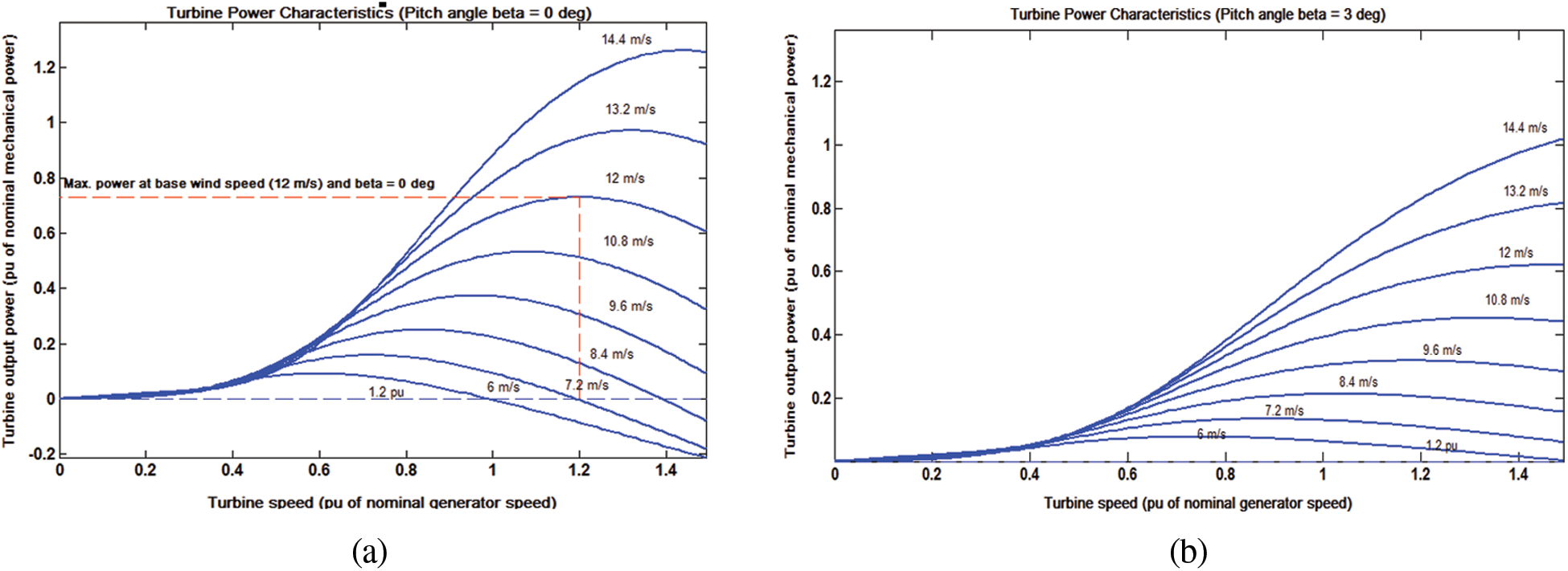
Figure 3: Illustration of
Different control strategies are employed for different wind speed. If the wind speed higher than the cut in speed of wind and lower than rated value, then the MPPT algorithm maximize the
The PMSG modeling is based on d-q axis coordinates of DC stator voltage and current. Eqs. (6)–(7) represent the current flowing in stator winding along d-q axis.
where
The electromagnetic torque produced by PMSG is given by Eq. (10).
where
When the wind speed
The function of RSCON is the maximum conversion of wind energy to electrical power. It is evident from Eq. (10), that to control
where
Fig. 4 shows the schematic diagram of RSCON controller. The error between
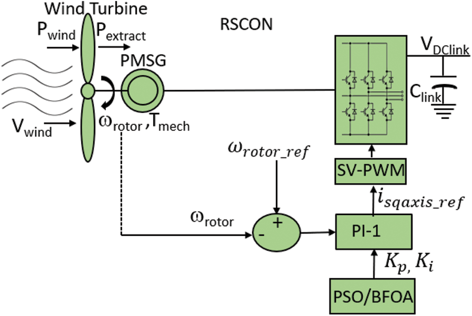
Figure 4: Schematic Diagram of RSCON Controller
Modeling of GSCON includes DC link capacitor and 3 phase voltage source converters. Eqs. (13), (14) represents the voltage balance equation across the filter along d-q axis [37].
where
The instantaneous real and reactive power injected from GSCON to utility grid has direct dependence on
and the steady state real and reactive power injected from GSCON to utility grid has direct dependence on
where
GSCON controller serves two purposes namely maintaining stable DC link voltage [38] and controlling active and reactive power [39]. Using Eqs. (13) and (14), the values of
Like RSCON controller, in GSCON also PI controller 2 (PI-2) controls the inner current loop. The error signal between
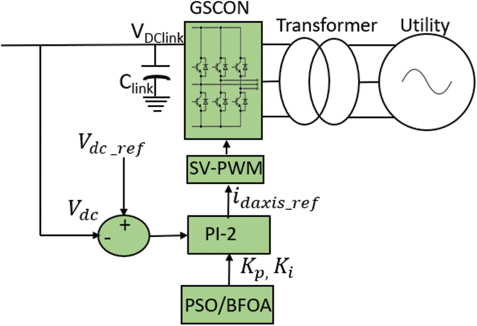
Figure 5: Schematic Diagram of GSCON Controller
3.1 Particle Swarm Optimization Algorithm
In this section, PSO a population search algorithm is used as an optimization tool in which individual’s particles varies its state with respect to time in multi-dimensional search space. In each iteration, every particle achieves
This particle makes use of velocity concept for updation and modified velocity at each iteration is given by Eq. (19) and position of each particle is updated using Eq. (20).
where
The inertia weight used in this work is given by Eq. (21) [40].
where
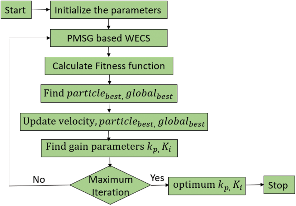
Figure 6: PSO based approach to find optimal gain parameters of PI controller
3.2 Bacterial Foraging Algorithm
A prokaryotic unicellular Echerichia coli (E.coli) bacteria’s food combing and foraging behavior, is evaluated as optimization algorithm, known as the bacterial foraging (BFOA) algorithm, introduced by Passino [42]. Size of chemotactic step is varied on each run depending on fitness value. In general, the algorithm not only believes the chemotactical plan. In continuation to that, their behaviors depend on elimination and dispersal, reproduction, and swarm.
4 Simulation Results and Discussion
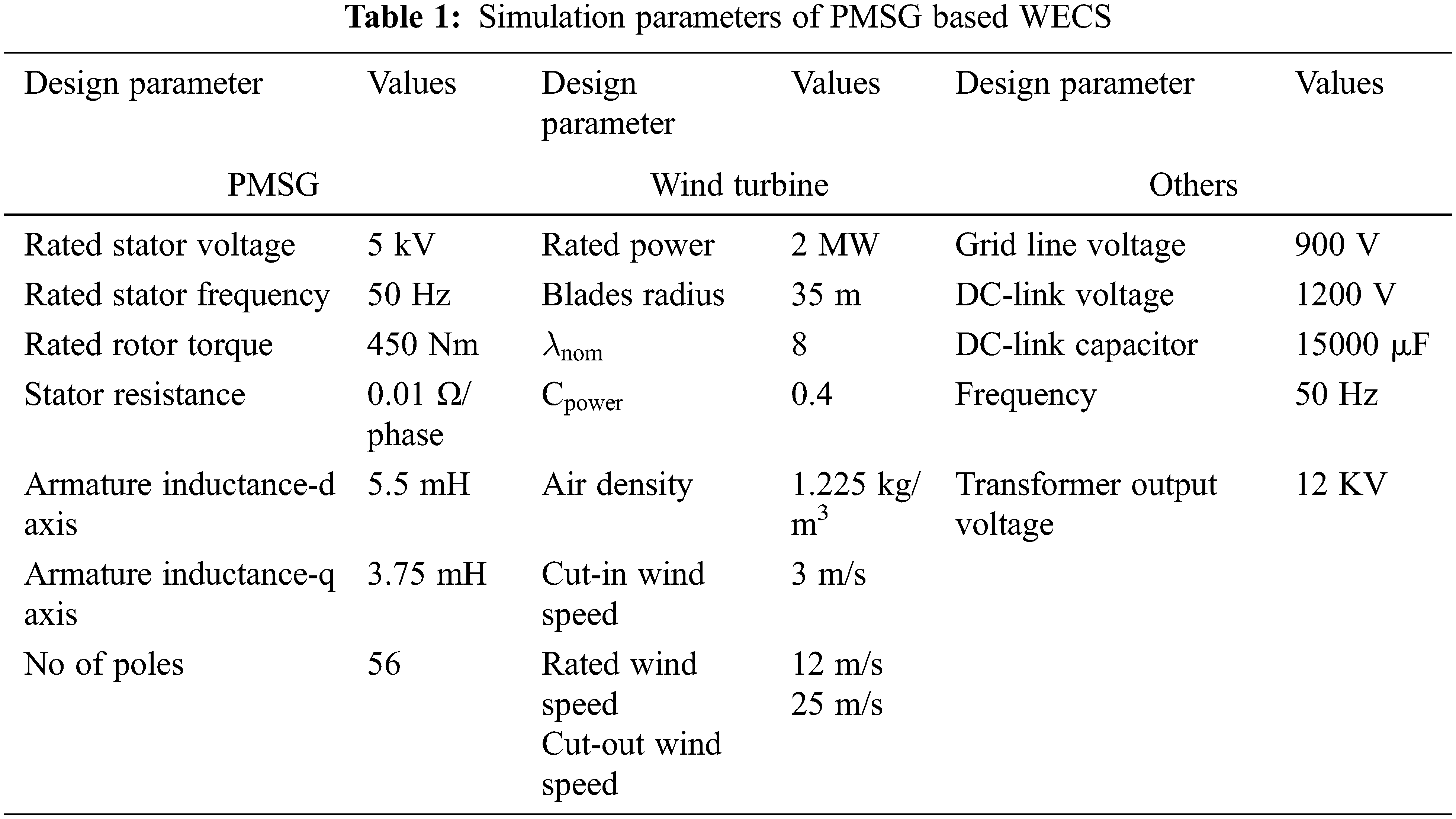
The PMSG based WECS simulation work has been carried out in MATLAB 2020b is used to simulate this system design in Fig. 1. The wind turbine in PMSG based WECS provide the optimum wind speed as reference quantity to control management by obtaining the wind speed. The parameters used in this work for design consideration are listed in Tab. 1.
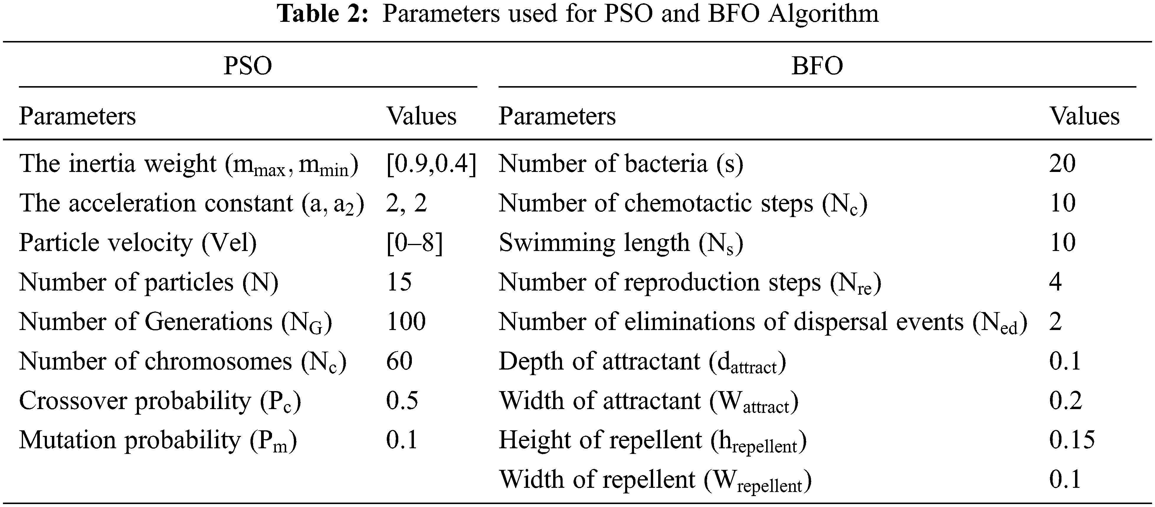
The initial values of all system values are set to zero. The parameter used in PSO and BFOA for finding optimal parameters are listed in Tab. 2. Through MPPT, PAC produces
To evaluate the performance of PMSG based wind turbine in WECS with PSO control strategy four different cases are considered. Case (i) Constant wind with
4.1 Case (i)-Simulation Results
Fig. 7 shows the simulation results of speed, torque, stator voltage and current of PMSG in WECS.
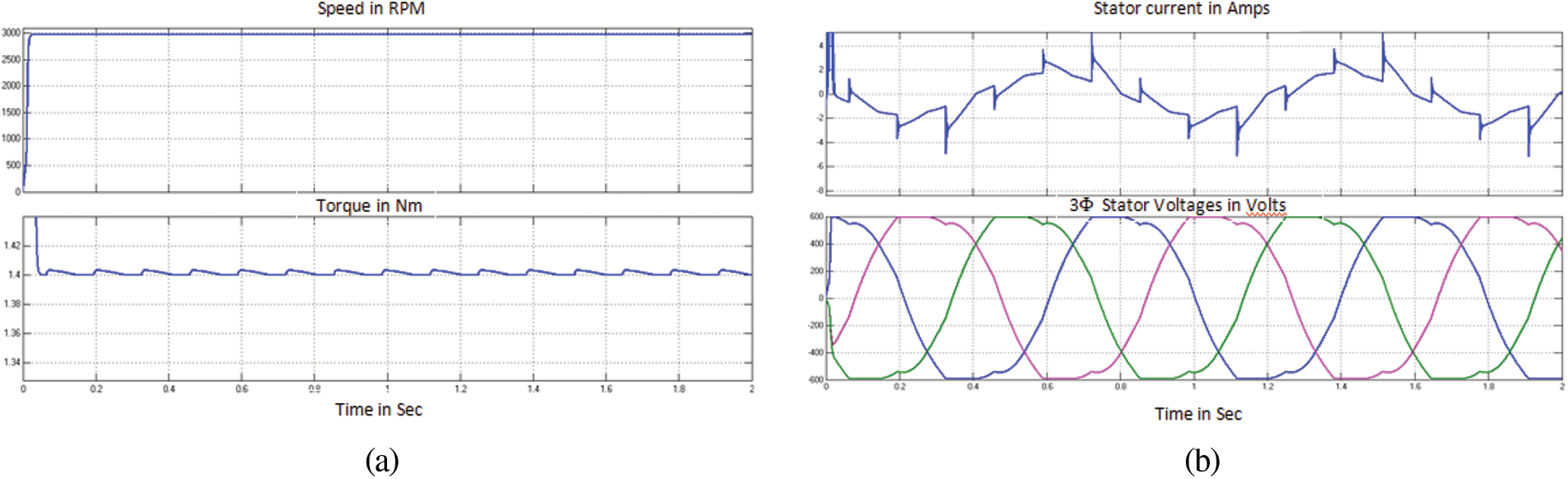
Figure 7: Performance Curves of PMSG in WECS for Case (i) (a) Mechanical Characteristics (b) Electrical Characteristics
Fig. 8 shows the dc link voltage waveform, modulated output voltage and 3 phase outputs fed to grid. From result it is evident that PMSG in WECS gives stabilized output without any fluctuation. Fig. 9 shows the modulation index and output current wave forms PMSG bases WECS for case (i).

Figure 8: GSCON Performance curves of PMSG in WECS for Case (i)
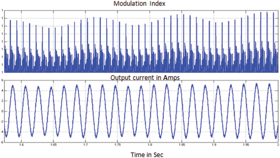
Figure 9: Modulating signal of GSCON and output current fed to grid for Case (i)
4.2 Case (ii)-Simulation Results
Fig. 10 shows the simulation results of speed, torque, stator voltage and current of PMSG in WECS for case (ii). Disturbance arises at 1 s due to change in wind speed.
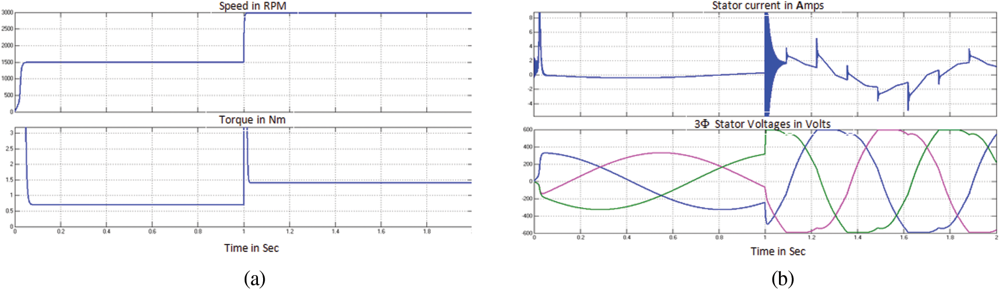
Figure 10: Performance curves of PMSG in WECS for case (ii) (a) Mechanical characteristics (b) Electrical characteristics
Fig. 11 shows the dc link voltage waveform, modulated output voltage and 3 phase outputs fed to grid. There is a fluctuation in wind velocity at 1 s, GSCON makes it control to produce stabilized results. From result it is evident that PMSG in WECS gives stabilized output without any fluctuation. Fig. 12 shows the modulation index and output current wave forms PMSG bases WECS for case (ii).
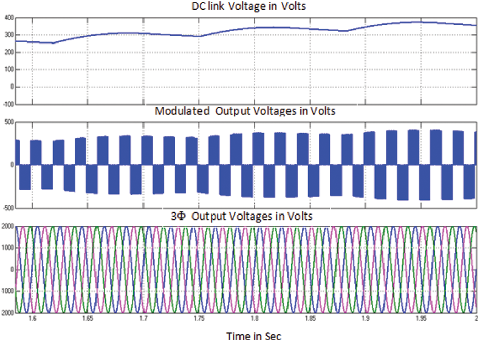
Figure 11: GSCON performance curves of PMSG in WECS for case (ii)
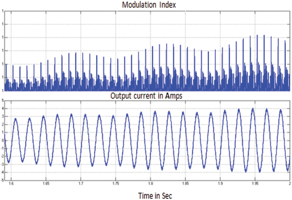
Figure 12: Modulating signal of GSCON and output current fed to grid for case (ii)
4.3 Case (iii)-Simulation Results
Fig. 13 shows the simulation results of speed, torque, stator voltage and current of PMSG in WECS for case (iii). Fig. 14 shows the dc link voltage waveform, modulated output voltage and 3 phase outputs fed to grid. From result it is evident that PMSG in WECS gives stabilized output without any fluctuation. Fig. 15 shows the modulation index and output current wave forms PMSG bases WECS for case (iii).
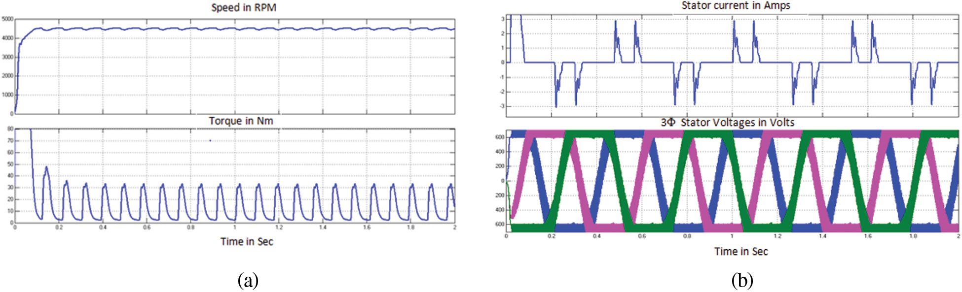
Figure 13: Performance curves of PMSG in WECS for case (iii) (a) Mechanical characteristics (b) Electrical characteristics
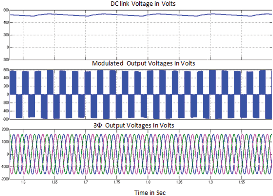
Figure 14: GSCON performance curves of PMSG in WECS for case (iii)
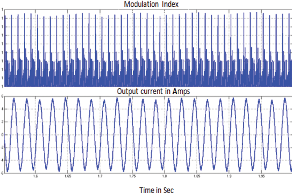
Figure 15: Modulating signal of GSCON and output current fed to grid for case (iii)
4.4 Case (iv)-Simulation Results
Fig. 16 shows the simulation results of speed, torque, stator voltage and current of PMSG in WECS for case (iv). Similar to case (ii), wind speed varies at 1s. with GSCON, the output waveforms are regulated.
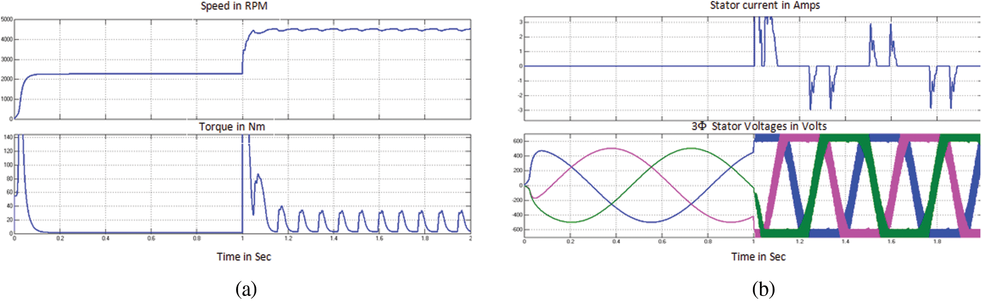
Figure 16: Performance curves of PMSG in WECS for case (iv) (a) Mechanical characteristics (b) Electrical characteristics
Fig. 17 shows the dc link voltage waveform, modulated output voltage and 3 phase outputs fed to grid. From result it is evident that PMSG in WECS gives stabilized output without any fluctuation. Fig. 18 shows the modulation index and output current wave forms PMSG bases WECS for case (iv).
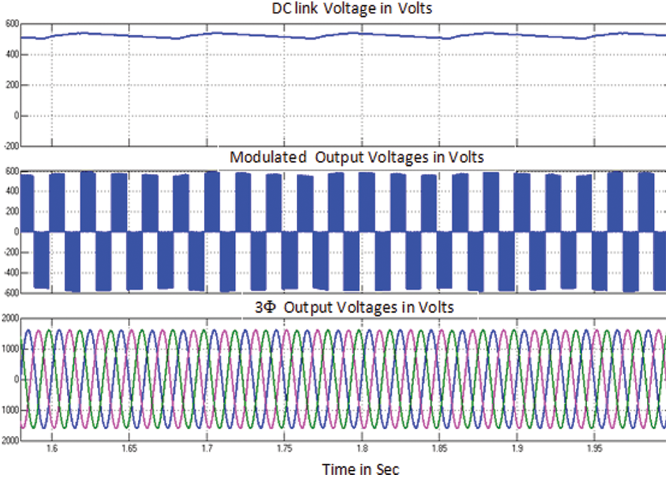
Figure 17: GSCON performance curves of PMSG in WECS for case (iv)

Figure 18: Modulating signal of GSCON and output current fed to grid for case (iv)
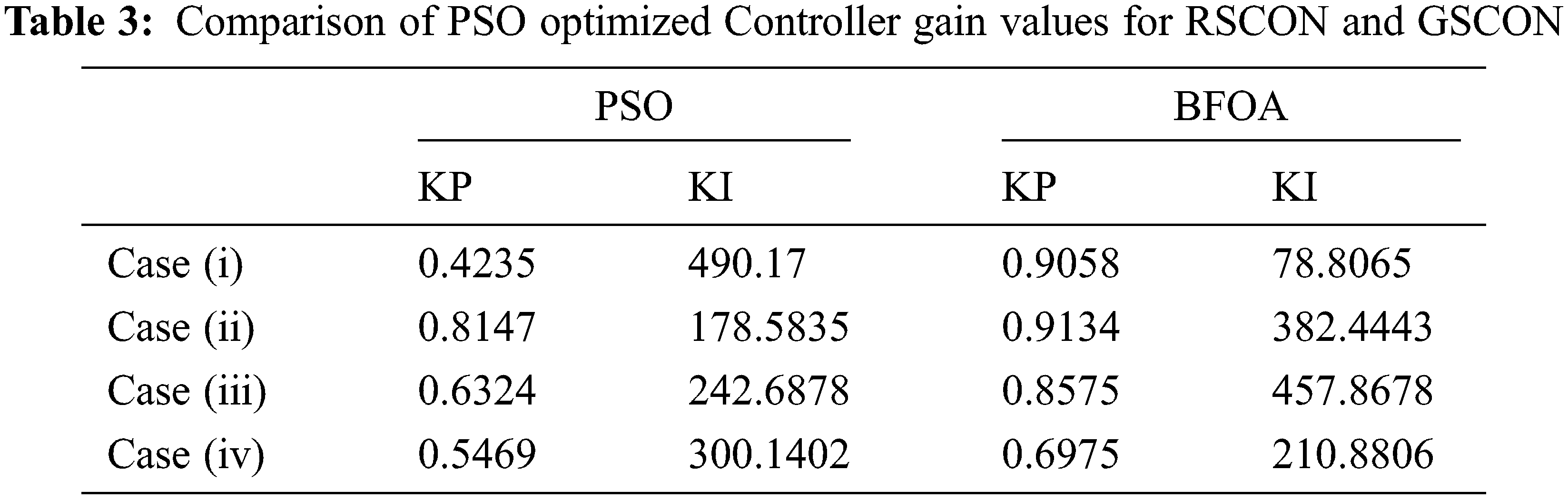
From simulation results, irrespective of changes in wind velocity the current through d axis is maintained at zero level. Tab. 3 shows the controller gain values optimized by PSO/BFOA for RSCON and GSCON controllers. With these gain values the PMSG based WECS able to deliver the stable output power to the grid are rated voltage, frequency, and phase.
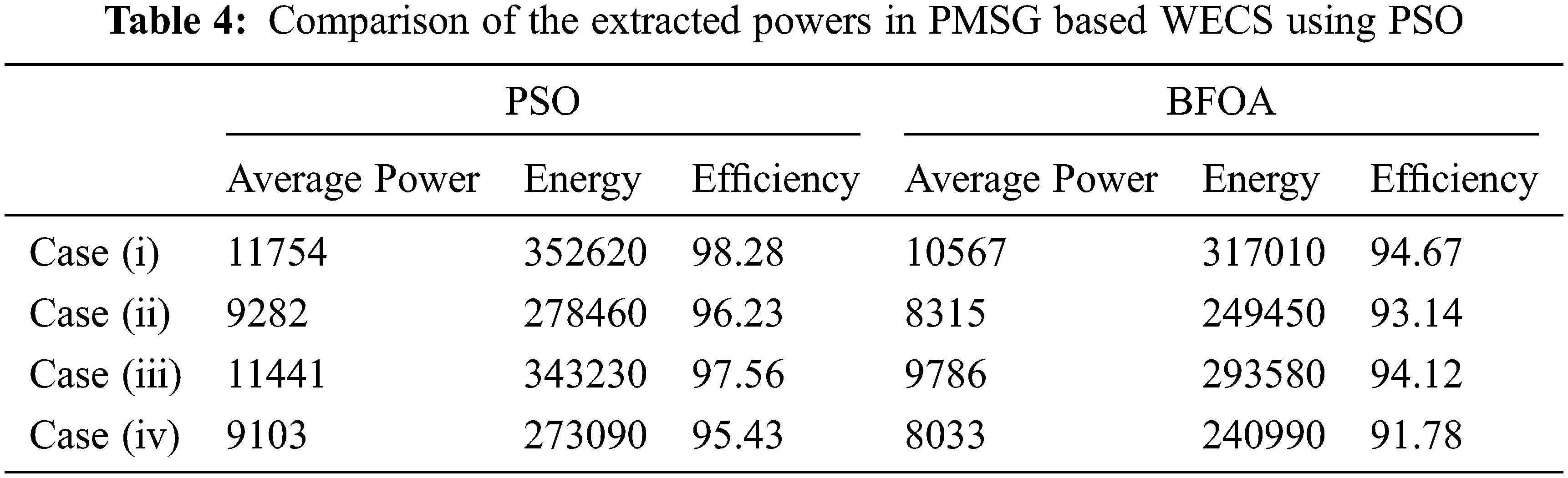
Besides, Tab. 4 provides the comparison of the data related to extracted average power, corresponding energy and efficiency for the two optimization techniques namely PSO and BFOA. It is evident from the table, the efficiency of PSO based optimization reaches a maximum of 98.28% for case (i) and also the efficiency is higher for all the cases compared to BFOA. With the aid of this PSO based autonomous control done through PAC, RSCON, and GSCON, PMSG based WECS to achieve the maximum efficiency.
In this work, PMSG based WECS using PSO for optimization with MPPT and PI controllers are modeled, designed and simulated the whole system to deliver power to grid in MATLAB Simulink 2020b environment. PAC controller tracked by MPPT, RSCON and GSCON controller with optimum gain parameters identified by PSO shows combined effect in achieving static and dynamic performance of PMSG based WECS. The performance of the proposed system has been compared with BFOA based system. The proposed model tracks the maximum power and operated the PMSG based wind turbine at high efficiency. DC link voltage is also stable for active and reactive power decoupling, and grid supply voltage and current are kept constant irrespective of change in wind velocity and pitch angle and thereby guarantee the optimum power supply to grid.
Acknowledgement: The authors would like to acknowledge the management, director, principal and Head of EEE Department of National Engineering College for having provided facilities to carry out the research work.
Funding Statement: The authors received no specific funding for this research work.
Conflicts of Interest: The authors declare that they have no conflicts of interest to report regarding the current research work.
1. P. Li, J. Wang, F. Wu and H. Li, “Nonlinear controller based on state feedback linearization for series-compensated DFIG-based wind power plants to mitigate sub-synchronous control interaction,” Inernational Transactions on Electrical Energy Systems, vol. 29, no. 1, pp. 1–23, 2018. [Google Scholar]
2. J. M. Mauricio, A. Marano, A. G. Exposito and J. L. M. Ramos, “Frequency regulation contribution through variable-speed wind energy conversion systems,” IEEE Transactions on Power Systems, vol. 24, no. 1, pp. 173–180, 2009. [Google Scholar]
3. A. Uehara, A. Pratap, T. Goya, T. Senjyu, A. Yona et al., “A coordinated control method to smooth wind power fluctuations of a PMSG-based WECS,” IEEE Transactions on Energy Conversion, vol. 26, no. 2, pp. 550–558, 2011. [Google Scholar]
4. J. Yana, H. Lina, Y. Fenga and Z. Q. Zhub, “Control of a grid-connected direct-drive wind energy conversion system,” Renewable Energy, vol. 66, no. 5, pp. 371–380, 2014. [Google Scholar]
5. X. Zhang, Z. Wu, M. Hu, X. Li and G. Lv, “Coordinated control strategies of VSC-HVDC based wind power systems for low voltage ride through,” Energies, vol. 8, no. 7, pp. 7224–7242, 2015. [Google Scholar]
6. S. Li, T. A. Haskew and L. Xu, “Conventional and novel control designs for direct driven PMSG wind turbines,” Electric Power Systems Research, vol. 80, no. 3, pp. 328–338, 2010. [Google Scholar]
7. D. Xie, Y. Lu, J. Sun and C. Gu, “Small signal stability analysis for different types of PMSGs connected to the grid,” Renewable Energy, vol. 106, no. 6, pp. 149–164, 2017. [Google Scholar]
8. I. Serban and C. Marinescu, “A sensorless control method for variable-speed small wind turbines,” Renewable Energy, vol. 43, no. 1, pp. 256–266, 2012. [Google Scholar]
9. K. N. Yu and C. K. Liao, “Applying novel fractional order incremental conductance algorithm to design and study the maximum power tracking of small wind power systems,” Journal of Applied Research and Technology, vol. 13, no. 2, pp. 238–244, 2015. [Google Scholar]
10. V. Yaramasu and B. Wu, “Predictive control of a three-level boost converter and an NPC Inverter for high-power PMSG-based medium voltage wind energy conversion systems,” IEEE Transactions on Power Electronics, vol. 29, no. 10, pp. 5308–5322, 2014. [Google Scholar]
11. S. Nallusamy, D. Velayutham and U. Govindarajan, “Design and implementation of a linear quadratic regulator controlled active power conditioner for effective source utilisation and voltage regulation in low-power wind energy conversion systems,” IET Power Electronics, vol. 8, no. 11, pp. 2145–2155, 2015. [Google Scholar]
12. L. Barote, C. Marinescu and M. N. Cirstea, “Control structure for single-phase standalone wind-based energy sources,” IEEE Transactions on Industrial Electronics, vol. 60, no. 2, pp. 764–774, 2013. [Google Scholar]
13. M. M. R. Singaravel and S. A. Daniel, “MPPT with single DC-DC converters and inverter for grid-connected hybrid wind-driven PMSG-PV system,” IEEE Transactions on Industrial Electronics, vol. 62, no. 8, pp. 4849–4857, 2015. [Google Scholar]
14. B. Yang, T. Yu, H. Shu, D. Qiu, Y. Zhang et al., “Passivity-based linear feedback control of permanent magnetic synchronous generator based wind energy conversion systems: Design and analysis,” IET Renewable Power Generation, vol. 12, no. 9, pp. 981–991, 2018. [Google Scholar]
15. X. Yuan, F. Wang, D. Boroyevich, Y. Li and R. Burgos, “DC-link voltage control of a full power converter for wind generator operating in weak-grid systems,” IEEE Transactions on Power Electronics, vol. 23, no. 9, pp. 2178–2192, 2009. [Google Scholar]
16. Z. Wang and L. Chang, “A DC voltage monitoring and control method for three-phase grid-connected wind turbine inverters,” IEEE Transactions on Power Electronics, vol. 23, no. 3, pp. 1118–1125, 2008. [Google Scholar]
17. G. Escobar, A. M. Stankovic, J. M. Carrasco, E. Galvan and R. Ortega, “Analysis and design of direct power control (DPC) for a three phase synchronous rectifier via output regulation sub-spaces,” IEEE Transactions on Power Electronics, vol. 18, no. 3, pp. 823–830, 2012. [Google Scholar]
18. H. H. H. Mousa, A. R. Youssef and E. E. M. Mohamed, “Hybrid and adaptive sectors P & O MPPT algorithm based wind generation system,” Renewable Energy, vol. 145, pp. 1412–1429, 2020. [Google Scholar]
19. M. Nasiri, J. Milimonfared and S. H. Fathi, “Modeling, analysis and comparison of TSR and OTC methods for MPPT and power smoothing in permanent magnet synchronous generator-based wind turbines,” Energy Conversion and Management, vol. 86, no. 2, pp. 892–900, 2014. [Google Scholar]
20. B. Yang, T. Yub, H. Shua, X. Zhangc, K. Qub et al., “Democratic joint operations algorithm for optimal power extraction of PMSG based wind energy conversion system,” Energy Conversion and Management, vol. 159, no. 5, pp. 312–326, 2018. [Google Scholar]
21. B. Yang, L. Zhong, T. Yu, H. Shu, P. Cao et al., “PCSMC design of permanent magnetic synchronous generator for maximum power point tracking,” IET Generation Transmission and Distribution, vol. 13, no. 14, pp. 3115–3126, 2019. [Google Scholar]
22. J. Lee and Y. Kim, “Sensorless fuzzy-logic-based maximum power point tracking control for a small-scale wind power generation systems with a switched mode rectifier,” IET Renewable Power Generation, vol. 10, no. 2, pp. 194–202, 2016. [Google Scholar]
23. L. Wang, L. Cao and L. Zhao, “Non-linear tip speed ratio cascade control for variable speed high power wind turbines: A backstepping approach,” IET Renewable Power Generation, vol. 12, no. 8, pp. 968–972, 2018. [Google Scholar]
24. X. Yin, Y. Lin, W. Li, Y. Gu, P. Lei et al., “Sliding mode voltage control strategy for capturing maximum wind energy based on fuzzy logic control,” International Journal of Electrical Power and Energy Systems, vol. 70, no. 7, pp. 45–51, 2015. [Google Scholar]
25. B. Yang, T. Yu, H. Shu, Y. Zhang, J. Chen et al., “Passivity-based sliding-mode control design for optimal power extraction of a PMSG based variable speed wind turbine,” Renewable Energy, vol. 119, no. 5, pp. 577–589, 2018. [Google Scholar]
26. L. Yang and J. Yang, “Nonsingular fast terminal sliding-mode control for nonlinear dynamical systems,” Intermnational Journal of Robust Nonlinear Control, vol. 21, no. 16, pp. 1865–1879, 2011. [Google Scholar]
27. M. B. H. Kumar, B. Saravanan, P. Sanjeevikumar and F. Blaabjerg, “Review on control techniques and methodologies for maximum power extraction from wind energy systems,” IET Renewable Power Generation, vol. 12, no. 14, pp. 1609–1622, 2018. [Google Scholar]
28. E. H. Dursun, H. K. Ahmet and A. Kulaksiz, “A novel unified maximum power extraction framework for PMSG based WECS using chaotic particle swarm optimization derivatives,” Engineering Science and Technology, an International Journal, vol. 24, no. 1, pp. 158–170, 2021. [Google Scholar]
29. M. Cheng and Y. Zhu, “The state of the art of wind energy conversion systems and technologies: A review,” Energy Conversion and Management, vol. 88, no. 2, pp. 332–347, 2014. [Google Scholar]
30. M. Yin, W. Li, C. Y. Chung, L. Zhou, Z. Chen et al., “Optimal torque control based on effective tracking range for maximum power point tracking of wind turbines under varying wind conditions,” IET Renewable Power Generations, vol. 11, no. 4, pp. 501–510, 2017. [Google Scholar]
31. J. Castelló, J. M. Espí and R. G. Gil, “Development details and performance assessment of a wind turbine emulator,” Renewable Energy, vol. 86, no. 5, pp. 848–857, 2016. [Google Scholar]
32. M. A. Abdullah, T. A. Hadhrami, C. W. Tan and A. H. Yatim, “Towards green energy for smart cities: Particle swarm optimization based MPPT approach,” IEEE Access, vol. 6, pp. 58427–58437, 2018. [Google Scholar]
33. C. Wei, Z. Zhang, W. Qiao and L. Qu, “An adaptive network-based reinforcement learning method for MPPT control of PMSG wind energy conversion systems,” IEEE Transactions on Power Electronics, vol. 31, no. 11, pp. 7837–7848, 2016. [Google Scholar]
34. S. M. Mozayan, M. Saad, H. Vahedi, H. F. Blanchette and M. Soltani, “Sliding mode control of PMSG wind turbine based on enhanced exponential reaching law,” IEEE Transactions on Industrial Electronics, vol. 63, no. 10, pp. 6148–6159, 2016. [Google Scholar]
35. B. Beltran, M. E. H. Benbouzid and T. A. Ali, “Second-order sliding mode control of doubly fed induction generator driven wind turbine,” IEEE Transactions on Energy Conversion, vol. 27, no. 2, pp. 261–269, 2012. [Google Scholar]
36. Z. Zhang, Y. Zhao, W. Qiao and L. Qu, “A discrete-time direct torque control for direct driven PMSG-based wind energy conversion systems,” IEEE Transactions on Industrail Applications, vol. 51, no. 4, pp. 3504–3514, 2015. [Google Scholar]
37. E. Koutroulis and K. Kalaitzakis, “Design of a maximum power tracking system for wind-energy-conversion applications,” IEEE Transactions on Industrial Electronics, vol. 53, no. 2, pp. 486–494, 2006. [Google Scholar]
38. S. Li, T. A. Haskew, R. P. Swatloski and W. Gathings, “Optimal and direct-current vector control of direct-driven PMSG wind turbines,” IEEE Transactions on Power Electronics, vol. 27, no. 5, pp. 2325–2337, 2012. [Google Scholar]
39. J. Marques, H. Pinheiro, H. A. Gründling, J. R. Pinheiro and H. L. Hey, “A survey on variable-speed wind turbine system,” Proceedings of the Cientifico Greater Forum of Brazillian Electronics of Power, vol. 1, pp. 732–738, 2003. [Google Scholar]
40. S. Zhang, K. J. Tseng, D. M. Vilathgamuwa, T. D. Nguyen and X. Y. Wang, “Design of a robust grid interface system for PMSG-based wind turbine generators,” IEEE Transactions on Industrial Electronics, vol. 58, no. 1, pp. 316–328, 2011. [Google Scholar]
41. P. L. Mareddy, V. C. V. Reddy and U. R. Vyza, “Optimal DG placement for minimum real power loss in radial distribution systems using PSO,” Journal of Theoritical and Applied Information Technology, vol. 13, no. 2, pp. 107–116, 2010. [Google Scholar]
42. K. M. Passino, “Biomimicry of bacterial foraging for distributed optimization and control,” IEEE Control System Magazine, vol. 22, no. 3, pp. 52–67, 2002. [Google Scholar]
 | This work is licensed under a Creative Commons Attribution 4.0 International License, which permits unrestricted use, distribution, and reproduction in any medium, provided the original work is properly cited. |