DOI:10.32604/iasc.2022.024173
| Intelligent Automation & Soft Computing DOI:10.32604/iasc.2022.024173 | |
| Article |
Enhanced Distributed Storage System Using Lower Triangular Matrix-Luby Transform Codes
Department of Information Technology, Sri Sivasubramaniya Nadar College of Engineering, Kalavakkam, 603110, Chennai, Tamil Nadu, India
*Corresponding Author: Joe Louis Paul Ignatius. Email: joelouisi@ssn.edu.in
Received: 08 October 2021; Accepted: 08 December 2021
Abstract: In today’s digital environment, large volume of digital data is created daily and this data accumulates to unforeseen levels. Industries are finding it increasingly difficult to store data in an effective and trustworthy manner. Distributed storage appears to be the greatest approach for meeting current data storage demands at the moment. Furthermore, due to disc crashes or failures, efficient data recovery is becoming an issue. At present, new data storage techniques are required in order to restore data effectively even if some discs or servers are crashed. Hence, this proposed work aims to improve the storage efficiency and reliability in distributed storage systems (DSSs) to withstand disk failures and data erasures by modifying the degree distribution of Luby Transform (LT) codes. Recently, deriving an optimal degree distribution in LT codes becomes an upcoming research field. Hence, in this work, a novel approach called Lower Triangular Matrix (LTM) based degree distribution is presented for LT encoding. Unlike the traditional schemes such as Robust Soliton Distribution (RSD), there is no need for transmitting the neighbor symbols information along with each and every encoded symbol using LTM-LT codes which results in an efficient utilization of the bandwidth. Further, the overhead of LTM encoder is reduced by performing only one XOR operation for the generation of every new encoded symbol. The performance of LTM-LT codes is evaluated in terms of varying data erasure and disk failure conditions. Simulation results show that the proposed LTM-LT codes perform better compared to the traditional schemes such as RSD used for LT codes in Distributed Storage System.
Keywords: Luby transform (LT) codes; degree distribution; robust soliton distribution (RSD); lower triangular matrix (LTM); LTM-LT codes; distributed storage system
In this section, Luby transform (LT) codes, their characteristics and the encoding and decoding procedures used in LT codes and finally the applications of LT codes in distributed storage systems are briefly presented.
The first practical implementation of Fountain codes were LT codes invented by Luby in 2002 [1,2]. LT codes generate unlimited encoding symbols from the original data. Therefore, LT codes are called as rateless codes [3]. LT codes are simple and efficient [4,5] because the data and the coding symbols are binary in nature, and also encoding and decoding require only bitwise exclusive OR (XOR) operations. Here, encoding symbols can be generated on the fly as few or as many as needed [6]. The combination of encoding symbols is used to recover the original data at the decoder side. In general, the number of encoded symbols needed to recover the original data is slightly large [7]. The encoding symbols can be generated as needed and sent to the decoder in order to recover the original data, therefore the loss of data is not much considered. If the decoder can recover the original data from the minimum combination of possible encoding symbols, then LT codes are near optimal [8] with respect to any erasure channel conditions. The encoding and decoding times in LT codes are closely very efficient as a function of the data length [9]. Therefore, LT codes are near optimal for every erasure channel and they are very efficient as the data length grows [10].
Degree distribution is used to form LT codes such that the decoder can recover the original data from the slightly more coded symbols with high probability [11,12]. In order to recover the original data from the encoding symbols, the decoder needs to know the degree and the source symbols that form the set of neighbors of each encoding symbol [13]. The degree of an encoded block is the number of source blocks involved in the generation of an encoded block. The probability distribution of these degrees over the whole encoded blocks is called as degree distribution where the degree of the coded symbol is chosen at random according to that probability distribution [14,15]. Decoder failure occurs, if the decoder is unable to recover all the original source blocks [16,17].
LT codes provide a huge variety of data delivery applications. It is more applicable for one-to-one data delivery than one-to-many data delivery due to large number of feedbacks needed to be sent by the receivers to the sender thereby consuming more bandwidth and delay. Also, there is a variety of applications of LT codes including robust distributed storage, delivery of streaming content, delivery of content to mobile clients in wireless networks, peer-to-peer applications and delivery of content along multiple paths to ensure resiliency to network disruptions [18–23]. A distributed storage system can be any of the three types of storage: block, file, or object. Due to the high-performance requirements of block-level storage systems, “distributed data storage” usually refers to a single storage system located in a narrow geographic region. The laws of physics prevent it syncing a system that spans three continents takes too long [24].
For distributed storage systems (DSSs), erasure codes must provide systematic encoding, low repair locality, low encoding/decoding complexity, and minimal decoding/storage overhead. However, the information theoretical constraints have revealed that all of these metrics may need to be carefully balanced against one another. A systematic version of LT/Raptor codes achieving a trade-off between repair complexity and overhead is suggested. Also, repairable Fountain codes have recently been proposed for distributed storage [25]. Many studies have been conducted to address the challenges of data storage reliability in dispersed systems which suggest that erasure coding and replication-based methods might be perfect for ensuring the reliability of distributed data storage systems. Wireless Sensor Networks (WSNs) have long utilised distributed coding, which divides the encoding processes over many nodes [26].
The structure of the paper is organized as follows. Section 2 briefly describes about the related works. In Section 3, the proposed degree distribution scheme using LTM is elaborated. Section 4 presents the performance analysis of LTM-LT codes. Section 5 gives the detailed discussion. Section 6 explains how improved performance can be achieved on DSSs using LTM-LT codes. Finally, Section 7 provides the conclusion and future work.
Generally, two-way communication is used for transmitting data across erasure channels. This includes the sender transmitting the stream of encoded blocks or symbols in the form of packets and the receiver decoding the received packets for recovering the original blocks or symbols. The receiver sends an acknowledgment back to the sender once all the packets are received. If the packet is not decoded successfully, then the receiver asks the sender to retransmit the packet [27]. The major disadvantage of this two-way communication is, it requires the feedback channel. But, certain applications like video storage and video streaming do not have a feedback channel over the Internet. Hence, it may not be suitable for those applications [28]. In addition, the two-way communication also consumes more bandwidth and requires more time [29]. The limitations of two-way communication can be overcome by using LT codes especially for the networks with no feedback by adopting an essentially one-way communication protocol. The following are the steps involved during the encoding and decoding processes in LT codes. The sender sends the encoded packets with packet information. The receiver evaluates each received packet. If any error is found, the packet is discarded. Once the receiver has enough number of packets to recover the entire source blocks, the decoder starts decoding [30]. Here, the degree distribution plays a major role in LT codes deciding the time delay factor, bandwidth consumption and many other factors such as decoding efficiency in LT codes [31].
In LT codes, the degree d of an encoding block is chosen randomly [32] so that the number of encoded blocks generated in the encoder will also be in random. The main disadvantage of conventional LT codes is that the average degree of the encoding symbol cannot be determined as the degree is chosen randomly. Moreover, the average degree may sometimes be larger value and sometimes smaller value. If the average degree of the encoding symbol is a larger value, more time is required for the decoder to decode as well as the complexity of the decoder will increase [33]. An exhaustive search strategy to create deterministic LT codes that could be employed in distributed storage systems to correctly decode the original data content. However, based on Plank and Thomason’s findings, it’s unclear whether the exhaustive search technique will be effective or even correct. Therefore, a theoretical investigation of the feasibility and performance difficulties associated with applying LT codes to distributed storage systems has been conducted [34].
From the initial work of Luby, the inventor of LT codes, it is inferred that the degree distribution used in encoder plays a vital role on the performance of LT codes. To achieve the improved performance of LT codes over erasure channels, various degree distribution approaches have been already proposed in the literature. The performance of LT codes with different degree distributions like robust soliton distribution (RSD), suboptimal degree distribution and scale-free (SF) Luby distribution was analyzed in the related works. It was shown that, all the above three-degree distribution-based LT codes were able to recover the source blocks efficiently. SF degree distribution-based LT codes perform better in terms of average degree where large number of encoded blocks has higher degree and a small number of encoded blocks with lower degree. Hence, SFLT codes require a smaller number of encoded blocks for the successful recovery of source blocks. Although the average degree and the complexity (that is the number of XOR’s) involved in encoding and decoding operations are less, this type of degree distribution is not satisfactory over channels with high erasures.
2.1 Robust Soliton Distribution
The degree distribution is critical for the LT code’s performance, and in most LT codes studies, the robust Soliton distribution (RSD) is used. RSD has two parameters, c and δ by which the degree distribution may be altered. The influence of these two factors on the mean degree and decoding performance of the LT code from a different perspective. The function of RSD (i.e., RSD(i)) is given by Eq. (1). The extra set of values added to the elements of the mass function of the Ideal Soliton Distribution (ISD) and then standardizing so that the values add up to 1 gives RSD(i) as given below.
The additional real-valued parameter (which is understood as a failure probability) and the constant parameter c are used here. For the Ideal Soliton Distribution (ISD), the predicted value for degree one nodes was 1. The Robust Soliton Distribution raises this predicted value to R, which is a constant provided by Eq. (2).
where,
The limitations of the RSD are as follows. All the neighbours involved in the formation of encoded block are selected randomly in RSD. Sometimes it may lead to the formation of same encoded blocks again if the neighbours are same. RSD based LT codes needs to store degree and neighbours for every encoded block. The decoder is assumed to know the degree of every code symbol and the set of neighbors associated with it. Moreover, it has been observed that RSD’s performance is not always optimal for finite code length, especially when the code length is small.
Recently, deriving an optimal degree distribution in LT codes becomes an upcoming research field. Hence, in this work, a novel approach called lower triangular matrix (LTM) based degree distribution is presented for LT encoding. In order to reduce the number of exclusive OR (XOR) operations, a predefined degree distribution is used in the proposed LTM based encoder. Unlike the traditional schemes such as Robust Soliton Distribution (RSD), there is no need for transmitting the neighbor symbols information along with each and every encoded symbol using LTM-LT code which results in an efficient utilization of the bandwidth. Further, the overhead of LTM encoder is reduced by performing only one XOR operation for the generation of every new encoded symbol.
3 Lower Triangular Matrix (LTM)
The block diagram representation of the proposed LTM-LT codes has been illustrated in Fig. 1. This proposed work introduces a new type of fixed degree distribution using LTM. Here, the number of encoding blocks as well as the neighbor source blocks involved in each encoded block generation will be known to the encoder once the input data is given. The block length of the encoding block for the given data is determined using the procedure described below. Following are the notations used in this work.
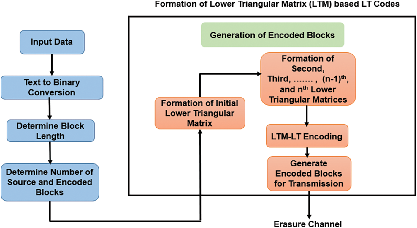
Figure 1: System model of LTM-LT codes
Let the length of the data be k and length of source blocks is represented by total number of source blocks denoted by n and source blocks are represented by bt, where t = 1, 2, …, n. The total number of encoded blocks is denoted by N and each encoded block is denoted by Ebj where j = 1, 2, …, N. Let the degree of the encoded block is denoted by di where i varies from 1 to n.
In LT codes, the very first step is to divide the given input data into some fixed number of blocks known as source blocks or input symbols. In this work, a novel method has been presented for determining the block length, lower triangular matrix-based degree distribution which plays a major role on the performance of LT encoder. Let the total length of the data is denoted by k.
Step 1: Find all the factors of k and arrange them in descending order.
Step 2: Count the total number of factors, let it be c.
Step 3: The third factor starting from the first will be taken as the block length L. By choosing this block length, the number of calculations (XORs) involved in the generation of encoding blocks can be reduced.
Step 4: The total number of XOR’s or complexity X involved is given by Eq. (4),
In RSD based LT codes, the encoded blocks are obtained by XOR operations of several, say i source blocks selected randomly out of n possible source blocks during the coding process. Here, the coding complexity can be described by the number of operations, which equals i − 1. Now, the average number of XOR operations E(i) required for each encoded block can be calculated using R(i) which characterizes the possibility of degree n as given in Eq. (5).
Further, the overhead of LTM encoder is reduced by performing only one XOR operation for the generation of every new encoded symbol. If the factors of k are arranged in an ascending order, the block length L will be too small. Then, the source blocks as well as the encoded blocks will increase which leads into the increase in overhead at encoder and decoder. Here, the third factor is chosen as L in order to get the optimal number of encoded blocks which will decrease the decoder complexity. If the first factor is chosen as L, it resembles like an uncoded system. For a special case, if the data length k is a prime number, then append an extra bit to the data to make k either an even or an odd number so that more than two factors can be possible and then all the blocks will have the same block length. Let us consider the following example. Let k = 20. The factors of k in a decreasing order are 20, 10, 5, 4, 2 and 1. Hence, the number of factors c = 6 and therefore the block length is found as L = 3rd term from the beginning after arranging it in descending order. Hence, L = 5.
3.2 Determining the Number of Source and Encoded Blocks
The total number of source blocks n, involved in the given data is the ratio between the total length of data k and the block length L as given in Eq. (6).
Then, the total number of encoded blocks is found as given in Eq. (7).
The proposed design of fixed degree distribution using LTM for LT codes is described as follows. The minimum degree dmin of the encoded symbol will be 1 and the maximum degree dmax will be n that is the number of source blocks. Note that, the value of dmax for the traditional RSD based LT codes is also n. The only difference is how many numbers of generated encoded blocks is going to have dmax as n in the case of RSD. Then, the corresponding number of encoded blocks of each degree d is illustrated in Fig. 2. It is clearly implicit that the number of encoded blocks of degree 1 is n and number of encoded blocks of degree 2 is n − 1 and so on, where d1 represents encoded blocks with degree 1, d2 represents encoded blocks with degree 2 and dn represents encoded blocks with degree n (that is encoded blocks with maximum degree dmax) as shown in Fig. 2.
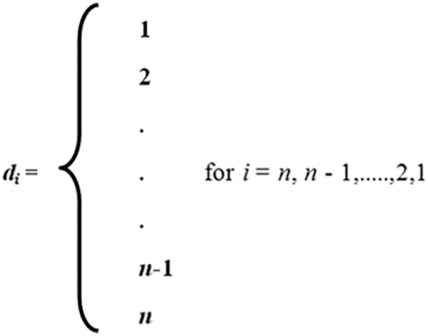
Figure 2: Number of encoded blocks for the given degree
3.3.1 Encoded Blocks Generation
This subsection details about the formation of lower triangular matrix (LTM) for LT codes. First, the initial lower triangular matrix needs to be formed as shown in Fig. 3.
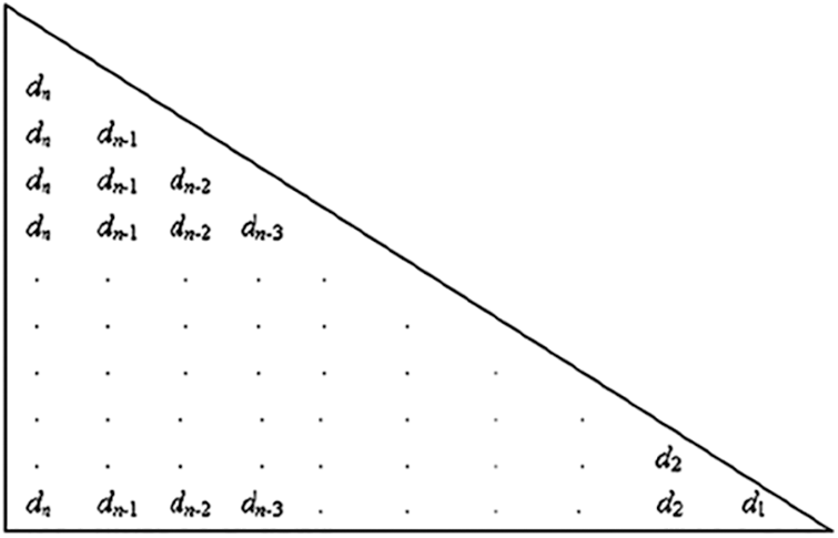
Figure 3: Formation of initial lower triangular matrix
3.3.2 First Lower Triangular Matrix
Let the encoded blocks are represented as Ebj, where j = 1, 2, …,, N. Fig. 3 clearly shows that, the first encoded block Eb1 is the block
3.3.3 Second Lower Triangular Matrix
The second lower triangular matrix can be obtained as shown in Fig. 4 by removing the first column of the initial triangular matrix shown in Fig. 3. The same procedure used in the initial triangular matrix can also be followed for finding the encoded blocks involved in the second lower triangular matrix.
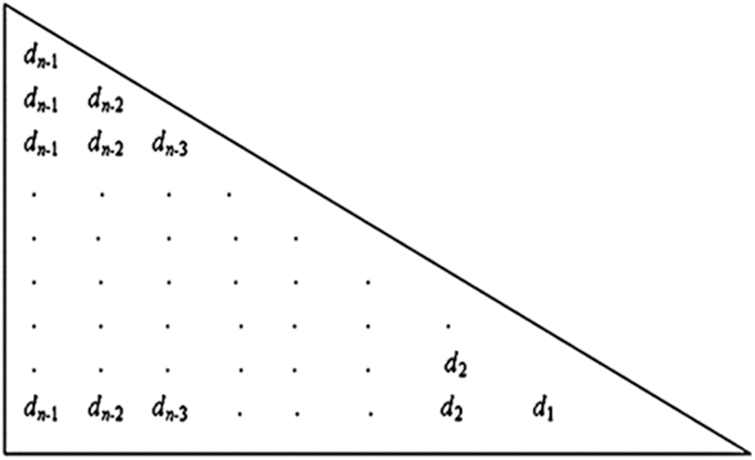
Figure 4: Second lower triangular matrix
3.3.4 (n − 1)th Lower Triangular Matrix
Fig. 5 shows the (n − 1)th lower triangular matrix which consists of only two rows by which the encoded blocks can be generated.
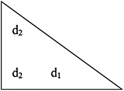
Figure 5: (n − 1)th lower triangular matrix
3.3.5 nth Lower Triangular Matrix
Fig. 6 shows the nth lower triangular matrix which consists of only one element d1. This d1 element forms the only one encoded block that is the last source block bn itself as given in Eq. (9).
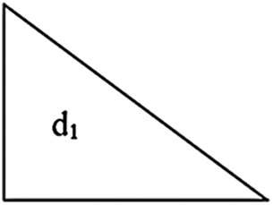
Figure 6: nth lower triangular matrix
Fig. 7 illustrates the histogram of LTM based degree distribution proposed in this work. The input format to the LTM-LT encoder is text. Characters are used to make words and phrases in text. These characters are converted to binary by using an American Standard Code for Information Interchange (ASCII) value. Once the ASCII value is known, it will be converted into binary which is an 8-bit code.
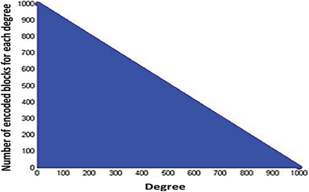
Figure 7: LTM based degree distribution
The histogram clearly states that the number of degree 1 encoded blocks are 1000 and the number of encoded symbols with degree as 1000 is zero. This is the significant advantage of the LTM-LT codes. In the existing RSD based LT codes, the maximum degree dmax of an encoded block can be the number of source blocks itself (1000) which involves 999 (i.e., 1000–1) XOR operations as the maximum which is the complexity of the state-of-art degree distribution-based LT Codes. Let the given data length k = 100000, then the block length L is determined as 100. Hence, the number of source blocks n becomes as 1000 by using Eqs. (6) and (7). Hence, the degree of encoding blocks varies between 1 and 1000. Fig. 7 shows the distribution of degree of the overall encoded symbols generated using the LTM based degree distribution.
3.3.6 A Toy Example for LTM-LT Codes
The important characteristics of LTM-LT codes are as follows.
• the size of the encoded file is less when compared to size of the encoded file which is generated by RSD.
• no need to store the degree and neighbours involved in generation of each encoded block.
• all the encoded symbols are unique.
• since data is encoded and saved, it is highly secure.
Let the message to be encoded using LTM-LT codes is 100011011001111110001101 where the length of the message is 24. Let consider the block length be 6. Now, the message is divided into source blocks with equal block length as 6 as b1 = 100011, b2 = 011001, b3 = 111110, and b4 = 001101. A toy example is illustrated in Fig. 8.
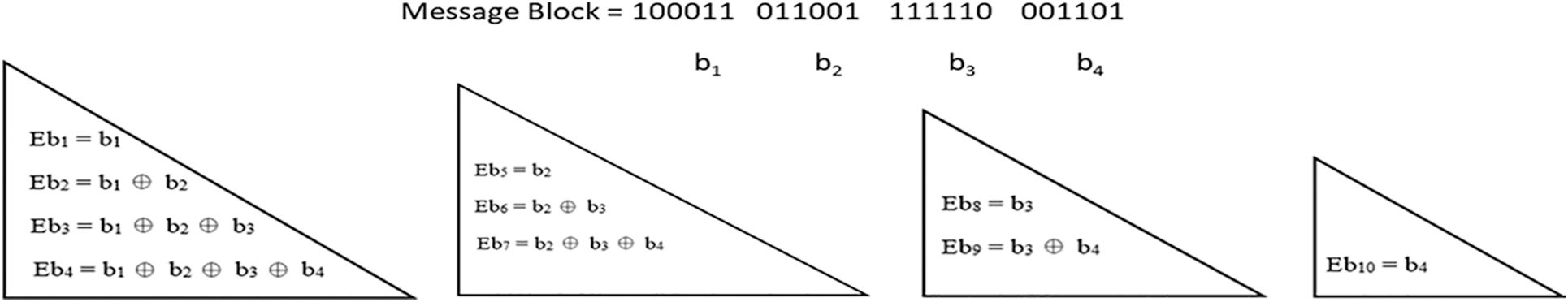
Figure 8: A toy example for LTM-LT Codes
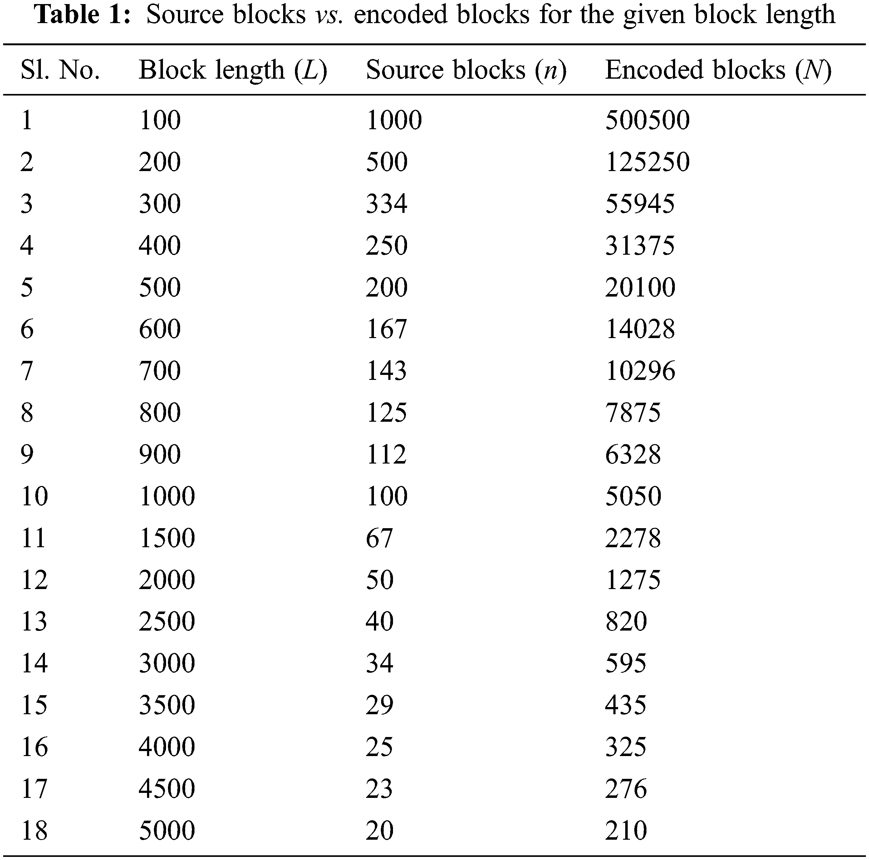
In this work the encoded file generated using LTM is stored in distributed manner. The encoded file formed is shared among 4 disks as shown in Fig. 9. The LTM-LT codes have been simulated using Java. The total number of input bits, the data length k has been considered as 100000, and the erasure probability is taken as zero. For a given input of fixed size, if the length of each block is increased, then the number of source blocks decreases according to the formula proposed in Eq. (6) and due to the decrease in the number of source blocks, the number of encoded blocks will also be decreased according to the proposed algorithm in Section 3. Hence, the block length is inversely proportional to the number of source blocks as well as the number of encoded blocks. By varying the block length L, the corresponding number of source blocks n and the required number of encoded blocks N are tabulated as shown in Tab. 1 by using Eqs. (6) and (7) described in Section 3.
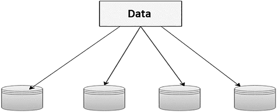
Figure 9: Distributed storage
The main advantage of LTM-LT codes is that there is no need to send explicitly the degree and the neighbor blocks that are involved in the generation of each encoded block irrespective of the erasure probability. Hence, the modified decoder algorithm using the same LTM used in LT encoder has been proposed for decoding. Therefore, it is enough to send the total data length k alone to the decoder which will compute the block length, the degree and the neighbor blocks involved in the encoded blocks automatically by using the same principle LTM used in LT encoder when erasure probability is zero.
If the erasure probability is greater than zero, then the decoder will make use of the unique block id received along with each encoded block for constructing LTM. Whatever may be the erasure channel probability, if the decoder received the first n encoded blocks that is the encoded blocks formed from the initial or first lower triangular matrix, then these received encoded blocks itself are well enough for the decoder to recover the entire source blocks. Since the logic used in encoder and decoder are same, the decoder can easily generate the degree and neighbor array of source blocks for the corresponding received encoded block. When compared with the conventional LT codes, LTM-LT codes result in the usage of very less bandwidth. This approach is clearly explained in Section 5. The following Fig. 10 illustrates the relationship between the block length and source blocks according to the proposed LTM algorithm.
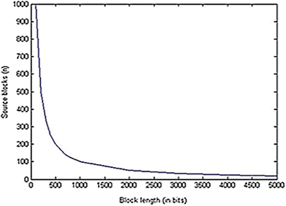
Figure 10: Block length vs. source blocks
From Fig. 10, it is clearly found that for the increase in block length, the number of source blocks is getting decreased. Likewise, the number of encoded blocks is getting decreased for the increase in block length as shown in Fig. 11. Figs. 10 and 11 clearly prove that the number of source blocks as well as the number of encoded blocks’ block length is inversely proportional to the block length. The relationship between the source blocks and the encoded blocks is described in Fig. 12.
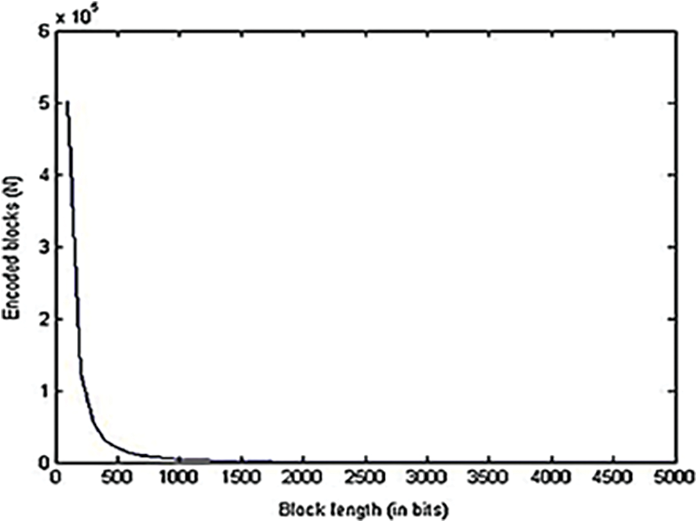
Figure 11: Block length vs. encoded blocks
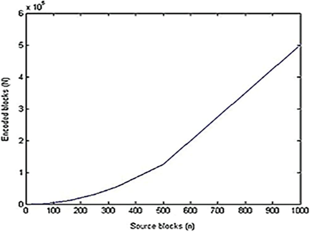
Figure 12: Source length vs. encoded blocks
From Fig. 12, it is clearly noted that, a greater number of source blocks implies that a greater number of encoded blocks needed for transmission of data which consumes more redundancy, bandwidth, encoder and decoder logic times and increases the complexity of the system but at the same time, it may help the decoder to recover all source blocks successfully. In this work, the performance of LMT-LT codes are analyzed for given data using larger block length L by the means of encoder and decoder logic time and decoding efficiency. Here, the given block length L varies between 1000 and 5000 where k = 100000.
Tab. 2 describes the performance of LTM-LT codes in terms of encoder and decoder delay and the block length as the metrics.
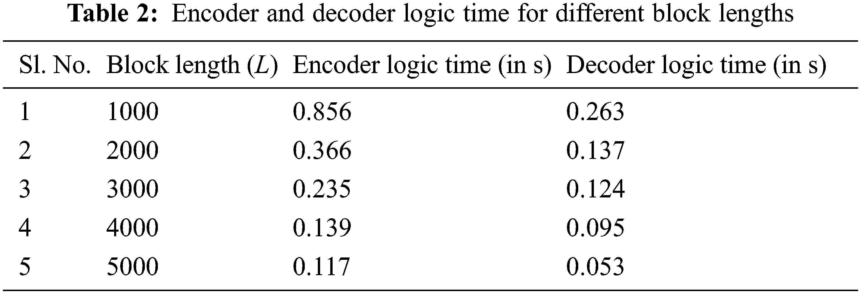
Fig. 13 illustrates that the encoder logic time decreases with the increase in the block length. This is because of the decrease in the number of source blocks n as the block length L increases. Therefore, the number of encoded blocks N gets decreased. As similar like encoder logic time shown in Fig. 13, the decoder logic time also decreases with the increase in the block length as shown in Fig. 14. By comparing the performance of LTM-LT codes shown in Figs. 13 and 14, it is inferred that decoder logic time has smaller values than encoder logic time. This is because of the encoder has to generate the encoded blocks with all the possible combinations. But the decoder need not process all the encoded blocks. Once it recovers all the source blocks, the decoder gets terminated. The following Fig. 15 describes the performance of LTM-LT codes in terms of decoding efficiency as the metric for the given erasure probability varies between 0.1 and 0.8 and the block length as 1000.
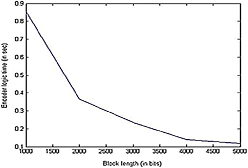
Figure 13: Encoder logic time vs. block length
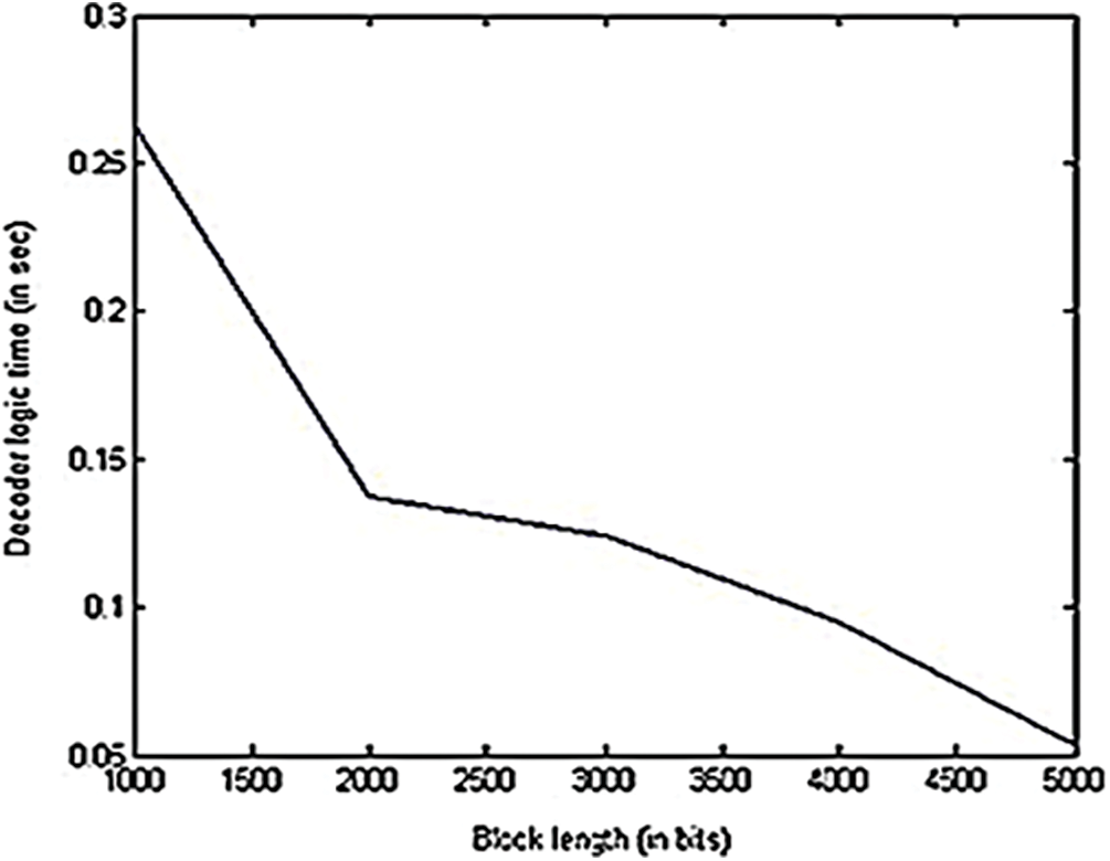
Figure 14: Decoder logic time vs. block length
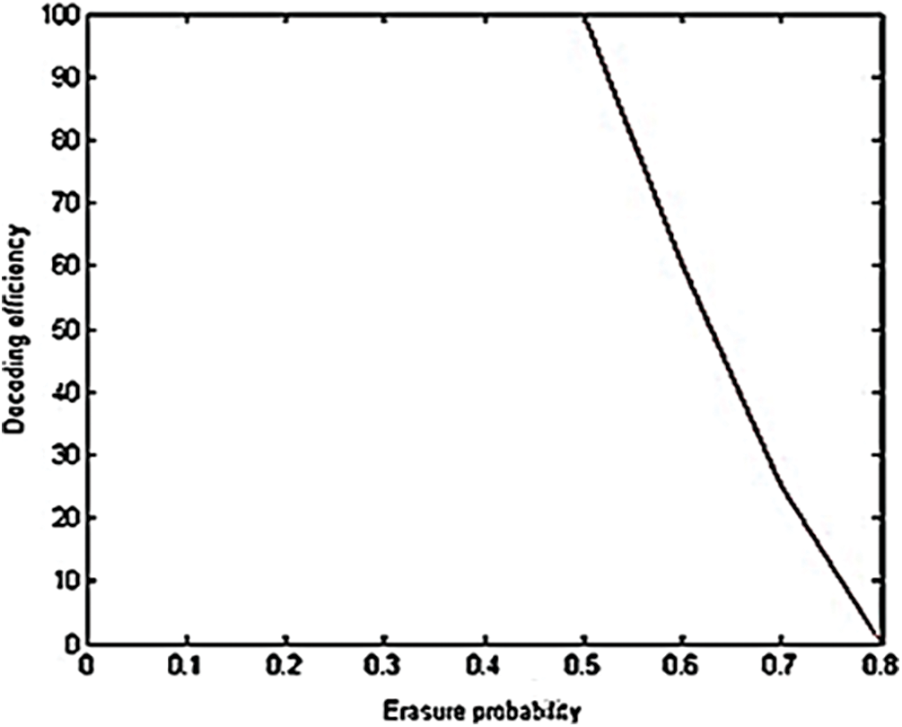
Figure 15: Decoding efficiency vs. erasure probability
Form Fig. 15, it is inferred that for fixed message length and block length and variable erasure probability, the decoding efficiency of 100% can be achieved using the proposed LTM-LT codes for erasure probability up to 0.5. After that the decoding efficiency is decreasing at a constant rate. Hence, erasure probability and decoding efficiency are inversely proportional to each other after the erasure probability 0.5. Following are some of the observations from the performance analysis of LTM-LT codes.
■ Decoding efficiency is directly proportional to the number of source blocks.
■ Decoding efficiency is directly proportional to the number of encoded blocks.
■ Decoding efficiency is inversely proportional to block length
■ Decoding efficiency is inversely proportional to erasure probability of the channel.
For the given message length k = 100000 bits and the block length L as 1,000, the proposed LTM-LT codes will result in 100 source blocks which leads to 5050 encoded blocks. Hence, using the proposed LTM-LT codes 100% recovery of source blocks can be possible even at the erasure probability of 0.9. For the given probability of erasure as 0.9, the number of received encoded blocks (REB) out of 5050 transmitted encoded blocks (EB) collected at the destination is 0.9 × 5050. That is 4545 which is more than enough to recover the original source blocks of 100. Hence, the proposed LTM-LT codes achieve the decoding efficiency of 100% at the erasure probability of 0.9 which is the significant advantage of the proposed work.
5.1 Minimum Number of XOR Operations are Used in LTM–LT Codes
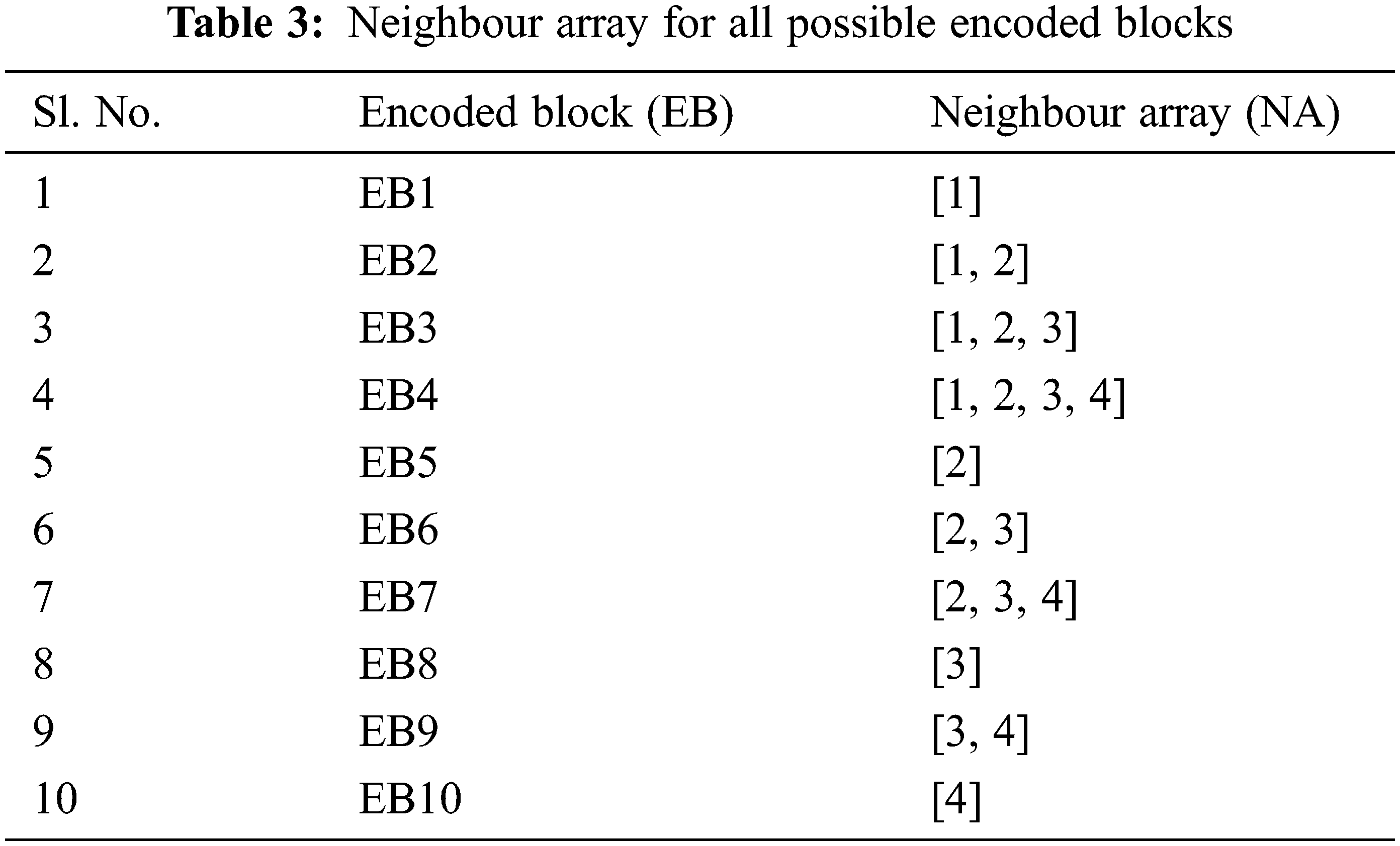
The number of source blocks is fixed as eight, taking into consideration the ASCII length of each character. So, by dividing the total length of data by eight we can get the block length of each block. The total number of encoded blocks is calculated using the formula N = (n(n + 1)/2). There will be 10 encoded blocks if n = 4. In the encoding process, let us consider SB = Source Block and EB = Encoded Block,
The NA of EB1 is [1].
The NA of EB2 is [1, 2].
The NA of EB2 is [1, 2, 3].
The NA of EB4 is [1, 2, 3, 4].
The same procedure can be continued till all the encoded blocks are generated as described in Tab. 3. It can be seen that at any point of time, for the generation of a new encoded block, at most the LTM-LT encoder will be performing only a “single XOR operation” at every stage for the generation of an EB. This is a major advantage of LTM-LT codes which helps in reducing the time taken for encoding the source blocks and also the overhead of the encoder.
The above process can be implemented in the decoding process too. Take any two blocks with consecutive block ids in any Lower Triangular Matrix and perform XOR operation to recover the source block. Let us consider REB = Received Encoded Block, RSB = Recovered Source Block,
So, the NA of RSB1 is [1].
After XOR, the NA of RSB2 is [2]. So, the SB2 (that is Source Block 2) is recovered.
After XOR, NA of RSB3 = [3]
So, the SB3 (that is Source Block 3) is recovered.
After XOR, NA of RSB4 = [4]
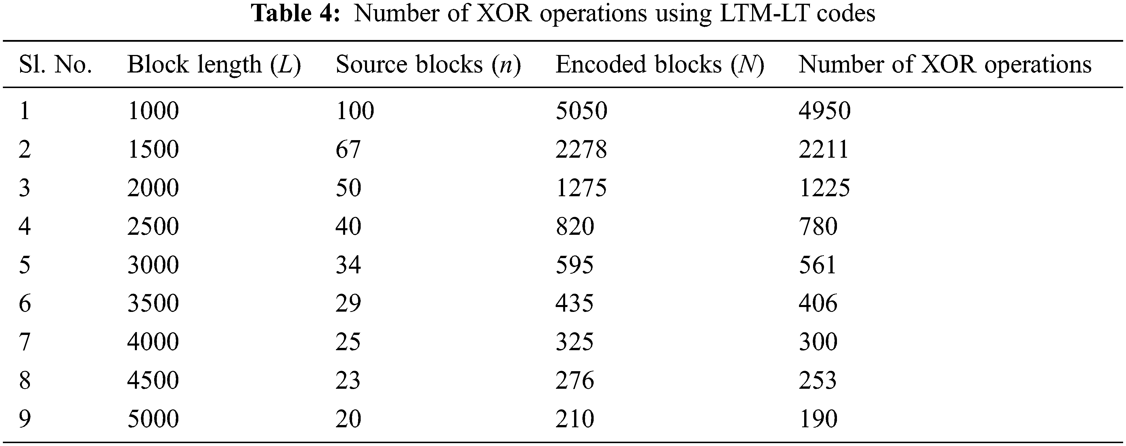
So, the SB4 (that is Source Block 4) is recovered. Similarly, the number of XOR operations performed in the decoder can also be decreased. Tab. 4 illustrates the number of XOR operations involved in LTM-LT codes. It is observed that by increasing the block length, we can very much reduce the number of XOR operations.
5.2 No Need of Transmitting the Neighbor Array
Since bandwidth is a scarce resource, any degree distribution algorithm should lead into no wastage of channel bandwidth. As per the proposed LTM based degree distribution, the same logic has been used for generating the Neighbor array with the help of unique block id in both the sender and receiver that are located in the different areas. It is a major advantage of LTM compared to the traditional algorithms as there is no need for transmitting the Neighbor array along with each and every encoded block or packet.
5.3 Zero Redundancy at Zero Percentage Erasure
Consider that the number of packets that got erased in the process of transmitting through the channel is zero. As per our proposed LTM based degree distribution, by the first n (where n = no of source blocks) encoded blocks itself, it is possible for the decoder to recover all the source blocks. Hence, the redundancy is zero. But in RSD, the number of packets transmitted will be always more than n. Hence, in conventional LT codes, there exists redundancy.
5.4 Security of Data Being Transmitted
Since the data is being encoded and data transferred over the network, the attackers have no idea of the data being transmitted, their degree, as well the neighbor array combination used for generation of the data. So, it is almost impossible to crack the data which is being transmitted. Hence the data is secure.
6 Improving Distributed Storage System’s Performance by Using LTM-LT Codes
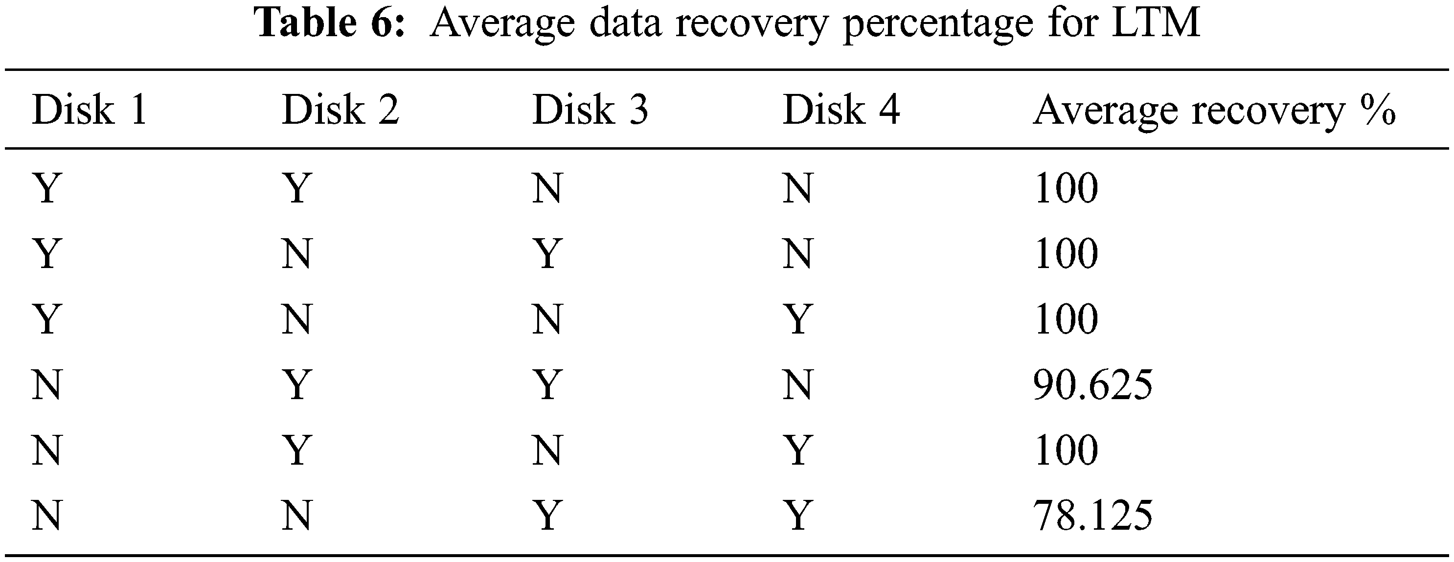
Tabs. 5 and 6 show the average recovery percentage of whole data when certain disks got failed (denoted as ‘N’, where ‘Y’ represents available) when implemented using RSD and LTM respectively. In this analysis, 4 disks are considered for distributed storage in both RSD and LTM.
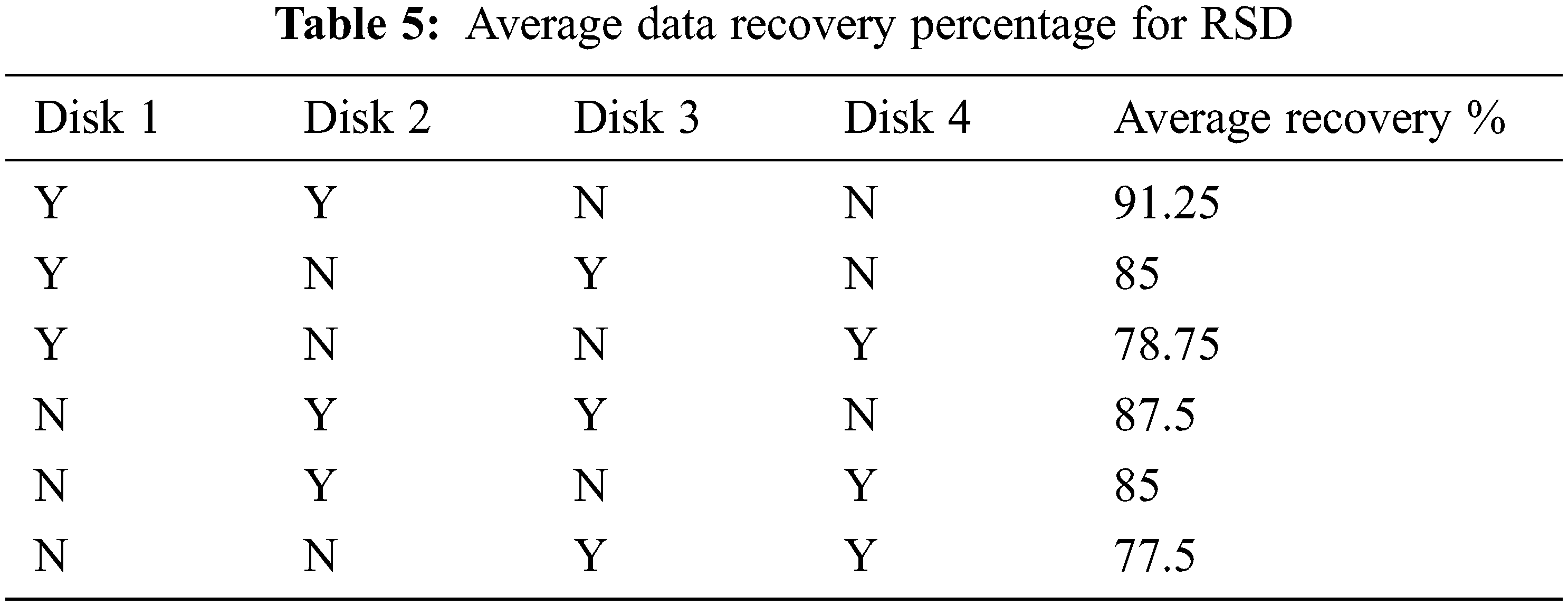
From Tab. 5, it is inferred that RSD falls short when utilized in a distributed storage system, particularly when many disks fail.
From Tab. 6, it is inferred that LTM performs well in most of the cases in distributed storage system. On comparing the results of both RSD and LTM, it is clearly shown that LTM performs better than RSD in case of multiple disk failures in distributed storage system. The performance of RSD and LTM has been plotted by varying the different combinations of 4 disks as shown in Fig. 16.
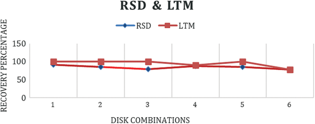
Figure 16: Performance of RSD and LTM by varying disk combinations
In this work, a novel degree distribution approach has been proposed for LT codes using LTM. The objective of LTM-LT codes is to achieve 100% decoding efficiency over erasure channels even at higher erasure probability. Simulation results clearly show that the proposed LTM-LT codes achieve better utilization of bandwidth, higher decoding efficiency at higher erasure probability, less encoder/decoder delays in comparison with traditional degree distribution schemes. In the conventional LT codes, the degree and the neighbor source blocks are sent to the decoder along with each encoded block. In LTM-LT codes, instead of sending all those encoding related data, a unique block id will be assigned to each encoded block by LTM encoder that is transmitted along with each encoded block. Since the logic used in encoder and decoder are same, the decoder can easily generate the degree and neighbor array for the corresponding received encoded block. When compared with the conventional LT codes, this results in the usage of very less bandwidth and found to be more reliable. Hence, these characteristics of LTM–LT codes can find its suitability in the distributed storage. Further analysis of LTM-LT codes for smaller message length is a part of our future work.
Funding Statement: The authors received no specific funding for this study.
Conflicts of Interest: The authors declare that they have no conflicts of interest to report regarding the present study.
1. J. W. Byers, M. Luby and M. Mitzenmacher, “A digital fountain retrospective,” ACM SIGCOMM Computer Communication Review, vol. 49, no. 5, pp. 82–85, 2019. [Google Scholar]
2. M. Luby, “LT codes,” in Proc. 43rd Annual IEEE Symposium on Foundations of Computer Science, Vancouver, BC, Canada, pp. 271–280, 2002. [Google Scholar]
3. A. Yazdanialahabadi and M. Ardakani, “A distributed low-complexity coding solution for large-scale distributed FFT,” IEEE Transactions on Communications, vol. 68, no. 11, pp. 6617–6628, 2020. [Google Scholar]
4. O. I. Khalaf and G. M. Abdulsahib, “Optimized dynamic storage of data (ODSD) in IoT based on blockchain for wireless sensor networks,” Peer-to-Peer Networking and Applications, vol. 14, pp. 2858–2873, 2021. [Google Scholar]
5. S. Wu, Q. Guan and S. Li, “A novel LT scheme without feedback messages for IoT of smart city scenarios,” Wireless Communications and Mobile Computing, vol. 2021, pp. 1–8, 2021. [Google Scholar]
6. C. P. Kumar and R. Selvakumar, “Reliable and secure data communication in wireless sensor networks using optimal locally recoverable codes,” Peer-to-Peer Networking and Applications, vol. 13, pp. 742–751, 2020. [Google Scholar]
7. F. Belabed and R. Bouallegue, “Novel fountain data estimation scheme by exploiting Bayesian model classification in wireless sensor networks,” International Journal of Wireless and Mobile Computing, vol. 18, no. 2, pp. 183–193, 2020. [Google Scholar]
8. R. Gaeta and M. Grangetto, “On the robustness of three classes of rateless codes against pollution attacks in P2P networks,” Peer-to-Peer Networking and Applications, vol. 4, no. 6, pp. 1–10, 2021. [Google Scholar]
9. M. Shirvanimoghaddam, “Primitive rateless codes,” IEEE Transactions on Communications, vol. 5, no. 12, pp. 1–14, 2021. [Google Scholar]
10. X. Song, T. Lei, L. Cheng, N. Cheng and S. Ni, “A novel lt encoding algorithm with low error floor,” in Proc. 2021 6th Int. Conf. on Intelligent Computing and Signal Processing (ICSP), Xi’an, China, vol. 4, pp. 139–144, 2021. [Google Scholar]
11. X. Song, N. Cheng, Y. Liao, S. Ni and T. Lei, “Design and analysis of lt codes with a reverse coding framework,” IEEE Access, vol. 9, no. 4, pp. 116552–116563, 2021. [Google Scholar]
12. S. M. Mirrezaei, “Towards systematic Luby transform codes: Optimisation design over binary erasure channel,” Electronics Letters, vol. 56, no. 11, pp. 550–553, 2020. [Google Scholar]
13. L. Zhang and L. Su, “Goal-oriented design of optimal degree distribution for LT codes,” IET Communications, vol. 14, no. 16, pp. 2658–2665, 2020. [Google Scholar]
14. J. Shang, W. Xu, C. -H. Lee, X. Yuan and J. Lin, “REF Codes: Intermediate performance oriented fountain codes with feedback,” IEEE Transactions on Vehicular Technology, vol. 69, no. 11, pp. 13148–13164, 2020. [Google Scholar]
15. J. Dai, F. Zhang, W. Yang and K. Kang, “An efficient design of systematic rateless codes,” Wireless Communications and Mobile Computing, vol. 20, no. 2, pp. 1–8, 2020. [Google Scholar]
16. I. J. L. Paul, S. Radha and J. Raja, “Throughput and bit error rate analysis of Luby transform codes with low and medium nodal degree distributions,” American Journal of Applied Sciences, vol. 11, no. 9, pp. 1584–1593, 2014. [Google Scholar]
17. I. J. L. Paul, S. Radha and J. Raja, “Performance analysis of joint degree distribution (JDD) in luby transform codes,” Journal of Computer Science, vol. 11, no. 1, pp. 166–177, 2015. [Google Scholar]
18. N. I. Abdulkhaleq, I. J. Hasan and N. A. J. Salih, “Mitigation of packet erasure using new fountain code design,” in Proc. 2018 IEEE Int. Multidisciplinary Conf. on Engineering Technology (IMCET), Beirut, Lebanon, pp. 1–7, 2018. [Google Scholar]
19. N. M. El-Gohary, F. E. Abd El-Samie and M. M. Fouad, “Study the performance of fountain codes in wireless communication systems,” International Journal of Computer Science and Information Security, vol. 12, no. 10, pp. 12–25, 2014. [Google Scholar]
20. H. Sehat and P. Pahlevani, “An analytical model for rank distribution in sparse network coding,” IEEE Communications Letters, vol. 23, no. 4, pp. 556–559, 2019. [Google Scholar]
21. S. Chanayai and A. Apavatjrut, “Fountain codes and their applications: Comparison and implementation for wireless applications,” Wireless Personal Communications, vol. 5, no. 12, pp. 1–16, 2021. [Google Scholar]
22. S. S. Emara, S. Fong, B. Li, A. Khisti, W. -T. Tan and J. Apostolopoulos, “Low-latency network-adaptive error control for interactive streaming,” IEEE Transactions on Multimedia, vol. 6, no. 13, pp. 1–16, 2021. [Google Scholar]
23. M. Cui, H. Zhang, Y. Huang, Z. Xu and Q. Zhao, “A Fountain-coding based cooperative jamming strategy for secure service migration in edge computing,” Wireless Networks, vol. 7, no. 12, pp. 1–14, 2021. [Google Scholar]
24. A. Zhou, B. Yi, Y. Liu and L. Luo, “An optimal tree-structured repair scheme of multiple failure nodes for distributed storage systems,” IEEE Access, vol. 9, pp. 21843–21858, 2021. [Google Scholar]
25. T. Okpotse and S. Yousefi, “Systematic fountain codes for massive storage using the truncated poisson distribution,” IEEE Transactions on Communications, vol. 67, no. 2, pp. 943–954, 2019. [Google Scholar]
26. X. Ye, J. Li, W. -T. Chen and F. Tang, “LT codes based distributed coding for efficient distributed storage in wireless sensor networks,” in Proc. IFIP Networking Conf. (IFIP Networking), Toulouse, France, vol. 7, pp. 1–9, 2015. [Google Scholar]
27. H. Kang and O. Jeeyun, “Beyond user control and two-way communication: The four-factor model of interactivity of wrist-worn smart devices,” Media Psychology, vol. 7, no. 3, pp. 321–332, 2021. [Google Scholar]
28. J. Chen, S. Zheng, Q. Hu and Y. Kuo, “A frame-level encoder rate control scheme for transform domain Wyner-Ziv video coding,” Multimedia Tools and Applications, vol. 76, pp. 20567–20585, 2017. [Google Scholar]
29. A. Tiwari and V. Lalitha, “Secure raptor encoder and decoder for low storage blockchain,” in Proc. Int. Conf. on COMmunication Systems & NETworkS (COMSNETS), Bangalore, India, vol. 6, pp. 161–165, 2021. [Google Scholar]
30. X. He and K. Cai, “On decoding fountain codes with erroneous received symbols,” in Proc. IEEE Information Theory Workshop (ITW), Riva del Garda, Italy, vol. 4, pp. 1–5, 2021. [Google Scholar]
31. H. Nie, X. Jiang, W. Tang, S. Zhang and W. Dou, “Data security over wireless transmission for enterprise multimedia security with fountain codes,” Multimedia Tools and Applications, vol. 79, pp. 10781–10803, 2020. [Google Scholar]
32. S. Xu and D. Xu, “Design of degree distributions for finite length LT codes,” Wireless Personal Communications, vol. 98, pp. 2251–2260, 2018. [Google Scholar]
33. A. Mallick, M. Chaudhari and G. Joshi, “Fast and efficient distributed matrix-vector multiplication using rateless fountain codes,” in Proc. ICASSP 2019–2019 IEEE Int. Conf. on Acoustics, Speech and Signal Processing (ICASSP), Brighton, UK, vol. 15, pp. 8192–8196, 2019. [Google Scholar]
34. L. Al-Awami and H. H. Hassanein, “Energy efficient distributed storage systems with lt-codes in resource-limited wireless systems,” in Proc. 2015 IEEE Global Communications Conf. (GLOBECOM), San Diego, CA, USA, vol. 15, pp. 1–6, 2015. [Google Scholar]
 | This work is licensed under a Creative Commons Attribution 4.0 International License, which permits unrestricted use, distribution, and reproduction in any medium, provided the original work is properly cited. |