DOI:10.32604/iasc.2022.025410
| Intelligent Automation & Soft Computing DOI:10.32604/iasc.2022.025410 | |
| Article |
Motor Torque Measurement Using Dual-Function Radar Polarized Signals of Flux
1Department of Electronics and Instrumentation Engineering, Easwari Engineering College, Chennai, 600089, India
2Department of Electrical and Electronics Engineering, GKM College of Engineering and Technology, Chennai, 600063, India
3Department of Electrical and Electronics Engineering, Saveetha Engineering College, Chennai, 602105, India
4Department of Computer Science and Engineering, Aalim Muhammed Salegh College of Engineering, Chennai, 600055, India
*Corresponding Author: B. Chinthamani. Email: bchinthamani74@gmail.com
Received: 22 November 2021; Accepted: 06 January 2022
Abstract: Motor Torque (MT) measurement plays a vital role for evaluating the performance of squirrel cage induction motor during operating conditions. Accurate and continuous measurements of MT provide information regarding driving load capacity, performance degradation of motor, reduces downtime and increases the efficiency. Traditional inline torque sensors-based measurement becomes inaccurate during abrupt change in load during starting condition of motor due to torque spikes. Mounting of torque sensor on motor is a major problem during torque measurement. Improper mounting of sensor acquires signals from other inefficient driveline components such as gearbox, couplings, and bearing. In this paper, we propose a non-contact method for MT measurement using dual-function ultra-wide band radar sensor and called as motor torque- design for reliability (MT-DFR) method, which measures torque through and air gap magnetic flux. Torque is orthogonal to air gap flux density. Air gap flux varies with motor speed, different load, and supply voltage. Dual-function ultra-wide band radar sensor signal reflect from Air gap flux and polarized. Polarized signals of Dual-function ultra-wide band radar process with multi-synchro squeezing transform (MSST) and obtain Instantaneous Frequency (IF) of air gap magnetic flux. MSST provides better representation of reconstructed signal with higher concentration for oscillatory electromagnetic waves. MT measured from IF of MSST and Gaussian process regression. Proposed method of MT measurement performs in different loading conditions such as such as no load, static and transient load conditions, and induced torque spikes. The proposed MT-DFR method predicts the torque with 98.10% accuracy compared to traditional method and ground truth verified.
Keywords: Induction motor; ultra-wide band radar; polarization; multi-synchro squeezing transform; instantaneous frequency; gaussian process regression; torque prediction
Induction motor is used in different industrial applications such as milling, drilling and automation operations such as lifting, grinding and pulling. Induction motor performance degrades over period of time due to continuous operation and poor quality of power supply. Induction motor performance and efficiency evaluates through MT. MT is the force acting on rotor of motor for rotation in axis. Rotor angular acceleration increases with force. Rotor in induction motor rotates due to magnetic field. The magnetic field generates from stator windings. The magnetic flux from stator winding radially flows through air-gap of winding and rotates rotor. The magnitude and density of radial flux from stator winding cause torque in the motor. The radial flux interacts with rotor axial current and produces torque in motor. The torque produced in the motor is in similar direction of rotating magnetic field. MT depends on slip size in motor. MT is maximum, when rotor resistance is equal to rotor inductive reactance. The motor torque measure with different types of transducers such as inline and rotary torque sensors. The sensor measures motor torque from rotating shaft through optical reflectance, inductive, current signatures. The rotary torque sensor measures tightening torque of motor, placed in line with motor shaft. Hall effect transducer consists of ferromagnetic material in ring form, and mounted near the shaft. Torque from motor shaft exerts magnetic pressure on ring. Hollow cylindrical conductor magnetic field of ring in motor varies due to torque of motor. The magnetic field from ring sense with hall-effect transducer for torque estimation. [1] Stress sensitive amorphous ribbons made of Fe-Si-B and attached to shaft. The amorphous ribbons anisotropies vary by 45 degrees due to anisotropy position of ribbons. The torque of shaft influences permeability of amorphous ribbons. The phase sensitive rectifier and sensing coil estimates motor torque from difference in amorphous ribbon permeability [2]. A field sensor of permanent magnetization placed in circumferential opposite direction of shaft. The torque exerted on motor shaft increases magnetic field near the polarized band and varies permanent magnetisation. The permanent magnetisation field strength and polarity from field sensor is used for torque estimation [3]. The surface acoustic wave (SAW) torque transducer consists of thin metal electrodes and piezoelectric substrate. The metal electrodes are in different stiffness level. The electrodes resonate at different frequencies when excited by radio frequency source. The resonating frequency varies depending on distance between electrodes in torque transducer. Torque applied to transducer cause tension and compression. The torque influences resonant frequency of electrodes. The resonant frequency varies proportional to torque. The motor torque estimate with sum and frequency difference of transducer signal [4]. The torque ripples in motor measure with reaction torque sensor. The torque estimate with strain gauge sensor. Strain gauge sensor displace with respect to torque ripple [5]. The magnetic flux density of motor shaft varies with respect to deformation in shaft. The magnets attach to either side of shaft with 45-degree angle. Hall-effect sensor produces electrical signal proportional to magnetic flux density [6]. The position sensor measures torque in steady state and transient speed conditions. The air gap torque estimate from flux and current of loaded motor [7]. A silicon cantilever improves the sensitivity of strain gauge. Strain gauges fabricated with polysilicon resistor and silicon dioxide improves torque measurement. The resistors form wheat stone bridge is sensitive to axial force [8]. The torque of motor estimate with torque meters.
Inference from literature survey
The torque measurement using various sensors such as acoustic, mems-vibration, strain gauge, in line sensors never provides the accurate results due to contact type sensors and mounting the sensors over motor at different locations. Moreover, repeatability of the existing methods in different types of motor and motor duty cycle such as continuous duty, intermittent periodic duties, short-time duty and continuous operation with intermittent load show different torque measurement results. So a unique method to measure torque is required and for different size and duty motors inaccuracy in existing sensor is due to contact type. A novel non-contact method needs to be developed. The below problems statement explain the drawback of existing contact methods of torque measurements with their limitations.
The traditional dynamometer has higher response time to applied torque, and less accurate compared to contact torque sensor [9]. The in-line torque sensor estimates torque with error due to brush noise, bearing noise and different motor speeds. [10]. The reaction torque sensor has reduced dynamic response time, never measure true torque in shaft and measure reaction torque. Shaft–slip ring-style torque sensor torque measurement accuracy is less due to electrical brush noise, brush maintenance and errors, bearing maintenance, revelations per minutes (RPM) limitations, Stiffness, Backlash or key imbalance [11]. The circular shaft–rotary transformer based torque measurement needs mathematical calculations, less accuracy and more uncertainty [12]. Analog telemetry torque sensor has low accuracy in torque measurement due to susceptible of metal objects located near by the motor and high inertia. Digital telemetry torque sensor accuracy in torque measurement is influenced by more data conversions. In-line, direct, clamp-on torque measurement using various sensors such as optical, strain gauge, acoustic, current, voltage, and power meter-based torque measurement never addressed torque spikes during motor torque measurement [13]. The existing sensors never measure accurate torque in small diameter shaft. Moreover, temperature of motor reduces accuracy of torque measurement. Repeatability of MT measurements is a challenging task [14]. Torque measurement is affected by axial, lateral, bending movement in shaft, linearity, hysteresis, environment and sensor output and sensitivity. Moreover, environmental factors influence the optical and acoustic sensor-based torque measurements. Furthermore, torque measurement using excitation coil and detection coil consume energy from radiating flux. The above sensors never measure static torque and dynamic torque of induction motor.
In this paper, novel non-contact method to measure torque with dual-function ultra-wide band radar (UWB) radar sensor polarized signal is proposed. Moreover, the air gap magnetic flux radiation through motor ventilator is directly proportional to motor torque. In this paper, motor torque predicts from radiated air gap magnetic flux with dual-function UWB radar sensor. The electromagnetic waves from dual-function UWB radar reflect by air gap magnetic flux emitted from motor are polarized. The flux from motor leads to resonance response and heavy polarity change in reflected electromagnetic wave of Dual-function UWB radar sensor signal. From polarized dual-function UWB radar sensor, signal IF is obtained through MSST algorithm. The motor torque predicts with IF and toque meter values by gaussian process regression.
i) To develop, motor torque measurement from air gap flux usingual-function UWB radar sensor and the proposed MT-DFR method measures dynamic and static torque using the reflected polarized signals of dual-function UWB radar sensor. The MT-DFR is a non-contact method suits for different size of motor.
ii) To analyse, torque spikes in Induction motor through the frequent change in heavy, low load, induced transient in motor and their corresponding instantaneous frequency is analysed with MSST algorithms.
iii) To analyse, efficient side lobes of dual-function UWB radar sensor polarised signals, which are reflected from air gap flux at varying load conditions through accurate prediction of Motor torque using Gaussian process regression. The motor torque measurement using MT-DFR method values are compared with the traditional method of torque measurement using strain gauge.
Motor Torque estimate from air gap flux through HB-100 doppler radar. The dual radar focus magnetic flux produced from stator, which rotates the rotor due to rotating magnetic field. The rotors axial current and stators magnetic field rotates the motor at high speed. The magnetic field from stator windings rotates rotor based on flux density from stator, stator and rotor surface radiates the flux through motor air gap. The magnetic flux from stator radially crosses the air gap. The rotor rotates to match speed of magnetic flux generated from stator. The magnetic field radially radiate through the motor ventilator. The magnetic flux in air gap is proportional to the applied voltage and frequency of Induction motor. The current in rotor bar interacts with magnetic flux of stator. The direction of torque is similar to rotating magnetic field. The flux produced in motor due to applied voltage and frequency represent by Eq. (1).
where,
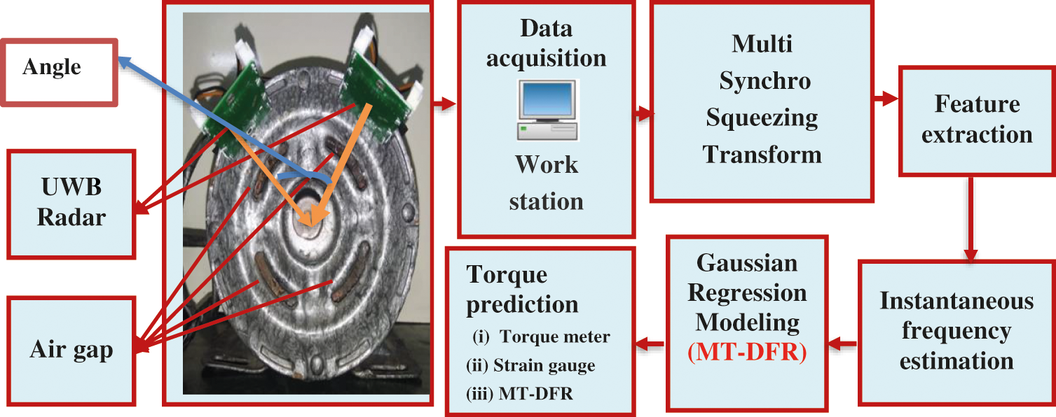
Figure 1: Overview of torque estimation through UWB radar multi-static propagation
The Flow diagram of motor torque estimation with MSST from spectral characteristic of electromagnetic wave is shown in Fig. 1. UWB radar place at 2 cm away from air gap of motor as shown in Fig. 2. The radar place at different location for multi-channel torque estimation. The UWB radar place parallel to each other and eliminate electromagnetic noise interference caused due to scattering effect.
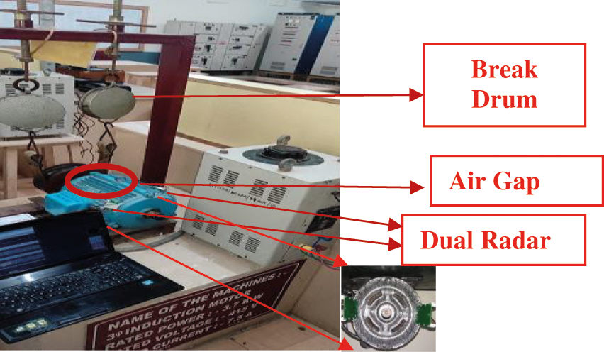
Figure 2: Dual function UWB radar mounted for obtaining polarised signal from air gap flux
The dual radar flux reflected signals acquired through the universal serial bus (USB) data acquisition card. The USB data acquisition model no model di-1100 is used for acquiring UWB radar signal and device consists of 4-r ±10 V differential analog inputs with 12-bit resolution. The device as high sample rates per channel such as 40 /30/24/20 kHz and 2 dedicated digital inputs. Analog inputs protect up to ±100 V and digital inputs protect up to ±30 volts direct current (VDC) or peak. Device has full scale range of about: ±10 V with full scale fixed input impedance of about 1 MΩ and never requires Isolation Furthermore, absolute accuracy is about 25°C, excluding common mode error ±12.5 mV at 25°C, Absolute maximum input without damage is about ±75 V at peak, continuous is about ±100 V peak. The device noise range is about 7.8 mV rms. The Maximum common mode voltage is about ±10 V and common mode rejection ratio is about 40 dB (dc - 60 Hz) and channel-to-channel crosstalk rejection: of about –80 dB. The device is enclosured with Hardened Plastic and can be mounted on Desktop or bulkhead. The device dimensions is about 2.625D × 5.5W × 1.53H in. (6.67D × 13.97W × 3.89H cm.)
UWB radar is of in X-band continues wave model No: HB100. Radar is X-band bi-static doppler transceiver, which has built-in dielectric resonator oscillator (DRO) and a pair of micro strip patch antenna array. Radar consumes current of 30 mA and supply voltage is between 4.75 V and 5.25 V. The Dimension of UWB radar is 10 × 5 × 1.5 cm; and weight of the radar is about 100 grams. The UWB radar is a monostatic device with transmitter and receiver placed in a single device. The radar emits electromagnetic waves in the range of 9.35 to 24.124 GHz. The UWB radar is an active transducer, which sense motor flux through signal polarity of echo signal. The spectral characteristic of electromagnetic (EM) waves changes depending on flux medium. The reflected waves from medium undergo wave polarization. The polarization of reflected wave is proportional to energy level of wave from flux medium.
The polarization (Ep) of reflected wave from air gap magnetic flux as medium represent by Eq. (2).
where, ‘V’ is the flux velocity, ‘Ft’ is the transmitted wave frequency, ‘C’ is the speed of light.
The
2.3 UWB Wave Polarization Due to Air Gap Magnetic Medium Reflection
UWB sensor EM reflected from air gap magnetic flux produced by stator receives by respective radar. The reflected microwave from flux undergoes variation in flux phase angle and leads to polarised signal components. The incident wave on flux represents by Eq. (3). The electromagnetic (EM) wave reflected from flux produced by stator receives by respective radar. The reflected microwaves from flux have s and p polarized signal components. The reflected microwave from flux undergoes variation in flux phase angle of polarised signal components. The incident wave on flux represent by Eq. (3).
where, ‘A’ represents amplitude vector of signal, ‘i’ is the imaginary unit, ‘k’ is the wave vector, ‘p’ represents position vector, ‘
Fig. 3 shows reflection of UWB radar electromagnetic waves from motor flux. The propagation of EM through the medium such as air and flux characterise by the relative permittivity of different medium. The relative permeability of air represent by 1. Since, the relative permeability is constant the permeability for air and flux equals to 1. The incidence wave on flux represents by θ and the wave reflected from flux has an angle ‘θ’. The ‘s’ polarised electromagnetic (EM) wave reflect by flux completely and ‘p’ polarised wave becomes partially polarized.
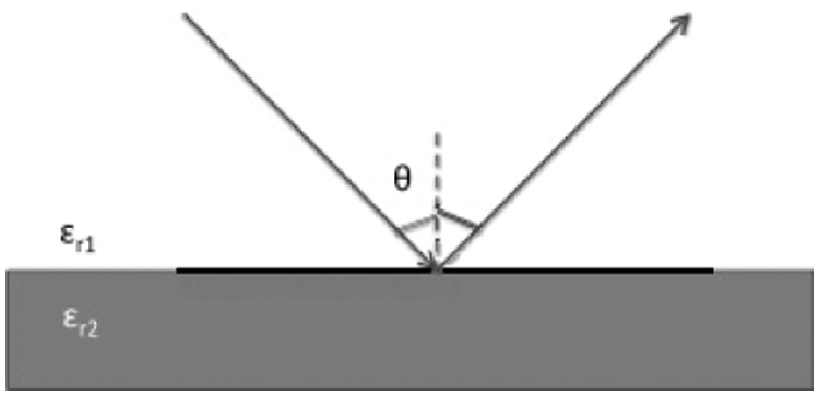
Figure 3: Electromagnetic wave reflection
The velocity of wave emitted from UWB radar represent by Eq. (5).
where, ‘
The polarization of incident electromagnetic wave changes with respect to dielectric air gap magnetic flux from motor, the reflecting signal has s and p polarization in wave with magnitude and phase angle variation. The spectral variation of wave depends on dielectric constant of reflecting flux medium. The reflected wave from flux medium represent by R in Eq. (7). The Fig. 4 shows the polarization and magnitude wave changes because of reflecting flux medium. The magnitude and polarization of ‘s’ and ‘p’ wave increases with respect to flux density radiated from air gap of motor.
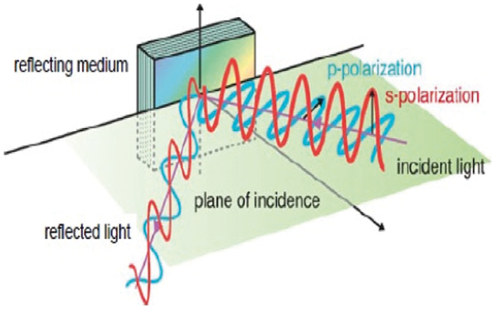
Figure 4: s and p wave polarization variation due to reflective medium
The incident EM wave upon incidence undergoes wave widening and referred as transmittance. The incident beam width widens. The transmittance (T) of the wave is represented as in Eq. (8).
2.4 Dual Function Radar and Torque Measurement
Dual-function radar system shares single hardware and spectral resources for acquiring polarized radio frequency reflected from air gap flux from motor. Dual-function radar system provides waveform parameter information more efficiently with similar radar aperture and frequency bandwidth. However, orthogonal waves for measuring MT from air gap flux from motor with similar spectral pattern is never realizable using single radar. To solve the above problem, dual radar need to be mounted in motor for coherent processing interval (CPI). dual radar received beam pattern of each radar changes is beam pattern, amplitude, phase depending on the air gap flux from motor and measure motor torque (MT) after analyzing with MSST.
2.5 Multi Static Propagation of Signal
Multi static system consists of more than one radar spaced apart from each other to locate flux produced in air gap between rotor and stator. The electromagnetic wave from the UWB transmitters monitors emitted heavy magnetic flux from stator and rotor air gap magnetic flux. The UWB radars detect air gap flux by positioning radar above air gap region of motor. The multiple bi static receivers of radar receive scattered electromagnetic wave from flux of motor. The reflected wave from air flux have time difference in arrival and‘s’, ‘p’ wave polarization. The flux produce ellipse for UWB radar with transmitter and receiver pair. The echoed waves from air flux of radars correlate for torque estimation. The transmitted UWB wave from radar represent by Eq. (9).
where, Pt – Power of transmitted wave, Pr – Power of received wave, Gt – Power gain of transmitting antenna, Gr – Power gain of receiving antenna,
R – Distance between radar and air flux emitted through motor ventilator. The EM from UWB radar reflects from air flux with Brewster angle. The polarising angles of reflected EM wave signal vary with air flux emitted from motor. The wave, angle of reflection and permittivity changes analyse with MSST algorithm for IF estimation. The instantaneous phase estimate with MSST parameters such as mean, variance, entropy, kurtosis. The induction motor with specification such as 3 horsepower, 24 slots. 8 poles and 0.99 winding factor is used for this study.
2.6 Multi Synchro Squeezing Transforms (MSST)
MSST developed through by consecutive synchro squeezing transform (SST) operation with short time fourier transform (STFT) as mother wavelet. MSST improves time frequency resolution of reflected phase polarised wave from air gap magnetic flux. The reflected oscillatory signal from air flux represents by Eq. (10).
where, A (t) represents instantaneous amplitude of polarize wave,
where
The instantaneous frequency of reflected polarized UWB dual radar wave due to air flux from motor represent by Eq. (13).
The linear change in reflects polarized UWB Radar wave is due to higher flux leakage from motor represent by Eq. (14).
Hence, the IF estimate of signal with synchro squeezing transform (SST) operation represents by Eq. (15).
The iterative operation of SST – MSST estimates instantaneous frequency (IF) for fast varying polarity of reflected wave from air gap reflected polarized flux. The first SST operation calculates time frequency response (TFR) of wave represent by Eq. (16). The SST operation repeated on (TFR) with STFT and calculates IF of wave represent as in Eq. (17). The SST operation terminates, when time frequency coefficients never change and satisfied condition represent as in Eq. (18).
Torque of motor estimate from polarised wave with phase angle variation of UWB dual radar electromagnetic wave acquired from Data acquisition system and process with MATLAB. The polarize electromagnetic wave was analysed with MSST algorithm and determine instantaneous frequency from polarised dual radar signal. The motor torque is analysed for different load conditions and evaluate torque estimation accuracy. The torque is measured with conventional torque meter and correlated with UWB dual radar predicted torque measurement. The torque measurement was conducted on test bed with 1 KW induction motor. The different loads are mechanically coupled to the shaft of induction motor IM. The IM electrical parameters such as speed, output power and torque are measured. UWB radar is placed above the motor ventilator and measure air magnetic flux radiated from stator air gap. UWB radar signal has acquired and saved in computer through data acquisition (DAQ) and MATLAB signal acquisition tool box. For the torque measurement, experiments were conducted for different load conditions such as no load, dynamic load, static load condition tests and external transient conditions. The load test is conducted on motor running at synchronous speed of 1200 rpm. The load is coupled mechanically to shaft of motor. The load on brake drum adjusted for different kilogram with mechanical adjustments. The UWB radar signal is acquired for different load conditions. The signals acquired thrice for each load condition and improved the reliability. The SST algorithm decomposes the UWB radar signal up to five levels and concentrates on time frequency representation of signal. The Fig. 5 shows electromagnetic wave decomposed with MSST algorithm for no load condition. The MSST algorithm determines rapidly changing signal polarity through IF and estimates the concentrated signal as shown in Fig. 6. The torque estimate from motor during dynamic load condition through analysing the reflected electromagnetic wave parameters. Fig. 7 shows the MSST decomposition of EM wave at dynamic load. The flux from motor varies with respect to supply voltage. The transient voltage leads to weak flux density emitted at the motor ventilators. The weak flux density causes weak echo of microwave signal from UWB radar. The weak electromagnetic signal has minimal periodic variation. The MSST reconstructs the periodic variation of signal by reassignment operation. The single SST operation never provides accurate instantaneous frequency for estimation of the instantaneous coefficients of periodic varying signal reflected and polarizing signal from dual radar.
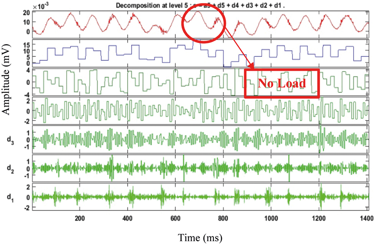
Figure 5: MSST decomposition of EM wave at no load
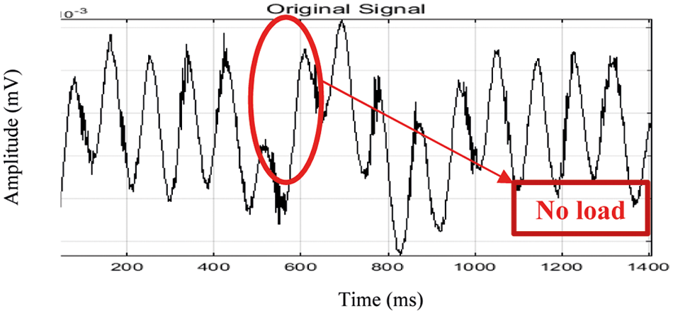
Figure 6: Concentrated time frequency representation of EM wave at No load condition
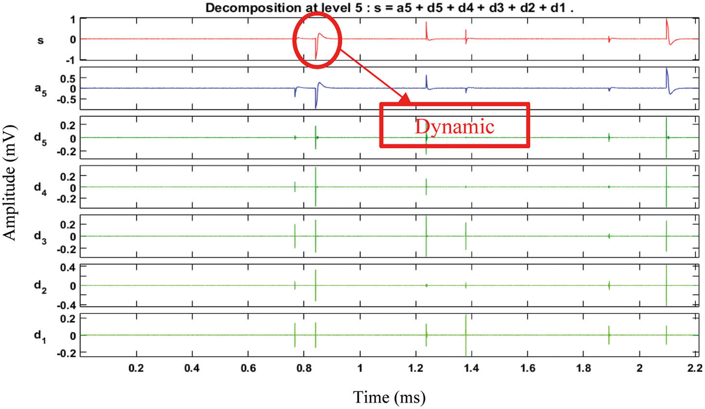
Figure 7: MSST decomposition of EM wave at dynamic load
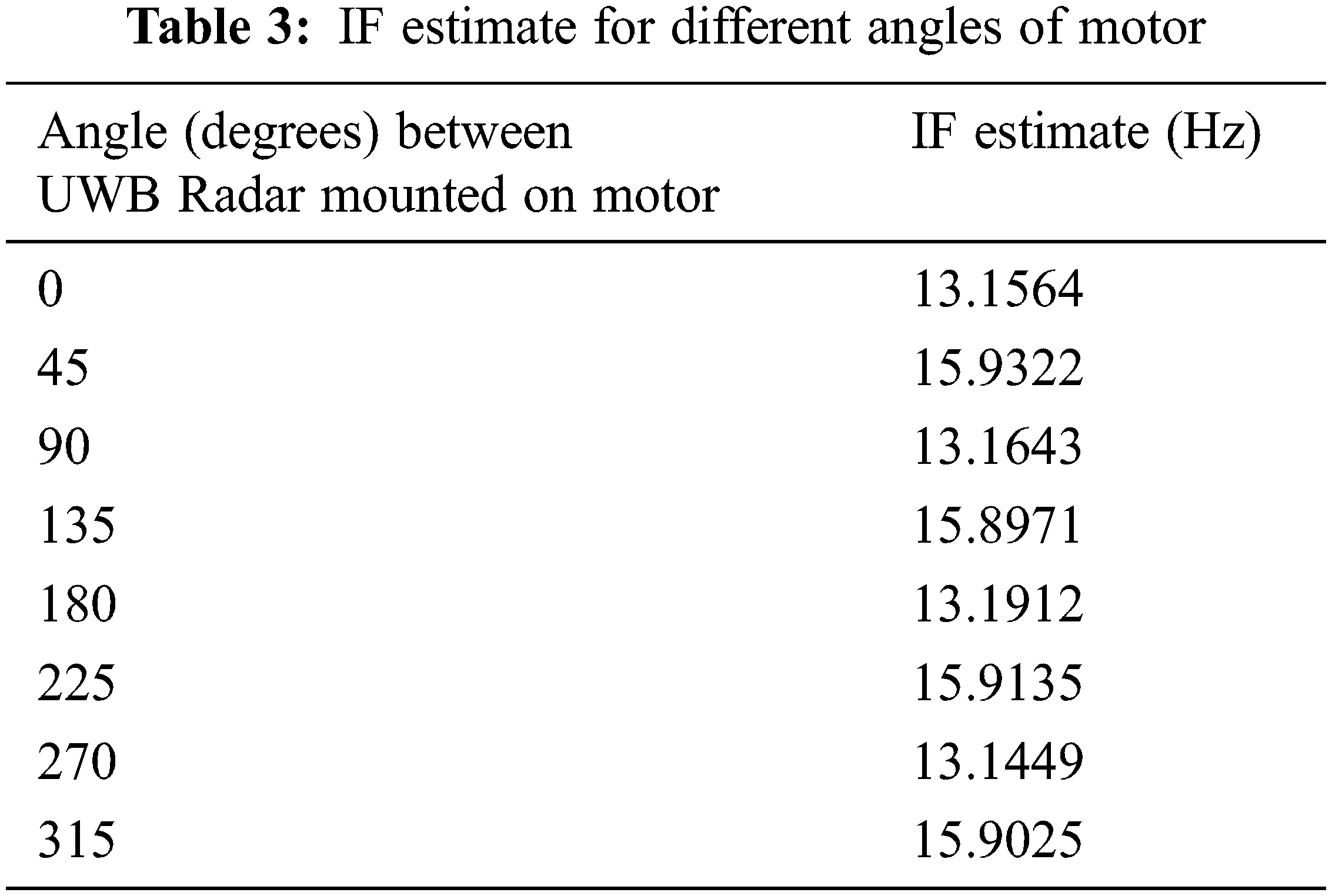
Multiple SST operation reconstructs the reflected polarised signal with ideal time frequency coefficients. MSST produces minimal IF from signals of air gap of stator. The MSST decomposes the input signal and estimate the IF coefficients. The decomposed signal at level three provides accurate and estimate is shown in Fig. 8. Similarly, motor torque tested under static load condition. The load 1.5 kg was coupled to brake drum. The applied load leads to more air gap flux and high IF is produced. The flux emission cause higher periodic variation of UWB radar signal. The IF estimate of signal is high as in d3 and shown in Fig. 9. From the reconstructed signal IF is estimated and shown in Fig. 10. Furthermore, Tab. 1 shows the signal parameters of reconstructed signal during different load conditions. The torque was estimated for different input voltages as shown in Tab. 2. The input voltages to IM vary with variac. The variation in input voltage leads to proportional to flux generation and torque characteristics of IM. The decrease in input voltage leads to minimal flux radiated from air gap. The reflected EM wave is acquired with UWB and has minimal magnitude, periodic variation due to weak echo signal from radiated flux. The IF is used to estimation of induction motor (IM) torque of IM operating at 210 voltage, compared to IM operating at 190 volts. The IF estimate reduced with respect to low supply voltage. The IF estimate is reduced due to low magnitude and periodic variation of ‘s’ and ‘p’ polarised UWB dual radar EM wave reflected from flux radiated through air gap. The wave polarization is reached maximum, when the motor torque was high and increase in supply voltage and causes the IF estimation reduction. The IF estimates reduced with increasing speed due to slip. The IF estimate of motor for different input voltage and shown in Tab. 3.
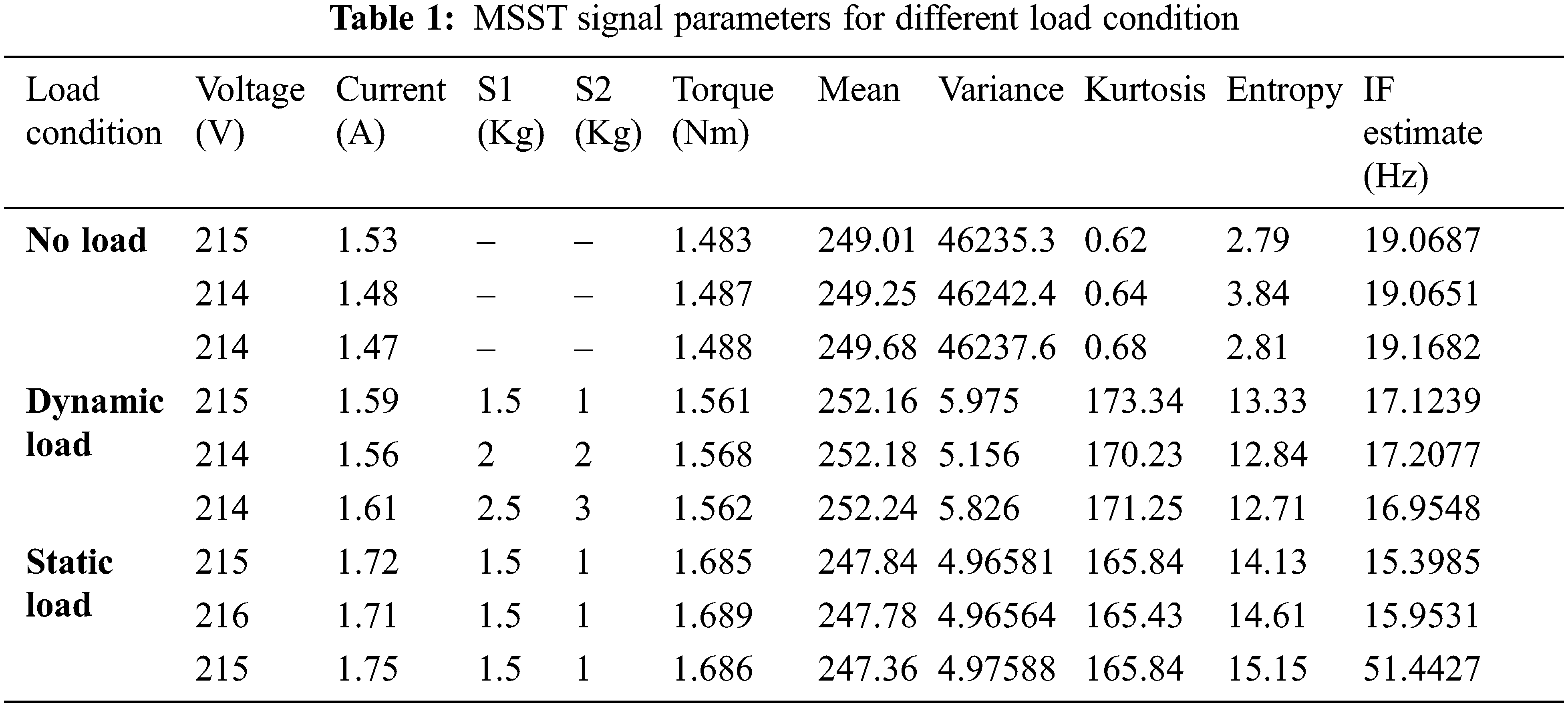
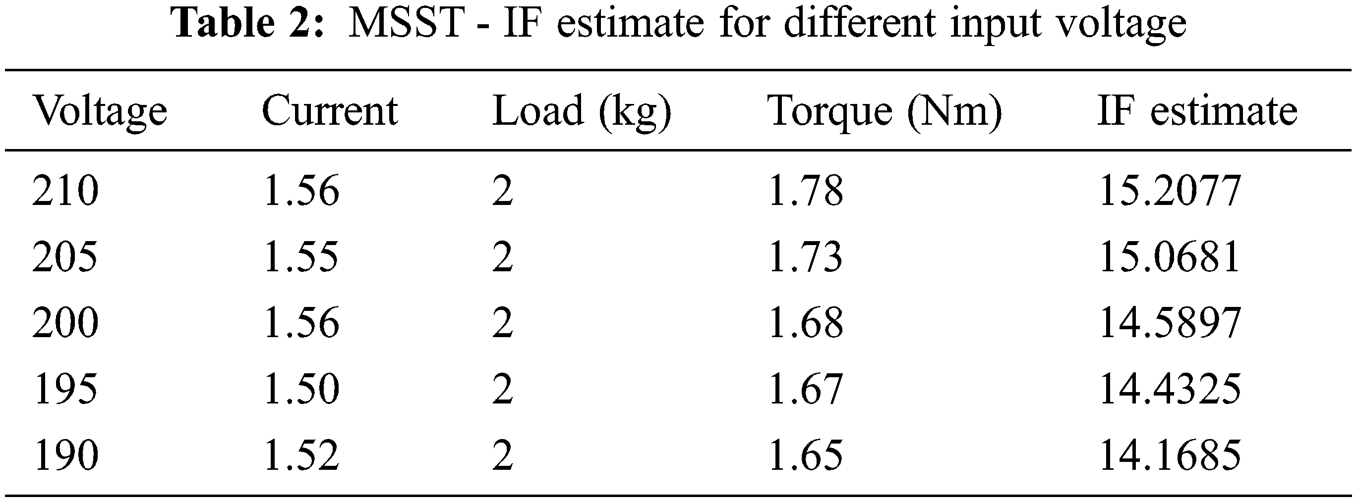
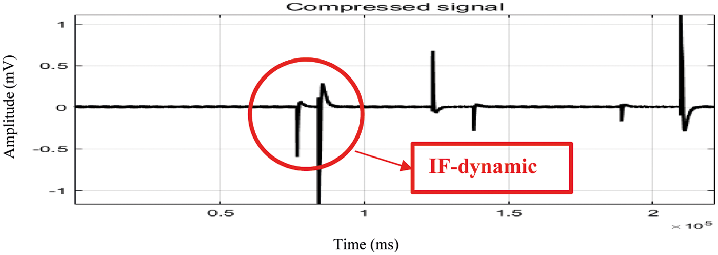
Figure 8: Concentrated time frequency representation of EM wave at dynamic load condition
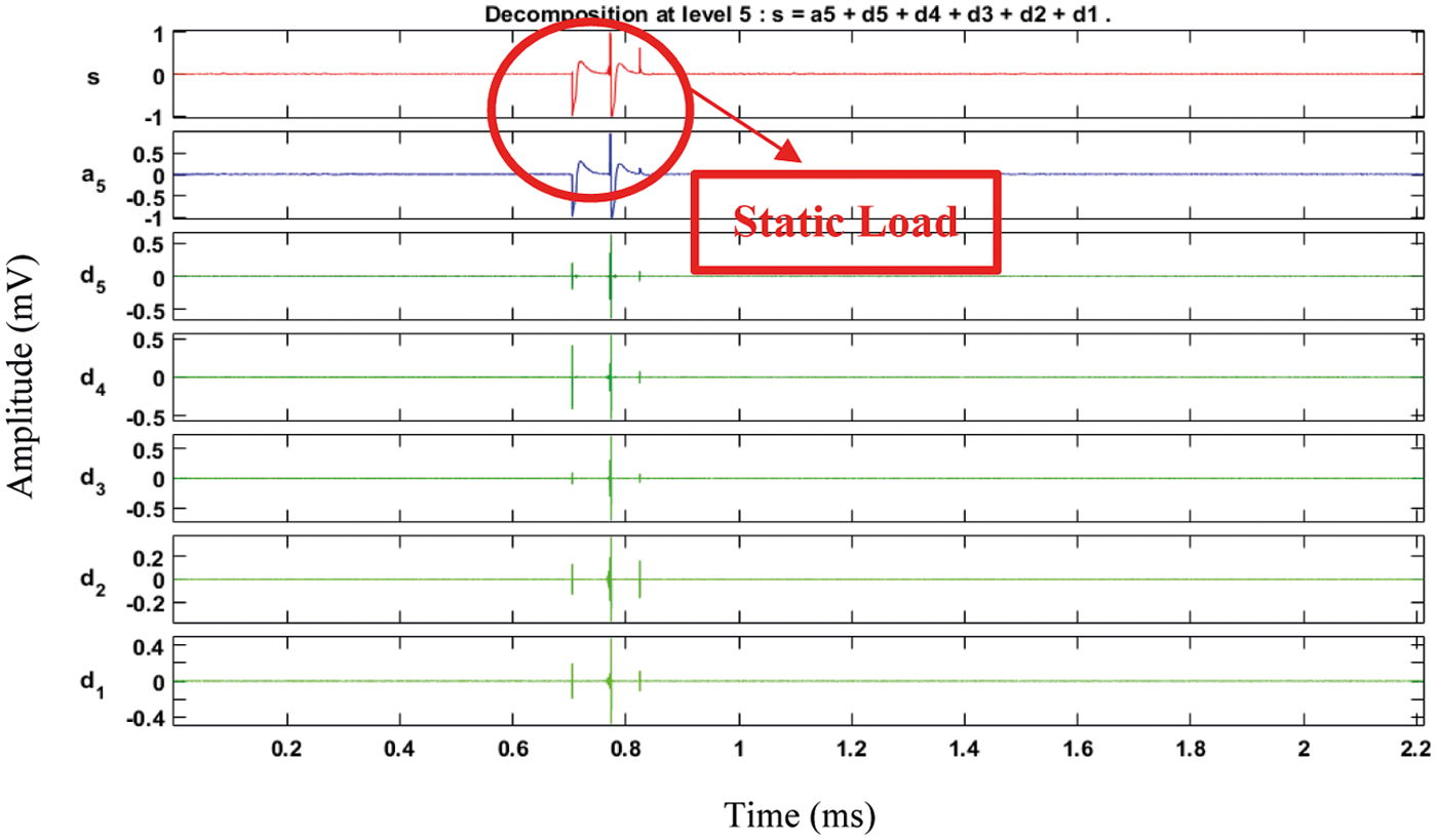
Figure 9: MSST decomposition of EM wave at static load
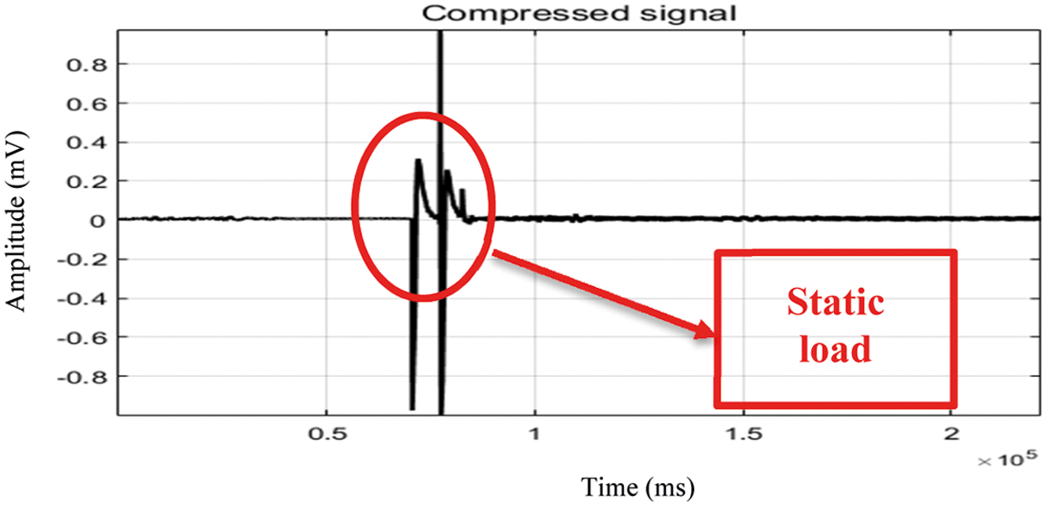
Figure 10: Concentrated time frequency representation of EM wave at static load condition
3.1 Mounting of UWB Radar in Different Angles
Optimal location for mounting UWB is identified through reflection signals from UWB dual radar sensor fixed at different locations for accurate motor torque (MT) measurement. The UWB radar was placed at 0, 45, 90, 135, 180, 225, 270, 315, and 360 degrees. The MSST analysis of acquired signal shows the IF estimate increased with respect to input voltage for 45, 135, 225 and 360 degrees. The foresaid angle provides maximum electromagnetic wave reflection from flux with negligible losses. The magnitude and periodic variation of reflected EM electromagnetic (EM) wave undergoes losses due to low flux strength emanating at 0, 90, 180, 270 degrees. The flux strength from air gap reduces due to motor enclosure. The decomposition of echoed electromagnetic wave at 0, 180 degree is shown in Fig. 11. From the analysis 0 and 180 degree are found to be the optimum location for accurate measurement of torque.
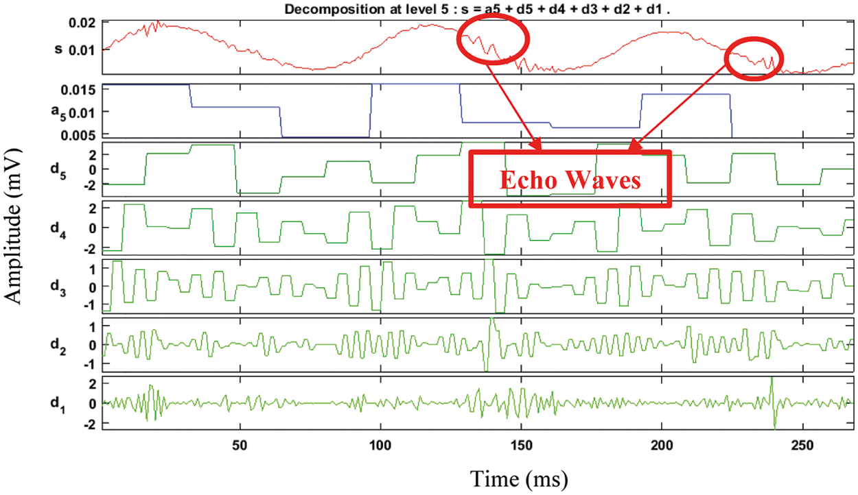
Figure 11: MSST decomposition of electromagnetic wave echoed from 180 degree angle of UWB radar signal
UWB dual radar signal undergo minimal polarization however; the magnitude of echoed wave is similar to transmitted wave. The Tab. 3 shows the IF estimate of flux from motor at different angles for 220 input voltage. The motor was mechanically coupled to load with 2 kg running at 1100 rpm.
3.2 Prediction of MT Using Gaussian Regression
Gaussian process regression modelling use non-parametric bayesian approach and provide relationship function between unknown variables. The gaussian process optimizes the function of independent variables, kernels of gaussian function and provides assumption, relation among variables. The gaussian process distributions map the inputs to dependent variable. In gaussian distribution, the input x and output y are related as in Eq. (19).
Mathematically, the input and output variables relate by function f. The function provides relation for different input variables. The gaussian process provides accurate prediction for new values based on observations made from different input and outputs. For exploring the process, gaussian regression selects the input and output variables to model the function. The gaussian process gains knowledge through learning the relationship between input and output variables. Furthermore, the exploration – exploitation function optimizes the samples of uncertain in input values, produces high outputs. The exploration refers to the uncertainty sample inputs and exploitation refers to error values produced due to current values in gaussian knowledge. The exploration and exploitation phase use model and acquire knowledge of function ‘f‘ and select appropriate method for input based on function knowledge. The weights distribute among variables with uncertain samples by defining distribution function. The gaussian process provides accurate prediction for selection of input and output variables, which predict values, that satisfies multivariate gaussian distribution. The output ‘N’ of a corresponding function with input ‘a’ is represented as in Eq. (20).
where, ϵ is the noise term. The noise represents the quantitatively spaced random values of variables. The noise term follows specific distribution and shows the functions uncertainty. The uncertainties of the distribution minimize by evaluating the output of function with respect to different inputs. The gaussian process of function distributed with respect to observations and represented as in Eq. (21).
where, m(x) represents the mean function. The gaussian process spread over a function represent by mean and covariance function k (x, x’). The covariance function represents the value change due to different input point x and x’. The kernel of the gaussian function represents by k. The radial basis function kernel minimizes the possibility of similar predicted values for observations, which are widely spaced from each other. The radial basis function is represented as in Eq. (22).
where,
3.3 Ground Truth Verification of Proposed MT Measurement
Tab. 4 shows Ground truth verification of proposed motor torque- ddesign for reliability (MT-DFR) based motor torque (MT) measurement with accuracy percentage. The proposed MT-DFR obtain an accuracy of 98.106% for an average from 25 new motors tested with different load conditions. The motor torque estimated with Gaussian process regression is evaluated with new set of motors. The Internet of things (IoT) implement with MAT LAB things speak tool box. The things peak [15] provides real time private and public data monitoring through internet. The predicted torque values send as data packets from MAT LAB through internet to things peak cloud. The torque values plot in real time with time stamps as shown in Fig. 12. The process takes negligibly minimal time and suitable for real time torque monitoring. The torque values from IoT are used for analysing performance evaluation and improve efficiency.
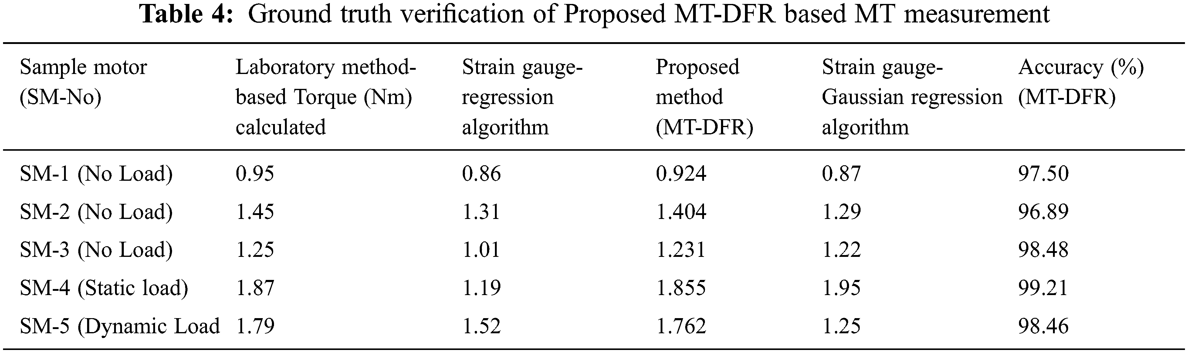
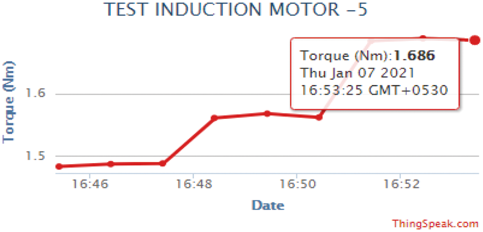
Figure 12: Real time torque monitoring by IoT
This paper discussed about induction motor torque prediction from reflected UWB radar through MT-DFR method. The torque measure from magnitude and phase of polarized electromagnetic wave from air gap magnetic flux. The polarized electromagnetic wave process with multi-synchro squeezing transform (MSST) algorithm for estimation of IF. The MSST decomposes the electromagnetic wave up to five levels. The IF from MSST algorithm estimate MT. The Induction motor torque estimate in different loaded conditions, such as no load, static load and transient load. The MSST IF estimation showed inverse relation with respect to torque of motor. The IF estimate showed precise measurement of torque during high speed and lowering speed of motor. The time frequency resolution of UWB characteristic signal is used for IF estimation and varies torque for different speed and load of motor. The torque estimates from IF estimates through gaussian process regression. The predicted torque from induction motor through UWB radar has negligible error percentage compared to torque measured with torque meter. The proposed MT-DFT method predicted MT values using gaussian regression method compared with strain gauge sensor measured torque values. The strain gauge sensor frequency based motor torque is predicted with regression modelling and gaussian modelling. From comparison, MT-DFT performs better and provides 96% of accuracy, when compared with strain gauge-regression and strain guage-gussian methods. From the comparison, gaussian prediction algorithm performs better and dual function radar sensor performs better for different size of motors and duty motors such as continuous duty, intermittent periodic duties, short-time duty and continuous operation with intermittent load. The proposed MT-DFR method can be used for condition monitoring of Induction motor in industries. MT measurement in induction motor at different ambient temperature in electrical vehicles can be extended for further studies.
Funding Statement: The authors received no specific funding for this study.
Conflicts of Interest: The authors declare that they have no conflicts of interest to report regarding the present study.
1. I. J. Garshelis, “A torque transducer utilizing a circularly polarized ring,” IEEE Transactions on Magnetics, vol. 28, no. 5, pp. 2202–2204, 1992. [Google Scholar]
2. K. Harada, I. Sasada, T. Kawajiri and M. Inoue, “A new torque transducer using stress sensitive amorphous ribbons,” IEEE Transactions on Magnetics, vol. 18, no. 6, pp. 1767–1769, 1982. [Google Scholar]
3. I. J. Garshelis and J. M. Cuseo, “Negative hysteresis in magnetoelastic torque transducers,” IEEE Transactions on Magnetics, vol. 45, no. 10, pp. 4471–4474, 2009. [Google Scholar]
4. T. M. O’Sullivan, C. M. Bingham and N. Schofield, “High-performance control of dual-inertia servo-drive systems using low-cost integrated saw torque transducers,” IEEE Transactions on Industrial Electronics, vol. 53, no. 4, pp. 1226–1237, 2006. [Google Scholar]
5. G. Heins, M. Thiele and T. Brown, “Accurate torque ripple measurement for pmsm,” IEEE Transactions on Instrumentation and Measurement, vol. 60, no. 12, pp. 3868–3874, 2011. [Google Scholar]
6. J. C. S. Borges, D. B. B. de Deus, A. C. Lima Filho and F. A. Belo, “New contactless torque sensor based on the hall effect,” IEEE Sensors Journal, vol. 17, no. 16, pp. 5060–5067, 2017. [Google Scholar]
7. H. M. Flieh, E. Totoki and R. D. Lorenz, “Dynamic shaft torque observer structure enabling accurate dynamometer transient loss measurements,” IEEE Transactions on Industry Applications, vol. 54, no. 6, pp. 6121–6132, 2018. [Google Scholar]
8. N. Svedin, E. Stemme and G. Stemme, “A static turbine flow meter with a micromachined silicon torque sensor,” Journal of Microelectromechanical Systems, vol. 12, no. 6, pp. 937–946, 2003. [Google Scholar]
9. F. Tinazzi and M. Zigliotto, “Torque estimation in high-efficencyipm synchronous motor drives,” IEEE Transactions on Energy Conversion, vol. 30, no. 3, pp. 983–990, 2015. [Google Scholar]
10. S. Hwang, M. Lim and J. Hong, “Hysteresis torque estimation method based on iron-loss analysis for permanent magnet synchronous motor,” IEEE Transactions on Magnetics, vol. 52, no. 7, pp. 1–4, 2016. [Google Scholar]
11. Y. Zhou, D. Zhang, X. Chen and Q. Lin, “Sensorless direct torque control for saliency permanent magnet brushless DC motors,” IEEE Transactions on Energy Conversion, vol. 31, no. 2, pp. 446–454, 2016. [Google Scholar]
12. M. N. Uddin and M. M. Rahman, “Online torque-flux estimation-based nonlinear torque and flux control scheme of IPMSM drive for reduced torque ripples,” IEEE Transactions on Power Electronics, vol. 34, no. 1, pp. 636–645, 2019. [Google Scholar]
13. D. Reigosa, Y. G. Kang, M. Martínez, D. Fernández, J. M. Guerrero et al., “SPMSMs sensorless torque estimation using high frequency signal injection,” IEEE Transactions on Industry Applications, vol. 56, no. 3, pp. 2700–2708, 2020. [Google Scholar]
14. M. Martinez, D. Reigosa, D. Fernández, J. M. Guerrero and F. Briz, “Enhancement of permanent-magnet synchronous machines torque estimation using pulsating high-frequency current injection,” IEEE Transactions on Industry Applications, vol. 56, no. 1, pp. 358–366, 2020. [Google Scholar]
15. ThingSpeak, https://thingspeak.com/. [Google Scholar]
 | This work is licensed under a Creative Commons Attribution 4.0 International License, which permits unrestricted use, distribution, and reproduction in any medium, provided the original work is properly cited. |