DOI:10.32604/iasc.2022.023035
| Intelligent Automation & Soft Computing DOI:10.32604/iasc.2022.023035 | |
| Article |
A Novel Controller for Microgrid Interactive Hybrid Renewable Power Sources
Government College of Engineering, Tirunelveli, 627007, Tamilnadu, India
*Corresponding Author: P. Kavitha. Email: kavitha.paulsamy6@gmail.com
Received: 26 August 2021; Accepted: 05 January 2022
Abstract: In this paper, a self-sufficient electric power generation is proposed by using hybrid renewable sources like solar and wind turbines to favor a smart and green environment. This distributed generation unit is connected to the grid through an 3Φ inverter. The power drawn from the hybrid unit is stored in the batteries to transfer power during the non-availability of power sources. This standalone power conversion and storage system are developed by using power electronic converters and controllers to ensure balanced power flow operation. A PI (Proportional Integral) controller is utilized for generating the PWM (Pulse Width Modulation) pulses for the wind side converter. The GWO (Grey Wolf Optimization) optimized PI controller is used to control the PV (Photovoltaics) side SEPIC (Single-Ended Primary-Inductor Converter) for improvising the transient response of the system. The generated power is interfaced with grid through a three phase inverter, which is controlled by dq (Direct-axis and Quadrature-axis) theory. The power quality problems are effectively eliminated with the proposed converters. Thus, a continuous stable power is fed into the grid through the proposed approach. An automatic control is enabled for easy operation. The system is modeled in MATLAB and a prototype is developed to verify the simulation results.
Keywords: PV and Wind power system; SEPIC converter; GWO-PI controller; microgrid
The current is one of the essential inventions of science and so it is not possible to think the world without electricity. However, many places in the globe still have no reliable and quality power. The total required gross power of India in the period of 2018–2019 is 1,181 kWh per capita. Though most of the remote areas are declared as electrified, the total demand is not completely met, which leads to more power supply issues. Due to unplanned and planned outages, various electricity demands are left unsatisfied. The natural and man-made reasons like overloading, snapping and short circuiting have caused unexpected disruptions. Even in the power availability, it is found that the voltage is reduced and unbalanced. A routine power cuts are also performed by companies for the economic interest.
Industrialization is one of the important factors in developing the energy security. The distributed generations utilize the locally available renewable sources (wind, solar, biomass, and small hydro) to achieve self-reliability in independent power generation. It encourages the pollution free power generation and diminishes the issues of conventional fossil fuels. The shortage of fossil fuels and the emission of harmful gases have urged the world to find out the alternative of fossil fuels. The design optimization and the electro mechanical components are the big challenges in attaining the expected output power. The renewable energies provide better substitutability than the traditional power sources. Several renewable sources are fused together to construct an intelligent grid structure and to provide continuous electricity without any interruption.
Different initiatives are taken to enhance the self-sufficient renewable power system. These initiatives have paved the way for the implementation of renewable power system, which has the ability of giving self-sufficient power by integrating more renewable sources [1]. The PV and wind are the commonly employed hybrid renewable power sources [2]. In India, wind energy comprises 10% and solar energy comprises more than 30% of total electricity.
A wind-PV system is clearly discussed in the literature. The combined renewable sources face substantial challenges by the expansion of power industries. The control methods in the integration of wind and PV are ceaselessly enhanced with robust units, which paves the way for the future green energy based power establishments. Nowadays, the integration of wind-PV and the grid is increasing in an exponential manner. The controlling strategy is used by the power producers to maintain the rigidity and stability of the grid [3]. The combined Wind-PV system is employed to enhance the energy capture ability by working at optimum power through various MPPT (Maximum Power Point Tracking) schemes. The utilization of power electronic components is optimized with the hybridization of PV-wind configuration. The DFIG (Doubly fed Induction Generator) based wind farms are suitable for widely varying wind speed turbine system.
Various control techniques are available for attaining efficient power flow in hybrid power system. The modeling of system design has relied on the kind of conversion system and converters. It requires more concern on the technical issues, which are has evoked various researches [4–7]. A hardware setup of hybrid distributed renewable power system has been developed for small scale and laboratory scale generation unit [8,9]. A grid connected PV-wind setup has been addressed in [10–12] and standalone hybrid system is discussed in [13–16]. An autonomous operation improves the performance of the distributed centers by controlling the microgrid resources with the assistance of artificial intelligence control system. A smart system is established by managing and controlling the energy for regulating the flow of power in the grid. The intermittent nature of renewable system makes the conventional PI controller unsuitable for many applications. Hence, an optimized PI controller is used to vary the controller parameter [17].
The chief objective of this research is to model and develop a laboratory size hybrid renewable system, which uses power of wind, PV and an energy storage system. The power from two separate sources is supervised by the control methods, which are used in the practical controlling situations. The proposed system is utilized to undergo a real time research in the renewable energy field. It has an open architectural setup, in which several power electronic converters and controlling methods are adopted to analyse the performance of microgrid. In consideration with the favorable advantages of the hybrid wind-PV generation system, a novel effective topology is suggested in this study to integrate the PV-wind with the grid and energy storage device. The subsequent sections of this study are listed below. 1. The grid associated PV-wind system with separate VSCs (Voltage Source Converter) and energy storage system is used to feed sustainable power to the grid. 2. Independent closed loop operations are employed in this systems to control the PWM rectifier [18–21] and the SEPIC converter. 3. A state-space archetype is modelled for the wind-PV generation system to analyse the stability of overall system. 4. The effectiveness of the proposed microgrid generation system is investigated in simulation under various operating conditions in time-domain and the outcomes are assessed with the laboratory prototype.
In this hybrid microgrid scheme, the PV-DFIG based wind generator combination acts as a primary energy source whereas the battery backup acts as a secondary source. The SEPIC converter and 3ϕ IGBT (Insulated-Gate Bipolar Transistor) based PWM rectifier are used in the power conversion stage to track optimum power from the solar and wind. A buck-boost converter, which has bidirectional power flow capacity connects the battery setup with the PCC (Point of Common Coupling) to reduce the intermittent property of renewable source and to provide local support to the grid during the non-availability of renewable source.
A flexible and cost effective interfacing is realized by transmitting all the power with the aid of an energy efficient dc transmission system. The DC output of the converter is maintained as 600 V, which is then fed to the grid through a 3Φ inverter. The overall cost is reduced and power conversion is improved by increasing the utilization of converters to the maximum extend. Thus, the proposed system shown in Fig. 1 has a good scope of integration of renewable sources with grid. The output of the PV side SEPIC converter is given to PI controller and compared with reference dc potential of 600 V. The error is given to the comparator, in which a 10 kHz triangle carrier wave is utilized to produce the command pulses for the SEPIC converter. The tuning of variables for PI controller is done by GWO approach. The stator of the DFIG, which is connected with wind turbines gives 3ϕ supply from grid. Moreover, the rotor is connected with 3ϕ PWM rectifier. When rotor speed is higher than the synchronous velocity, the wind energy is transformed into equivalent AC electrical power. In simulation, the speed of wind is set to vary from 4 to 16 m/s. The rectifier is utilized for converting the generated AC voltage into dc. This voltage is analogized with Vref to generate the error. This error is given to the comparator for producing the required pulses to the rectifier.
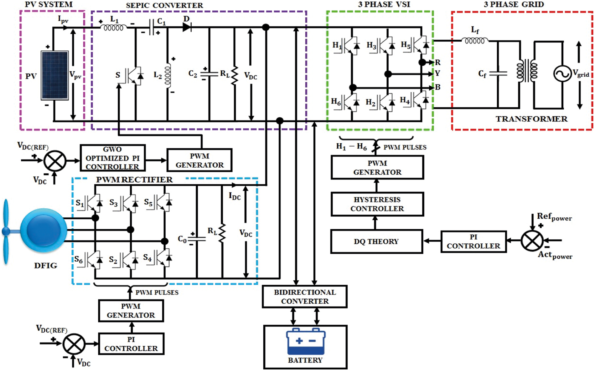
Figure 1: Overall circuit diagram of proposed system
The output of PV and wind is stored in batteries as a backup power source. The batteries are integrated with the PCC through the bidirectional buck-boost converter. The power flow direction is controlled through RNN (Recurrent Neural Network) based controller by managing the charging and discharging modes of batteries. The reference voltage of batteries is set 10% below the dc-link potential. In this case, 540 V is set as reference battery voltage. If the voltage across battery is same as reference voltage, the duty ratio of the pulses for the converter is maintained at 0.5 by the RNN controller. Thus, the converter blocks the flow of power in both directions. When the battery voltage becomes greater than 540 V, the converter functions in boost mode (duty ratio > 0.5) and the power starts flowing from the battery to the inverter. As the battery voltage drops below 540 V, the RNN controller changes the operating mode of the converter into buck mode (duty ratio <0.5) to charge the battery. The RNN is implemented to manage the SOC (State of Charge) of battery by using the reference voltage of the battery. It is adaptable for any specific reference voltage and it protects the battery from overcharging.
Then the dc potential is transformed into AC by with the assistance of a 3ϕ inverter and the output of the inverter is injected to grid. The grid synchronization is achieved with the assistance of dq theory. By using the voltage and current sensors, the actual power at the grid is estimated and analogized with reference 1 kW power. The error output of the comparator is given to dq theory, which converts the 3ϕ power component into 2ϕ direct and quadrature components. The 2ϕ component is consisted of active and reactive parts of the total power. From the calculation, the direct component, which indicates the active current component is derived. This current is analogized with the grid current, where the output of the comparator indicates the reactive component in the grid. The hysteresis controller, which is placed at the output of the comparator produces the required PWM pulse for the inverter.
2.1 Modeling of the Proposed System
The solar PV based generation is regarded as the significant system of renewable energy source as it provides several benefits like, zero fuel requirements, pollution free nature, less maintenance and less noise. The equation, which relates the voltage–current of PV panel is mentioned as,
where, the voltage and current of PV is represented as VPV and IPV. The series resistance is indicated as RS; the charge of electron is denoted as q; the short circuit is denoted as ISC; the reverse saturation current is represented as Io. The amount of cells, which are linked in series and parallel are indicated as ns and np. The PV output power is given as,
SEPIC converter has the ability of operating in both buck and boost mode by following the optimum power from the PV system. The circuit of the SEPIC converter is provided in Fig. 2. The wind power control system is provided in Fig. 3. The Figs. 4 and 5 represents the RNN based control of power and Control of 3 Phase VSI using dq theory.
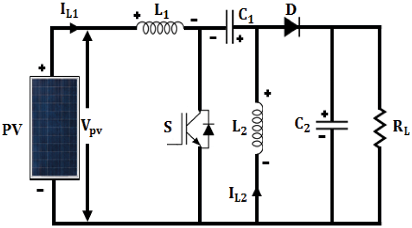
Figure 2: PV fed SEPIC converter
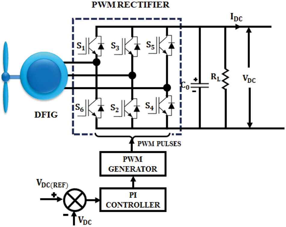
Figure 3: Wind power control system
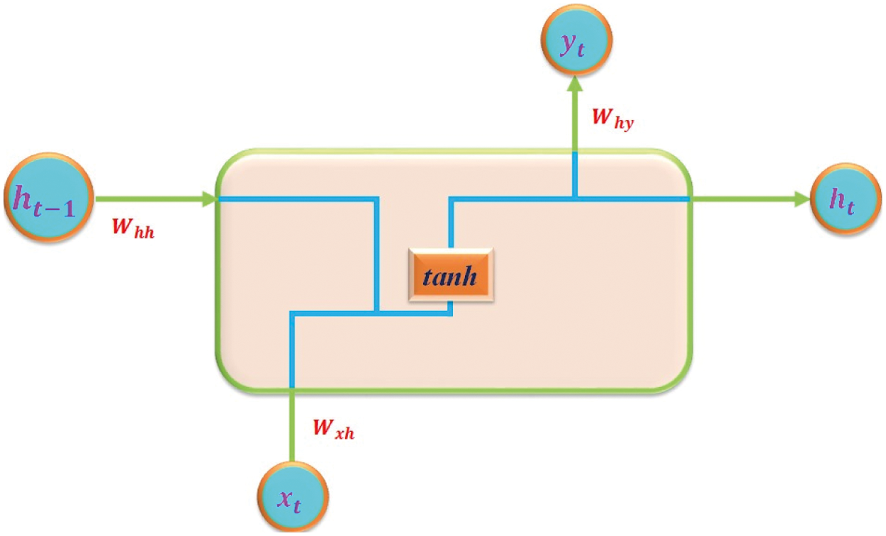
Figure 4: RNN based control of converter
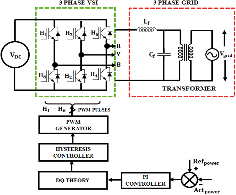
Figure 5: Control of 3ϕ VSI using dq theory
Based on the switch positions (Sc), the differential equations are written as,
The state space modeling of the SEPIC converter is expressed as
The meta-heuristic GWO algorithm imitates the grey wolves social manners. The wolves stay in a group of 5–12 members. In this gathering, the dominant wolf is specified as alpha (α), the following members are recognised as beta (β), which help α in taking decision. The remaining individuals of the gathering are categorised as δ and ω.
The order of prey chasing by the grey wolves is: searching for the prey, encompassing the prey, chasing, and assaulting the prey.
xi denotes the location of wolves; xp denotes the location of food; D denotes distance; A & C denotes vectors
where r1 and r2 represent the arbitrary numbers among [0, 1].
The variable is gradually reducing from 2 to 0 as the iteration is repeated. In order to search the position of prey, the search individuals for |A| > 1 are split. The procedure of obtaining the food is accomplished by converging the search individuals for |A| < 1. The attack is directed by α with the support of β and δ. In several conditions, the GWO algorithm stuck at local minimum, but the variables A and C aids the optimization to prevent the stagnation.
The wind power system includes a turbines, a DFIG, AC-DC rectifier and PI controller. The electrical power output from the wind is written as,
where, ρ signifies density of air (kg/m3); A signifies the region surrounded by rotor blades (m2); v signifies the wind velocity (m/s) and Cp is a power parameter, which is depending on tip velocity ratio and angle of pitch.
The utilization of wind turbine with variable velocity is discussed in [14–16]. The output of DFIG has high dependence over the velocity of wind, which is rectified with the assistance of a 3ϕ IGBT PWM rectifier [16].
The PI variables like Kp and Ki are tuned to lessen the error voltage e(t).
The output of u(t) controller is represented as,
The Integral Absolute Error (IAE) is chosen as the control objective by GWO algorithm for minimalizing the error-integrating function. The mathematical expression of IAE is defined as,
where ‘t’-time; e(t)-error between Vref and VDC of Modified Luo converter. The Kp and Ki values of PI controller are automatically tuned by GWO algorithm on the basis of the Objective function. With the fine-tuned values of Kp and Ki using GWO optimization approach, the reference signal is generated by PI controller, which is then analogised with high frequency carrier signal to create pulses for SEPIC converter.
The batteries require a bidirectional power converter to keep the dc-link potential at the optimum voltage of 600 V at the grid, which is typically greater than the maximum voltage level of battery (540 V). The reason of using a low battery voltage is to increase the life-time and to improve the reliability of the battery. It aids in eliminating the problems like cell voltage equalization in high power models. When the dc voltage of the renewable sources is lower than the terminal voltage of battery, the bidirectional converter works in a step up mode to extract the energy from batteries to the PCC. When the dc-link potential is more than the battery terminal potential difference, the converter changes to buck mode and so the power flows from the PCC to charge the batteries. The PWM pulses of the converter are controlled by RNN.
Initially, the duty ratio is kept as 0.5 and the converter neither operate in boost nor buck mode. Hence there is no power flow across batteries. According to the difference between the magnitude of dc-link potential and Battery terminal reference voltage, the duty cycle of the converter is varied by the RNN controller.
2.6 3ϕ Inverter Control Using DQ Theory
The grid synchronization is achieved by considering the phases of grid voltage and inverter output voltage. Among several methods of grid synchronization, grid voltage filtering is used in dq and αβ reference frames. Initially, the 3ϕ abc is transformed into 2ϕ αβ stationary reference frame and then to dq reference frame, which revolves at synchronous velocity. Various control methods are available to control the 3ϕPWM VSI (voltage Source Inverter), which is connected with grid for controlling the active and reactive powers. A well-known small signal model is used, in which a 3ϕ system is converted into dq frame (rotating reference). This process is specified as Park's transformation.
The 3ϕ PWM controller provides 3ϕ PWM signals by using three channels. The Clarke transformation is employed in 3ϕ system to reduce three-phase components into 2ϕ stationary reference frame components. The latter two components play a primary role in generating the PWM pulses.
The below equation represents the Park transformation where the stationary frame is converted into rotating frame
Thus Clarke transformation converts (3ϕ–2ϕ) stationary reference frame and Park transformation converts 2ϕ stationary frame to rotating frame.
A time scale simulation setup of the PV-wind system is developed in Matlab to evaluate and validate the system performance. A 1 KW is chosen as the ratings of the power source. The entire model is constructed by employing the sim power-system toolbox. The discrete type simulation is used with a sampling time of 20 ms. The aim of this scheme is to provide consistent power to the grid under several generating situations using hybrid sources. The solar insolation is controlled by varying the temperature and hence it provides various irradiance levels from 800 W/m2 (170 V) to 1000 W/m2 (200 V). The wind velocity is controlled by changing the velocity of the fan blower from 4 to 12 m/s. Around 15 numbers of 12 V batteries are serially connected to get an output voltage of 180 V. With the initial short circuit current of 10 A the panel arrays maintain an average of 2.5 A over the simulation time. The voltage at the converter output and battery terminal of the given input conditions are shown in Figs. 6 and 7. Though, the changes in the solar insolation and wind velocity are only step variations, the changing environment conditions make it practically impossible.
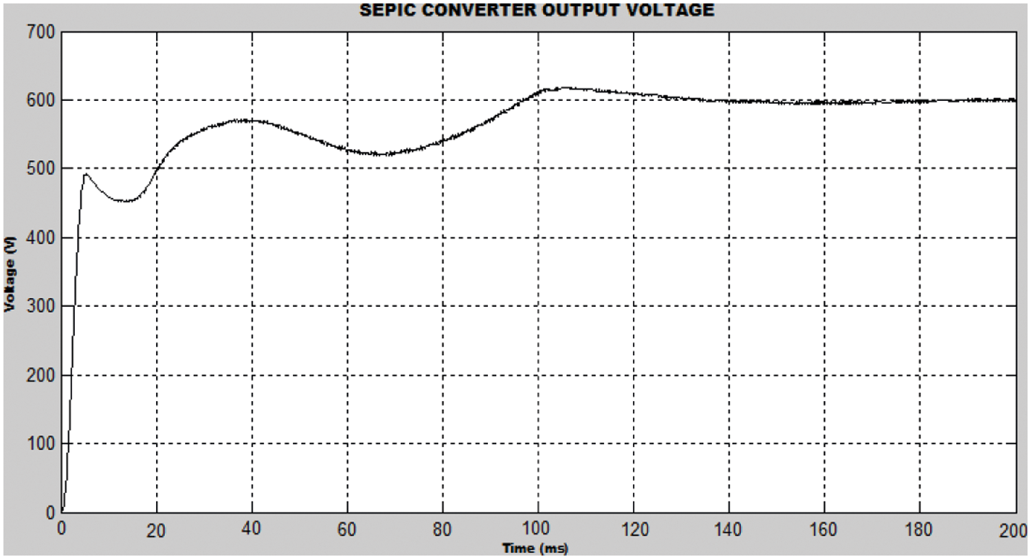
Figure 6: SEPIC Converter output with optimization
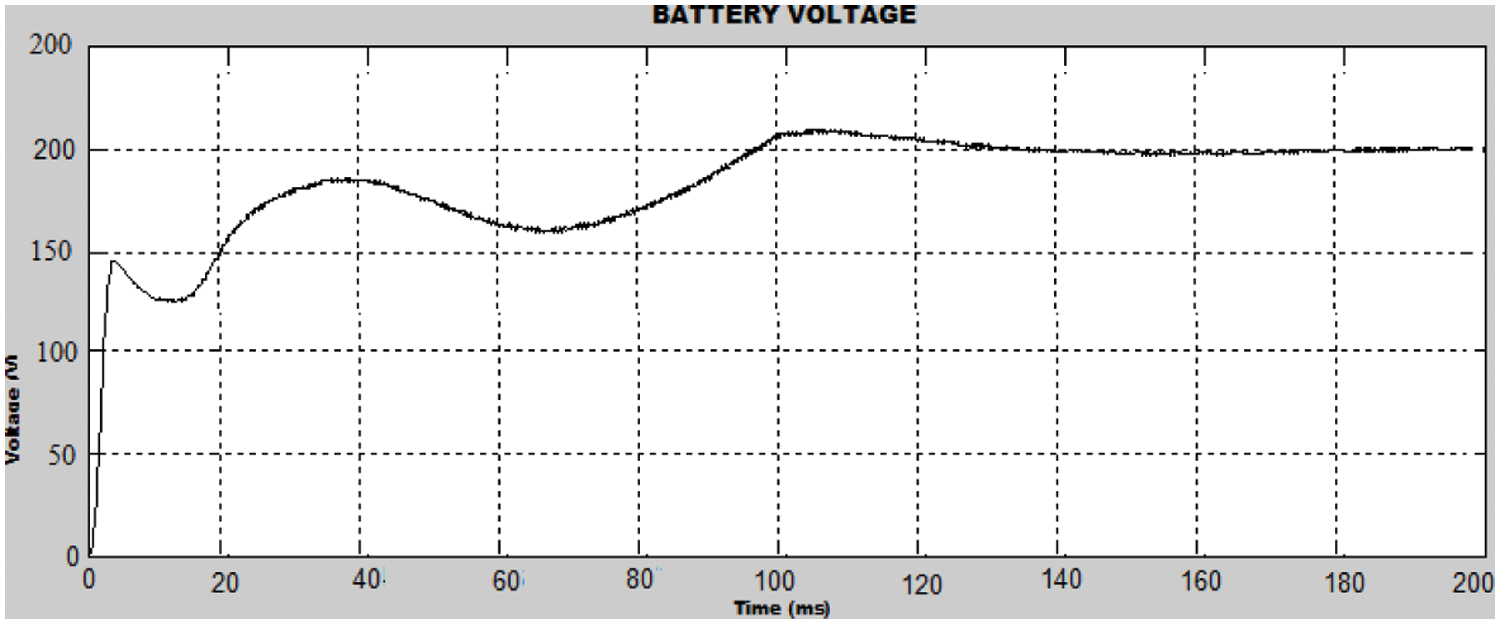
Figure 7: Battery voltage
The ranges of value are decided to change from the usable minimum and maximum operative ranges of the PV array and wind system for evaluating the behaviour of the system under these variations. In this case, the grid appears in a real time environment under the non-loading condition to measure the operational performance of the power conversion.
The stability of dc voltage is obtained with static amplitude of 600 V. With the GWO optimization, the source current is preserved with a THD (Total Harmonic Distortion) of 1.26% whereas 4.72% of THD is delivered without the optimization of GWO.
The output at wind turbine side with GWO optimized PI controller is described in Fig. 8.
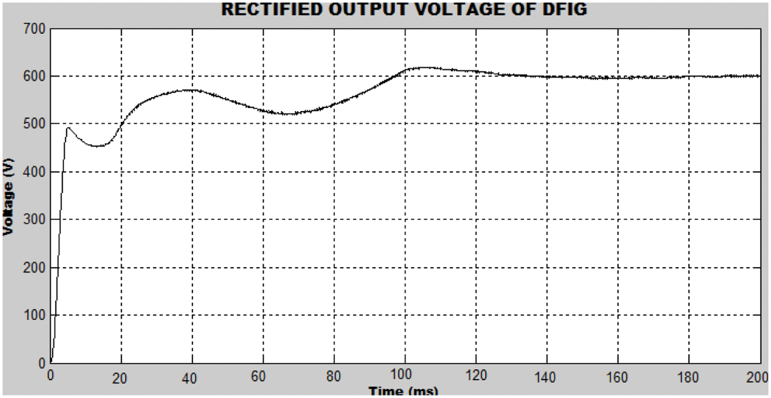
Figure 8: Output at Wind turbine side with GWO optimized PI controller
The voltage and current waveforms are depicted in Fig. 9 whereas the THD analysis waveform is depicted in Fig. 10, which indicate the efficient reactive power control at the grid side. The SEPIC converter voltage for GWO optimized PI controller is depicted in Fig. 11. The Figs. 12 and 13 represents the DC link voltage in battery and the DC link voltage with GWO-PI and PI controller.
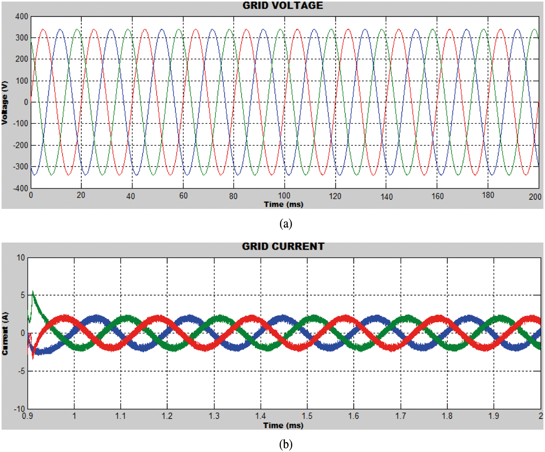
Figure 9: Output at grid side
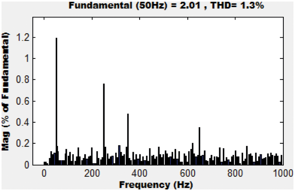
Figure 10: THD at the grid side
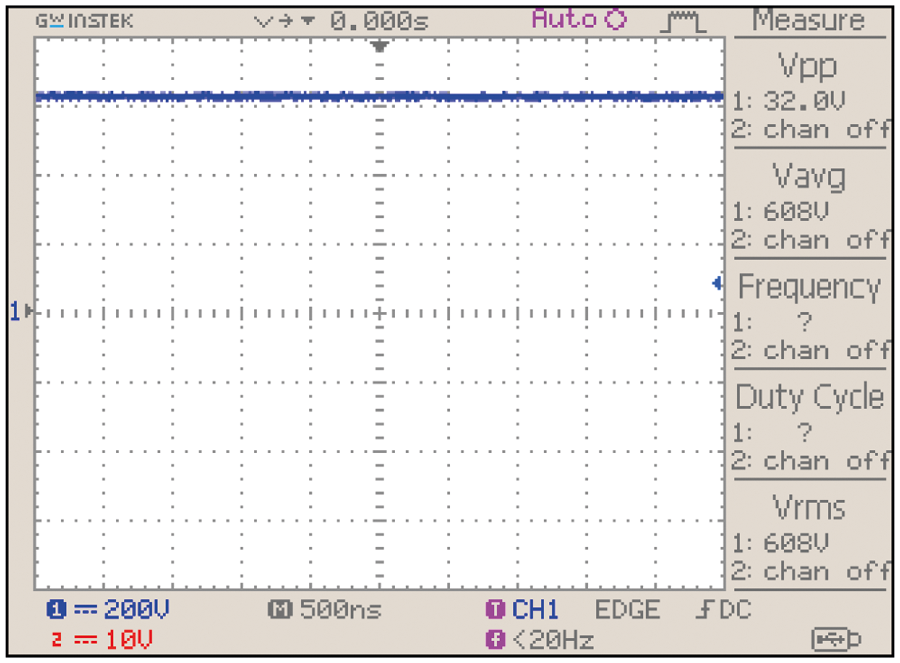
Figure 11: SEPIC converter voltage for GWO optimized PI controller
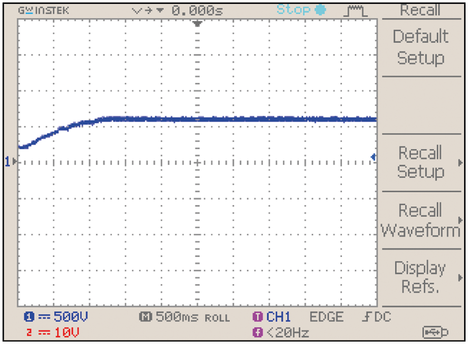
Figure 12: DC-link voltage in Battery
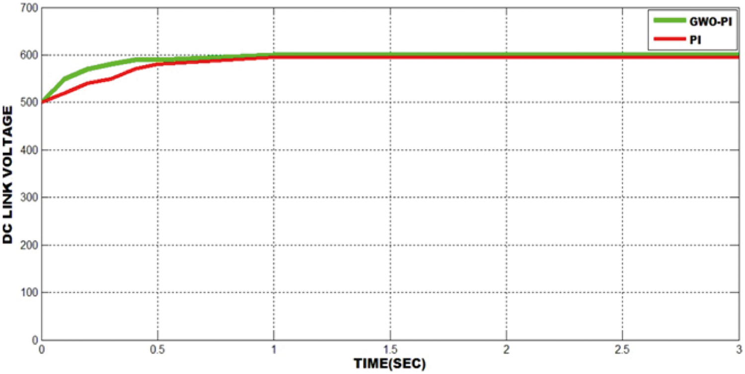
Figure 13: DC-link voltage with GWO-PI and PI Controller
The laboratory prototype of the PV-wind-Battery system is realized in FPGA (Field Programmable Gate Array) to analyse the significant properties of the developed power conversion system. A 1 kW PV, DFIG and batteries with GWO optimized PI converter is prepared. It utilizes the DC link voltage as the only feedback signal by using signal conditioning unit. Internal PWM blocks are required by the controllers to run the converter. The input-output pins are used for operating the power contactors via EM (Electromechanical) relays. The entire system programmed in FPGA Spartan 6E controller.
The voltage and current waveforms of the inverter for the developed hardware are given in Fig. 14. The sinusoidal line current, which is explicitly synchronized with the voltage indicates that only the active power is given to the grid. Further, the harmonic component of the current is also shown as less than 2%. The grid current THD is 1.8% when PI controller is optimized by GWO whereas it is 4.9% without the optimization of PI controller. The rise time (tr), peak time (tp) and steady state error (ess) are lessened with the aid of the PI controller. The minimization of objective function is achieved by GWO algorithm. The effectiveness of the optimized PI controller is verified with the proposed SEPIC converter.
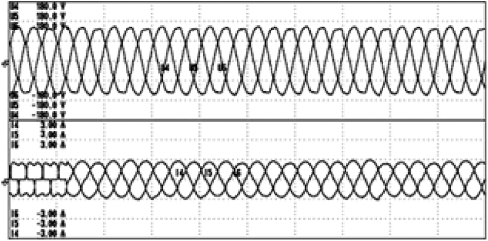
Figure 14: Voltage injected at the grid
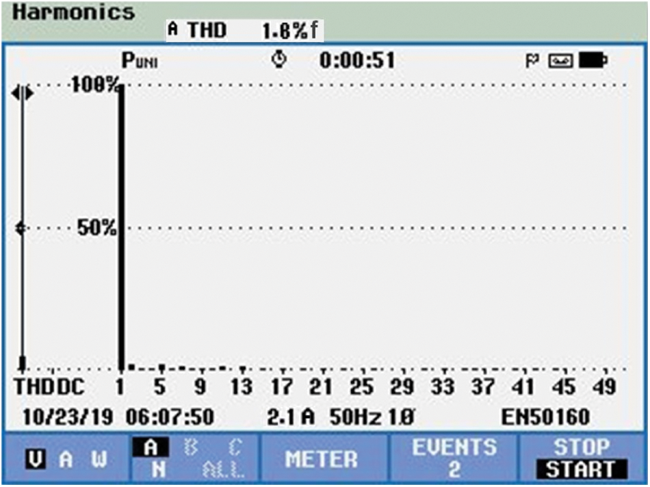
Figure 15: THD obtained with optimized PI controller
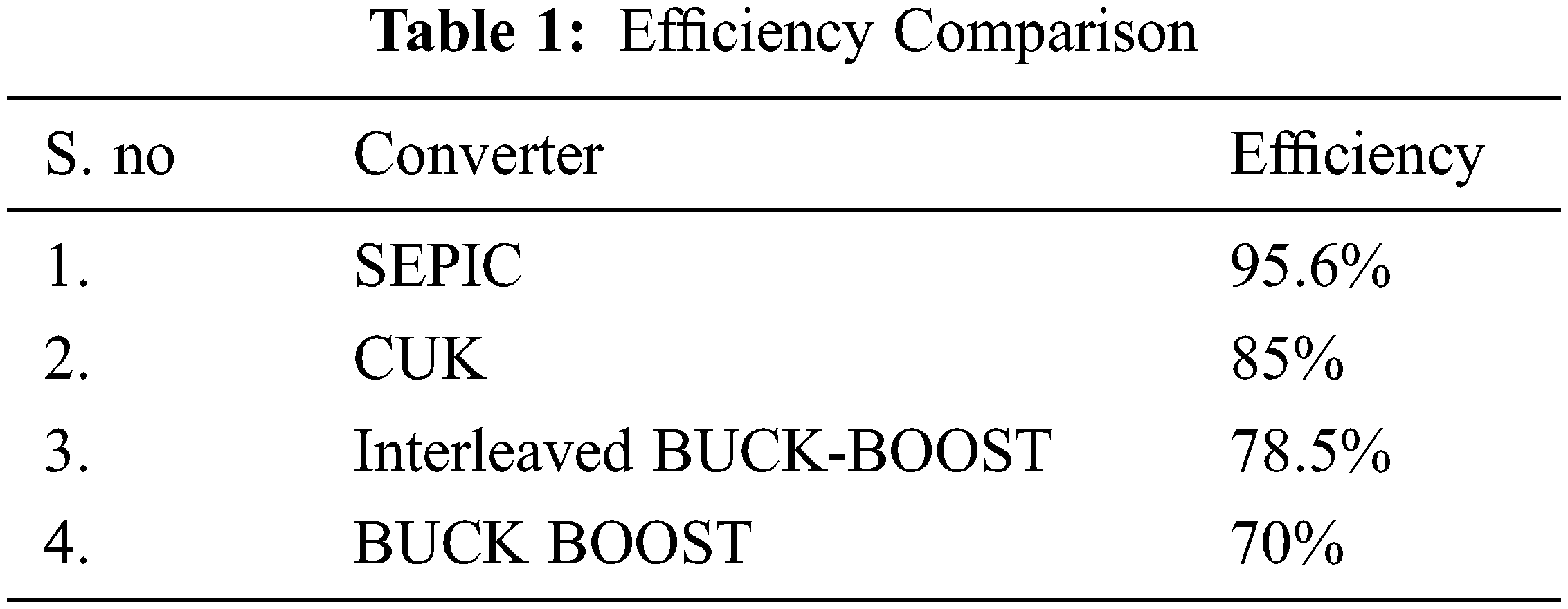
Thus the THD is maintained at low level as per IEEE current regulation. The results affirm the idea of independent control of the individual sources (PV, wind and Battery). The efficient control of solar voltage, rectified voltage of the wind generation unit are being tracked to get optimum power. In addition, the intelligent control for the SOC of battery satisfies the power sufficiency and ensures the consistent power supply. The efficiency of different converters with various output power is seen in Fig. 16, which proves that the proposed algorithm achieves 95.6% gain which is comparatively higher than the BUCK-BOOST, Interleaved boost and CUK controllers. Tab. 1. Give us the numerical details of the proposed topology.
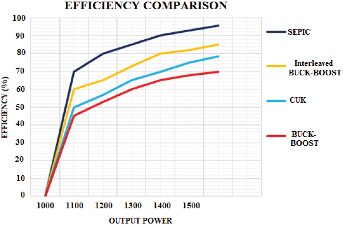
Figure 16: Comparison of Efficiency
Duty cycle variation is directly proportional to the output voltage magnitude. In this study, the input voltage of 200 V is fed to the SEPIC converter, which gives an output of 510 V for 70% duty cycle and 600 V for 85% duty cycle.
Tab. 2 give us the gain value of various converters under different duty cycle with 200 v of input voltage. For 65% duty cycle, the maximum output voltages of different converters are compared with the novel SEPIC converter, which give a maximum voltage of 600 V.
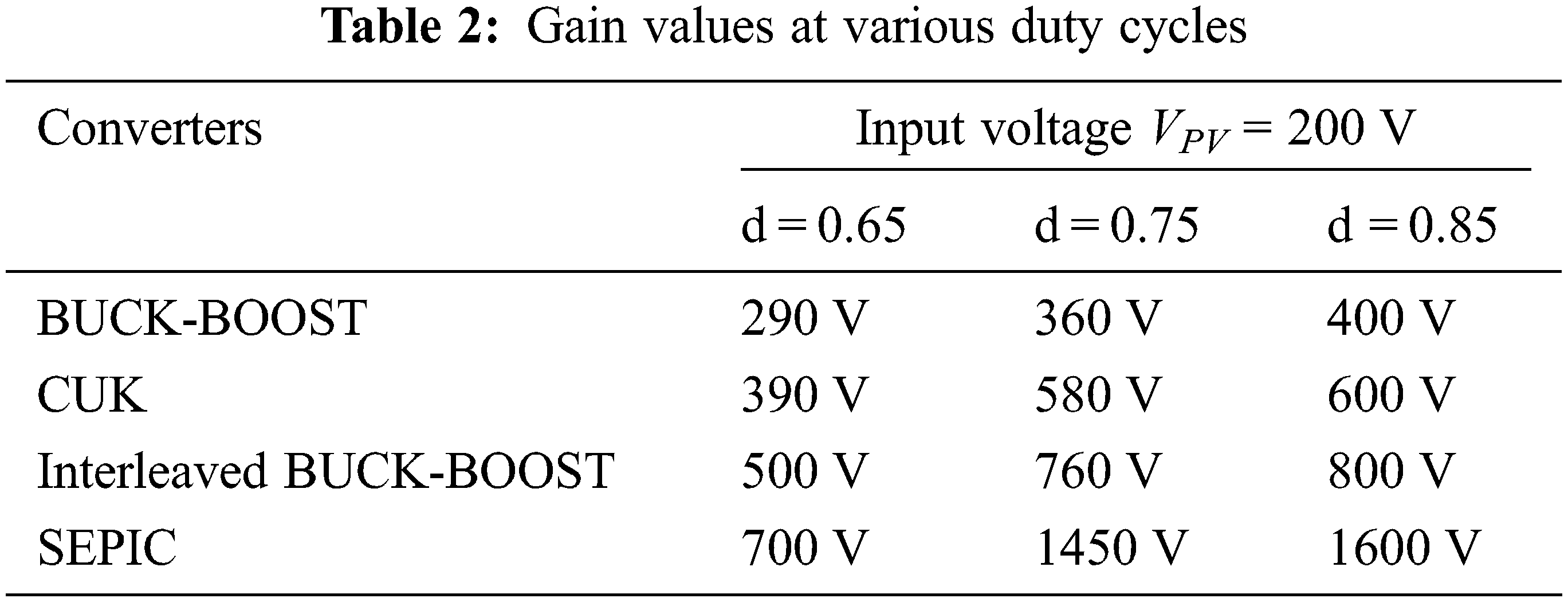
When, the duty ratio is increased to 85%, the gain of the converters increases. The gain of existing converters for 200 V input is compared with the proposed SEPIC converter. The gain of our proposed SEPIC converter is 50% greater than the Interleaved BUCK-BOOST converter with the maximum output voltage of 1600 V, which was eight times higher than the input voltage as shown in Fig. 17.
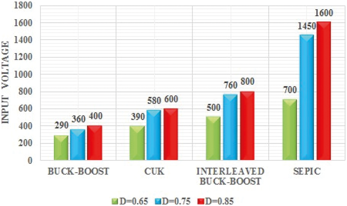
Figure 17: Output voltage comparison
A grid interactive PV-wind renewable power system is discussed in this work. This hybrid system has the ability to give consistent power with better reliability than the power sources, which have no battery backup. The PI controller of renewable system and the battery controller are employed to retain the fixed dc voltage under the power fluctuation in PV and wind turbines. The charging and discharging states of batteries are regulated by RNN to provide continuous power to the grid when the primary sources fail to meet the expected power output. The overall system description of the proposed model is presented with its converter and control schemes. The simulation and hardware results have validated the system feasibility. The power fluctuations in the hybrid system are effectively minimized by GWO controller. The tuning parameters are selected by reducing the IAE to improve the flexibility of the converter. For the step change in input power, the characteristics of the converter are measured and the simulation results are presented. In addition, the time domain parameters of the controllers are effectively minimized by using the optimized PI controller. Further, it is possible to extend this work with increased power rating by implementing the controller with other optimization approaches.
Funding Statement: The authors received no specific funding for this study.
Conflicts of Interest: The authors declare that they have no conflicts of interest to report regarding the present study.
1. A. Qazi, F. Hussain, N. A. B. D. Rahim, G. Hardaker, D. Alghazzawi et al., “Towards sustainable energy: A systematic review of renewable energy sources, technologies, and public opinions,” IEEE Access, vol. 7, pp. 63837–63851, 2019. [Google Scholar]
2. M. H. Nehrir, C. Wang, K. Strunz, H. Aki, R. Ramakumar et al., “A review of hybrid renewable/alternative energy systems for electric power generation: Configurations, control, and applications,” IEEE Transactions on Sustainable Energy, vol. 2, no. 4, pp. 392–403, 2011. [Google Scholar]
3. M. Faisal, M. A. Hannan, P. J. Ker, A. Hussain, M. Mansur et al., “Review of energy storage system technologies in microgrid applications: Issues and challenges,” IEEE Access, vol. 6, pp. 35143–35164, 2018. [Google Scholar]
4. C. Wang, H. Nehrir, F. Lin and J. Zhao, “From hybrid energy systems to microgrids: Hybridization techniques, configuration, and control,” in Proc. IEEE PES General Meeting, Minneapolis, MN, USA, pp. 1–4, 2010. [Google Scholar]
5. J. Esch, “High-power wind energy conversion systems: State-of-the-art and emerging technologies,” in Proc. of the IEEE, Gorakhpur-India, vol. 103, no. 5, pp. 736–739, 2015. [Google Scholar]
6. M. J. Hossain, H. R. Pota, M. A. Mahmud and M. Aldeen, “Robust control for power sharing in microgrids with low-inertia wind and PV generators,” IEEE Transactions on Sustainable Energy, vol. 6, no. 3, pp. 1067–1077, 2015. [Google Scholar]
7. Zaheeruddin and Munish Manas, “Renewable energy management through microgrid central controller design: An approach to integrate solar, wind and biomass with battery,” Energy Reports, vol. 1, pp. 156–163, 2015. [Google Scholar]
8. P. S. Kumar, R. P. S. Chandrasena, G. N. Srinivas, V. Ramu and K. V. S. M. Babu, “Energy management system for small scale hybrid wind solar battery based microgrid,” IEEE Access, vol. 8, pp. 8336–8345, 2020. [Google Scholar]
9. A. Merabet, K. T. Ahmed, H. Ibrahim, R. Beguenane and A. M. Ghias, “Energy management and control system for laboratory scale microgrid based wind-PV-battery,” IEEE Transactions on Sustainable Energy, vol. 8, no. 1, pp. 145–154, 2017. [Google Scholar]
10. B. Priyadharshini, V. Ganapathy and P. Sudhakara, “An optimal model to meet the hourly peak demands of a specific region with solar, wind and grid supplies,” IEEE Access, vol. 8, pp. 13179–13194, 2020. [Google Scholar]
11. F. Chishti, S. Murshid and B. Singh, “LMMN based adaptive control for power quality improvement of grid intertie wind-PV system,” IEEE Transactions on Industrial Informatics, vol. 15, no. 9, pp. 4900–4912, 2019. [Google Scholar]
12. A. A. A. Radwan and Y. A. R. I. Mohamed, “Grid-connected wind-photovoltaic cogeneration using back-to-back voltage source converters,” IEEE Transactions on Sustainable Energy, vol. 11, no. 1, pp. 315–325, 2019. [Google Scholar]
13. L. Xu, X. Ruan, C. Mao, B. Zhang and Y. Luo, “An improved optimal sizing method for wind-solar-battery hybrid power system,” IEEE Transactions on Sustainable Energy, vol. 4, no. 3, pp. 774–785, 2013. [Google Scholar]
14. T. Hirose and H. Matsuo, “Standalone hybrid wind-solar power generation system applying dump power control without dump load,” IEEE Transactions on Industrial Electronics, vol. 59, no. 2, pp. 988–997, 2012. [Google Scholar]
15. S. A. Daniel and N. A. Gounden, “A novel hybrid isolated generating system based on PV fed inverter-assisted wind-driven induction generator,” IEEE Transactions Energy Converters, vol. 19, no. 2, pp. 416–422, 2004. [Google Scholar]
16. S. K. Tiwari, B. Singh and P. K. Goel, “Design and control of autonomous wind-Solar System with DFIG feeding 3-phase 4-wire loads,” IEEE Transactions on Industry Applications, vol. 54, no. 2, pp. 1119–1127, 2017. [Google Scholar]
17. T. Wang, D. O'Neill and H. Kamath, “Dynamic control and optimization of distributed energy resources in a microgrid,” IEEE Transactions on Smart Grid, vol. 6, no. 6, pp. 2884–2894, 2015. [Google Scholar]
18. K. Karthikeyan, S. K. Patnaik, M. Baskar and E. Jeyashree, “A dsPIC based optimal sizing of solar PV plant using ultra capacitors for transient power delivery,” Microprocessors and Microsystems, Issue No - 2019, vol. 71, pp. 1–9, Sep 2019. [Google Scholar]
19. M. H. Prabhu and K. Sundararaju, “Power quality improvement of solar power plants in grid connected system using novel resilient direct unbalanced control (RDUC) technique,” Microprocessors and Microsystems, vol. 75, 2020. [Google Scholar]
20. D. Baptista, S. Abreu, C. Travieso-Gonzalez and F. Morgado-Dias, “Hardware implementation of an artificial neural network model to predict the energy production of a photovoltaic system,” Microprocessors and Microsystems, vol. 49, pp. 77–86, 2016. [Google Scholar]
21. W. Qi, Z. Yu, R. Ye, Z. Lin, and Y. Tang, “An ordered curtailment strategy for offshore wind power under extreme weather conditions considering the resilience of the grid,” IEEE Access, vol. 7, pp. 54824–54833, 2019. [Google Scholar]
 | This work is licensed under a Creative Commons Attribution 4.0 International License, which permits unrestricted use, distribution, and reproduction in any medium, provided the original work is properly cited. |