DOI:10.32604/iasc.2022.024482
| Intelligent Automation & Soft Computing DOI:10.32604/iasc.2022.024482 | |
| Article |
Optimum Tuning of Photovoltaic System Via Hybrid Maximum Power Point Tracking Technique
1Department of EEE, Lourdes Mount College of Engineering and Technology, Mullanganavilai, Tamil Nadu, 629195, India
2Department of EEE, St. Xavier’s Catholic College of Engineering, Nagercoil, Tamil Nadu, 629003, India
*Corresponding Author: M. Nisha. Email: nishajournals2021@gmail.com
Received: 19 October 2021; Accepted: 17 January 2022
Abstract: A new methodology is used in this paper, for the optimal tuning of Photovoltaic (PV) by integrating the hybrid Maximum Power Point Tracking (MPPT) algorithms is proposed. The suggested hybrid MPPT algorithms can raise the performance of PV systems under partial shade conditions. It attempts to address the primary research issues in partial shading conditions in PV systems caused by clouds, trees, dirt, and dust. The proposed system computes MPPT utilizing an innovative adaptive model-based approach. In order to manage the input voltage at the Maximum PowerPoint, the MPPT algorithm changes the duty cycle of the switch in the DC-DC (Direct Current-Direct Current) converter (MPP). Temperature as well as fluctuations in output power will induce alteration in PV panel operating current and voltage. MPPT is gaining a lot of interest as a key optimization sector to solve this optimization problem in PV systems. A hybrid optimization approach is utilized to produce a combination of the Cuckoo Search-Perturb & Observe (CS-PO) and incremental conductance-particle swarm optimization (IC-PSO) algorithms. After measuring the voltage and current from the solar system, this optimization computes the output power. The IC-PSO optimization achieves Maximum PowerPoint Tracking with increased efficiency of 99.5%. The proposed optimization techniques are established in the MATLAB Simulink program to validate its efficiency.
Keywords: PV system; partial shading conditions; maximum power point tracking (MPPT); DC-DC converter; cuckoo search (CS) algorithm; perturb observe (PO); particle swarm optimization (PSO); incremental conductance (IC)
To address air pollution in the environment caused by Carbon dioxide (CO2) emissions, renewable energy is used to generate electricity as an alternate source. Due to its enormous availability and inexhaustibility, photovoltaic solar power has become one of the most popular renewable energy sources [1]. Solar cells, on the other hand, have lower conversion efficiency, and a photovoltaic (PV) array’s output power is heavily reliant on irradiance and temperature. In order to completely leverage the PV array’s efficacy, the maximum power point tracking (MPPT) circuit would be connected to both the PV array and the load [2]. The usage of electrical PV systems in power technologies is well-known and ubiquitous. PV technology converts the energy stored in a photon of light into electricity. PV systems are very much frequently employed in the field of electric power generation. This technique has been used to generate the power of solar, solar vehicle construction, battery charging, water pumping, satellite power systems, and other applications [3]. Surrounding obstructions with irregular geometries, such as trees, overhangs, chimneys, telephone poles, and other objects, might produce shade problems in the system. This phenomenon is known as partial shading [4]. The shading effect has a significant non-linear impact on the performance of PV systems. Due to non-uniform solar irradiation levels, the local maximum power point (LMPP) and global maximum power point (GMPP) are dependent on the power-voltage (PV) properties [5].
Hill climbing (HC), perturb and observation (P&O) and incremental conductance (IC) are the examples of traditional MPPT techniques that were reviewed and improved. P&O is the most pretentious of all MPPTs displaying firm merging to the maximum power point (MPP) [6]. To enhance the PV framework execution, the P&O approach selects an acceptable advance size [7]. The most common direct control method is the incremental conductance approach. The MPPT algorithm is now being developed with an emphasis on continuous optimization of PV system mathematics and control systems [8]. The incremental conductance approach is the most prevalent direct control method. The MPPT method is currently under development, with a focus on continuous improvement of PV system mathematics and control systems [9]. The incremental conductance (IC) technique was devised to improve tracking accuracy and dynamic performance under quickly varying situations. It is based on the fact that the PV array power vs. voltage curve slope is zero at the MPP. The duty cycle of the system swings during steady-state, resulting in power losses [10]. Particle Swarm Optimization (PSO) is a robust and flexible methodology fit to deal with this nonlinear characteristic of solar panels in the sense of avoiding stagnation at a local optimum [11]. With its basic structure, simple implementation and quick processing capability, Particle Swarm Optimization (PSO) have great potential [12]. The Particle Swarm Optimization technique can solve the power system optimization problem [13,14] because of its speedy convergence, multi-particle parallel processing, and simpler of using it. The use of the particle swarm optimization technology in multi-peak PV array MPPT is detailed in the literature [15], and it is demonstrated to be simple and effective. Cuckoo Search (CS), a revolutionary metaheuristic search algorithm, appears to be very productive and has the potential to beat existing methods [16]. A pattern correlates to a nest in the Cuckoo algorithm, and each unique property of the pattern correlates to a Cuckoo-egg [17,18].
The following is a breakdown of the paper’s structure. The present scheme is briefly established in Section 2, followed by modeling of the PV array in Section 3. The paper’s recommended algorithms are explained in Section 4. The findings of the conventional system are discussed in Section 5. At last, in Section 6, the conclusion is offered.
The block diagram of the proposed system is shown in Fig. 1. The solar PV array’s output is sent into the DC-DC Converter that converts DC (direct current) power into the level required by the load. This DC output is converted into Alternating Current (AC) by the inverter and provided to the load. The current and voltage from the PV array are received by the MPPT controller which then sends the output to the converter. The voltage and current are sensed using the algorithm.
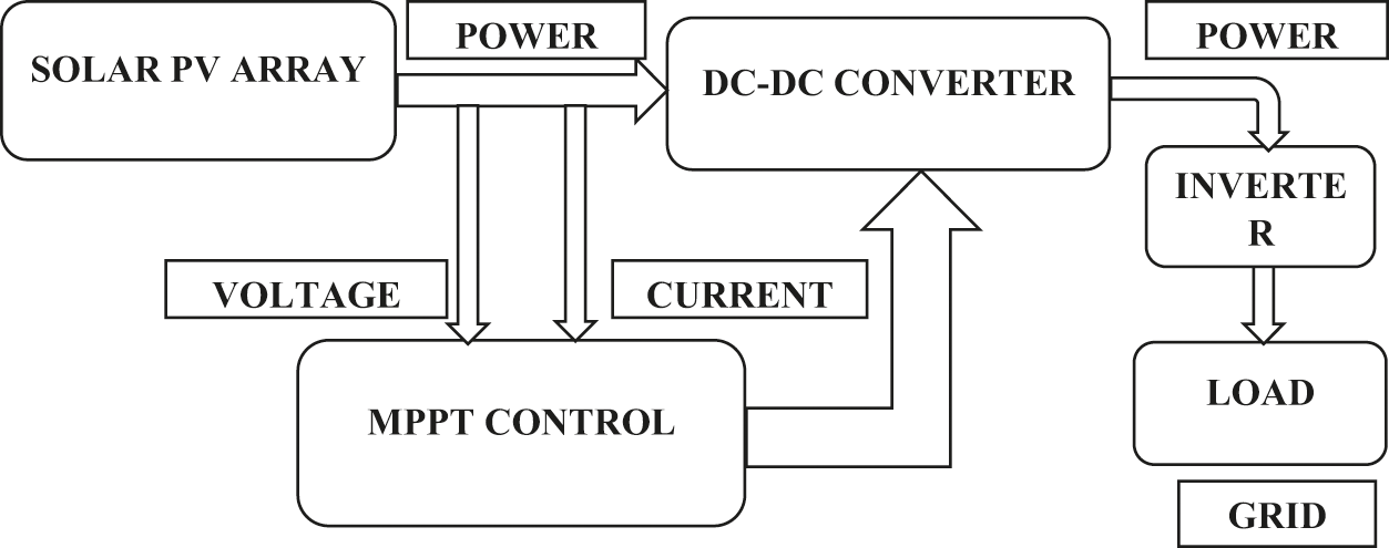
Figure 1: Block diagram of the proposed system
A photovoltaic (PV) array is a group of solar panels that are linked electrically to make a big PV installation (PV system). Semiconductor materials like silicon is used to construct PV cells. Because a single PV cell’s output voltage/current is so low, many cells are coupled to increase the output voltage/current. Electrons are unscrewed from the atoms in the semiconductor material when light energy hits the solar cell. Solar energy will be transformed into direct current (DC) power using photovoltaic panels and cells. Solar panels in single PV are connected in the same manner as PV cells in single panel. Although in some instances, a series connection is used to enhance the output voltage. Electrical connections between panels in an array can be made in series, parallel or a combination of the two.
When electrical conductors are connected to the positive and negative sides of an electrical circuit, electrons are collected in the form of an electric current. This electricity serves as a source of load power. A single module’s energy output is inadequate to meet the needs. An inverter converts DC electricity into alternating current, which powers the motor, loads, or lights in a PV array. A PV array’s single module is connected in series to achieve greater voltages before being linked in parallel to increase the system’s current value.
Efficiency of PV cell: The effectiveness of a photovoltaic cell is defined as the ratio of peak solar power to solar power intake. It is given by,
where, Vpp – Voltage at apex power.
Ipp – Current at apex power.
Is – Intensity of solar.
A1 – Area on which solar radiation falls.
The efficiency of a PV system can be enhanced by using several MPPT methods to track the system’s maximum power under various environmental conditions.
A DC-DC converter connects the PV module to the load, converting the uncontrolled DC input into a controlled DC output at a predetermined voltage level. These converters’ efficiency ranges from 88.20% to 96.550%. To step up the voltage to the higher level required by the load, the suggested methodology employs a boost converter. This might be done by storing the energy in an inductor and then delivering it at a higher voltage to the load.
Because the solar PV module’s efficiency is around 13%, it is best to run it at full power so that the greatest amount of electricity is delivered to the load regardless of temperature or insolation. A maximum power point tracker (MPPT) is a device that gathers and delivers the maximum power from a solar PV module to a load. Maximum power point tracking is a technique for maximizing the output of one or more solar panels (MPPT). The source’s load impedance is modified and regulated at peak power, allowing the required power to be transmitted. A dc/dc converter is put between the load and the solar PV module to reach the best PowerPoint. The duty cycle of the converter is modified until the peak power point is reached.
The inverter is a piece of electronic equipment that converts DC electricity from a converter to AC power for grid use. Three single-phase semiconductor switches make up the three-phase inverter. Pulse Width Modulation (PWM) pulse generators offer the pulses to these switches. It works by changing the duty cycle of a square wave while keeping the period constant.
3 Mathematical Modeling of PV Array
PV modules are made up of PV cells that are connected in series or parallel to build PV arrays, which is shown in Fig. 2. Photovoltaic (PV) systems employ them to generate electricity. The circuit that corresponds to the PV array is shown below.
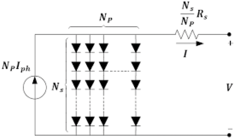
Figure 2: Equivalent circuit of PV array
The solar cell’s voltage current characteristic equation is
Here, Ip – Photo current
Isc – Short circuit current
Tp – Operating temperature
Ir – Solar irradiance
Reverse saturation current of module (Irs) is given by
where, q is known as electron’s charge (1.6 * 10−19C)
Voc is open circuit voltage
Ms is no of cells connected in series
r is ideality factor of diode
k is Boltzmann’s constant (
The saturation current of the module varies with the cell’s temperature. The equation encapsulates it
where, Tr is normal temperature = 298.15 K
Ego is energy band gap of semiconductor
The PV module’s output current is given by
where,
where,
Mp is the no of PV modules connected in series.
Rs is the resistance in series.
Rsh is the resistance in shunt.
Pt is the thermal voltage of diode (V).
4 Proposed Optimization Techniques
Among various algorithms that are used to optimize the output of PV array, proposed method uses following hybrid algorithms
• Perturb and Observe algorithm (PO) and Cuckoo Search Optimization (CS)
• Incremental Conductance (IC) and Particle Swarm Optimization (PSO)
The objective function used for optimization is
where, β = 3/2
4.1 Perturb and Observe Algorithm (PO)-Cuckoo Search Optimization (CS)
Terms of speed and precision, the P&O (Perturb and Observe Algorithm) is one of the most common algorithms for monitoring the MPPT of PV systems. Changing the PV voltage (VPV) and monitoring the change in PV power is how the standard P&O algorithm [19] works and is flowchart is shown in Fig. 3. If a perturbation causes the PV’s output power to increase (drop), the following perturbation is formed in the same (opposite) direction. The duty cycle is generated using the P&O MPPT algorithm [20].
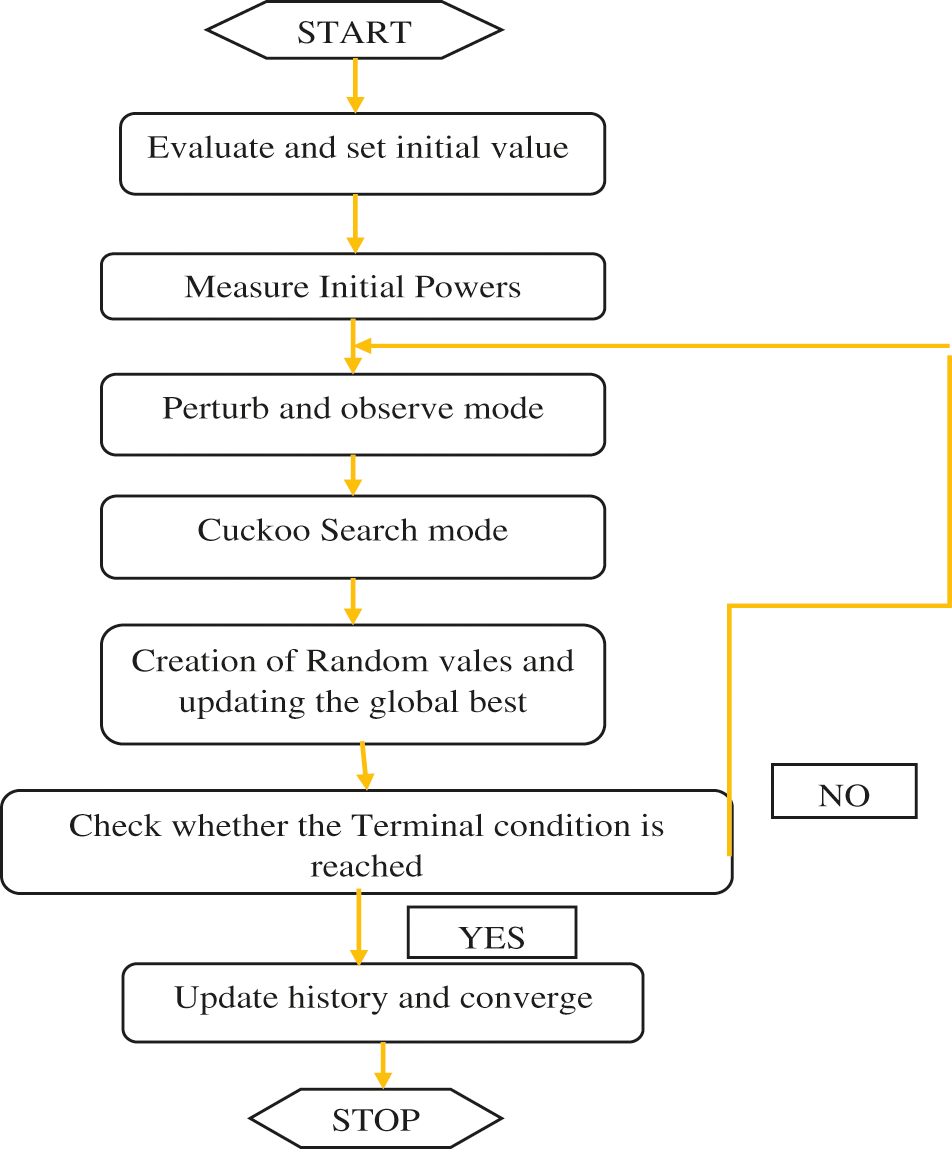
Figure 3: Flowchart of hybrid PO and CS optimization technique
The CS algorithm is according to cuckoo bird reproductive behaviour. Cuckoos are parasitic birds that lay their eggs in other birds’ nests instead of building their own. This strategy is according to the natural effectiveness of the cuckoo [21]. The motion given by the Levy formulas [22] is the foundation of this technique. The flowchart of proposed hybrid P&O and CS optimization is shown above. The efficiency produced by this algorithm is equal to 95.7%.
4.2 Incremental Conductance (IC)-Particle Swarm Optimization (PSO)
At greatest power, the slope of the PV characteristics in INC is 0, and there is no theoretically perturbation when the MPP is obtained. As a result, oscillations are reduced [23]. The PSO approach was developed by modelling the social attributes of a bird colony [24]. The basic PSO algorithm for next iteration is given by [25].
The combined flowchart of proposed hybrid Incremental conductance and Particle swarm optimization algorithm is shown in Fig. 4. The efficiency produced by this hybrid algorithm will be equal to 99.5% which is better efficient than hybrid (Particle swarm and Cuckoo Search Algorithm) PO-CS algorithm as the voltage produced in this method can be varied during the incremental algorithm process. Thus, by improving voltage the efficiency produced will be improved.
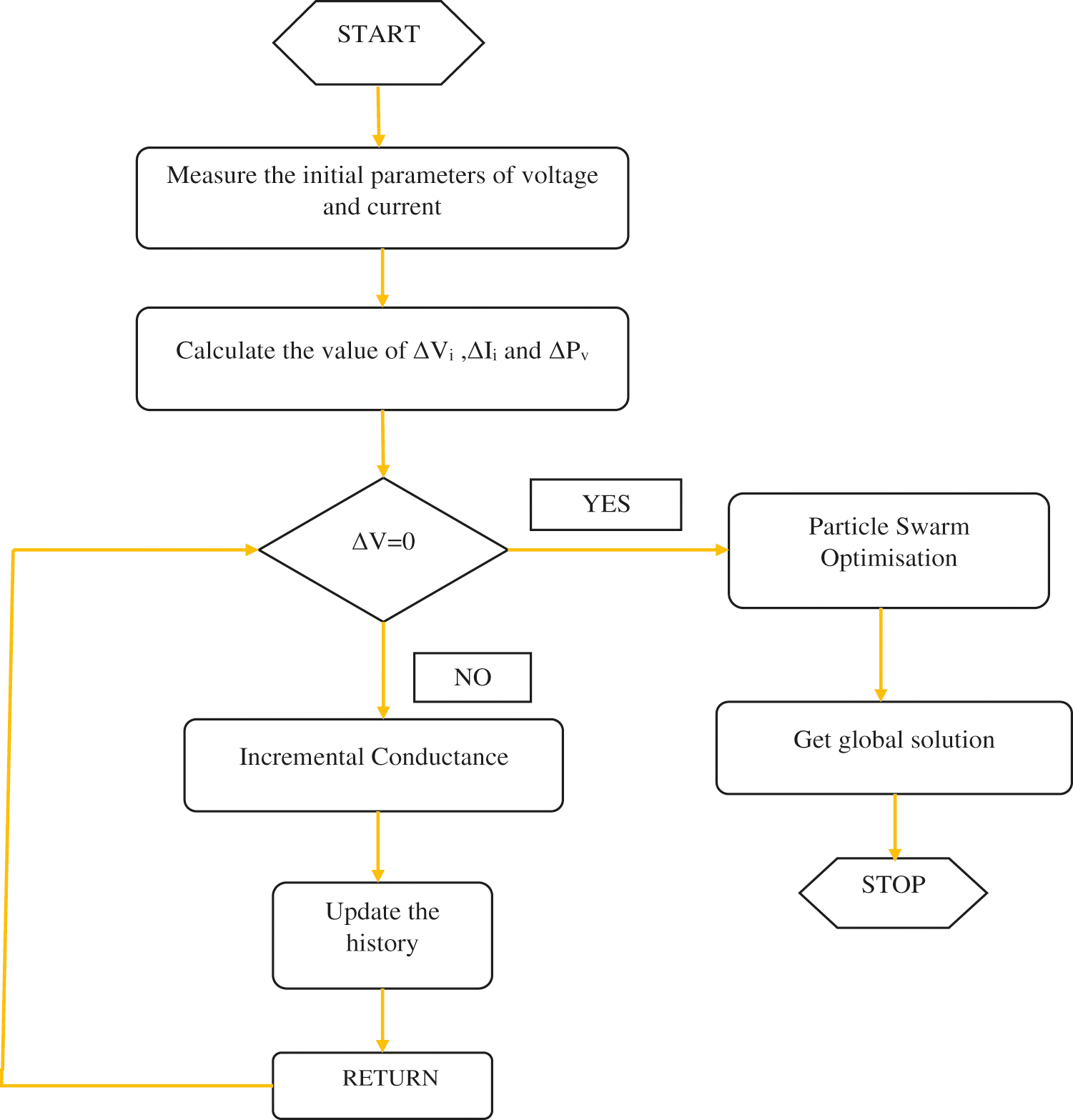
Figure 4: Flowchart of hybrid IC & PSO optimization technique
Using these proposed algorithms, voltage, the PV system’s current and power are calculated to estimate the system’s efficiency.
5 Simulation Results and Discussion
The proposed PV grid-connected inverter consists of a PV array of 10 kW followed by two-level inverter; a DC-link capacitor is inserted between them for coupling. In MATLAB software, simulations are conducted on Hybrid MPPT algorithm of photovoltaic system in order to validate the proposed method. Fig. 5 displays a Simulink proposed system model.
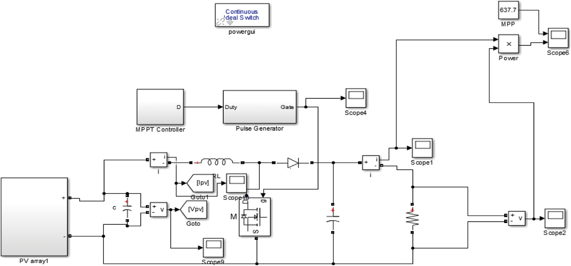
Figure 5: Simulink model of the proposed system
To ensure that the circuit comparison can be established precisely, all buck and boost converter simulation data has been documented. The primary comparisons to take into account are input and output voltages, current, and power. Based on the literature, the circuit’s complexity and simplicity have been determined. A step can alter in insolation is supplied at a simulation time of 0.01 s by increasing insolation from 500 W/m2 to 1000 W/m2 at a fixed ambient temperature of 65°C to test the converter’s durability. This MATLAB simulation model shows the DC-DC boost converter, single phase grid tie inverter, PV module, PSO-IC and PO-CS MPTT algorithm. By adjusting insolation from 500 W/m2 to 1000 W/m2 at a fixed ambient temperature of 65°C, a step change in insolation is delivered at a simulation time of 0.01 s to test the converter’s durability.
The PV array system’s specification and parameters are shown in Tab. 1. These simulations include the implementation of modified CS-PO and IC-PSO algorithms for CPG mode operation, as well as the MPPT employing CS-PO and IC-PSO algorithms. At the same irradiance and temperature circumstances, the suggested algorithm performs well both below and beyond the reference power limit.
A PV array made up of parallel strings of PV modules is implemented. Each string is made up of a succession of modules. Signals should be sent from voltage blocks with the required voltage. If voltage visibility is grid, then go to voltage tag Visibility block must be used to define the visibility of the input voltage tag.
Figs. 6–8 illustrates the evolution of errors of current, voltage and power, respectively. In this test, it’s easy to see the enormous advantage of this algorithm over classical techniques, such as CS-PO and IC-PSO algorithms, as there are no steady state oscillations with the implemented method.
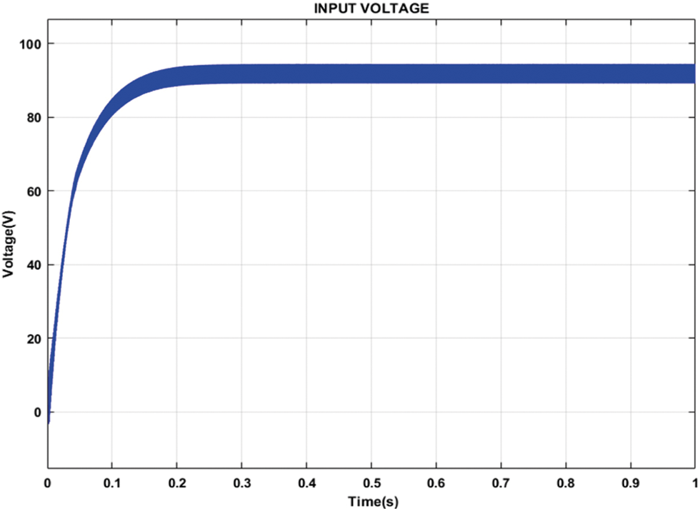
Figure 6: Input voltage of PV array system
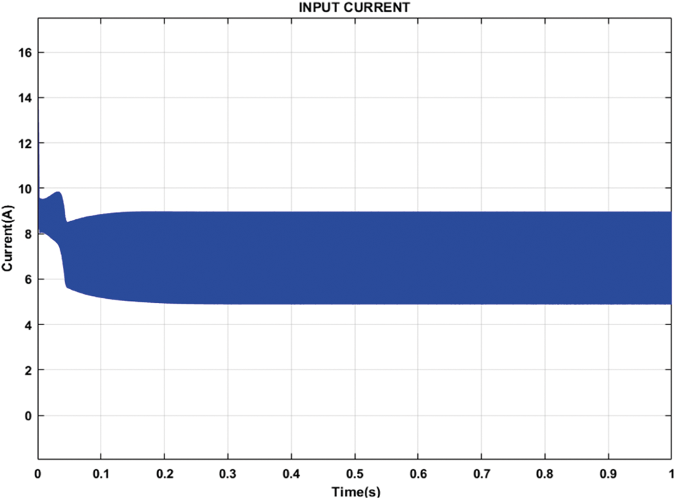
Figure 7: Input current of PV array system
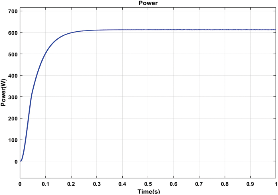
Figure 8: Input power of PV array system
Fig. 8 shows the output waveforms for PV system’s power. The result of study demonstrates that the convergence time of 0.02 s samples (equal to 1 s) is outstanding, and there will be no oscillations after the MPP algorithm is reached. The particle search is noticeable in the first iterations, the particles start from their initial random positioning and rapidly evolve to the MPPT controller.
In Fig. 9 shows the output waveform of current. The waveforms clearly show that IC-PSO performs better in terms of stability and current extraction from a solar PV panel. CS-P&O show worse performance of irradiation level. CS-P&O show high overshoot at each irradiation level is compared to IC-PSO. CS-P&O have a low response time and not stable under dynamic test condition. IC-PSO shows the best efficiency in terms of fast response time and reduced overshoot at the time of change in irradiation. IC-PSO is much better as compared with CS-P&O current waveform, but not as good as CS-P&O in terms of reduced overshoot extraction from a PV panel.
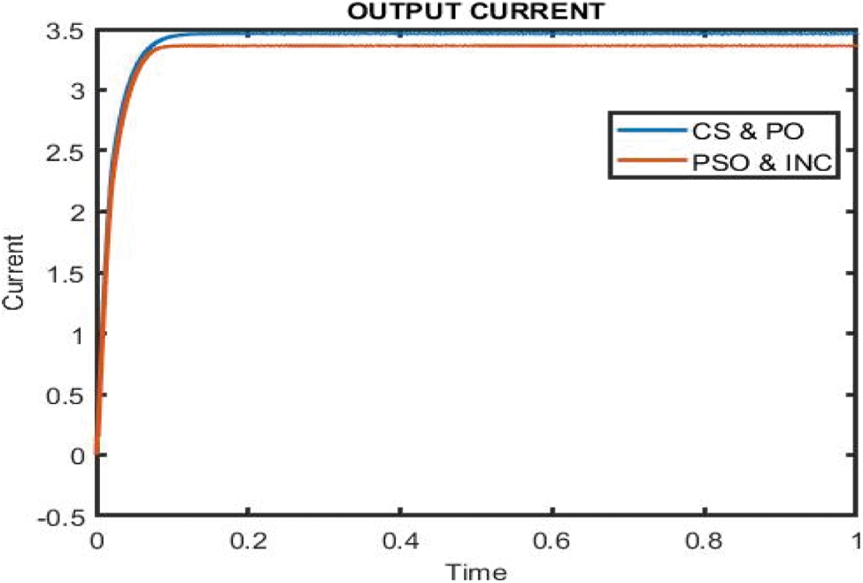
Figure 9: Performance analysis of current waveform using IC-PSO and CS-P&O algorithm
In Fig. 10 depicts the output voltage waveform. The waveforms clearly show that IC-PSO performs better in terms of stability and voltage extraction from a solar PV panel. CS-P&O show worse performance of irradiation level. CS-P&O show high overshoot at each irradiation level is compared to IC-PSO. CS-P&O have a low response time and not stable under dynamic test condition. IC-PSO shows the best efficiency in terms of fast response time and reduced overshoot at the time of change in irradiation. IC-PSO is much better as compared with CS-P&O voltage waveform, but not as good as CS-P&O in terms of reduced overshoot extraction from a PV panel.
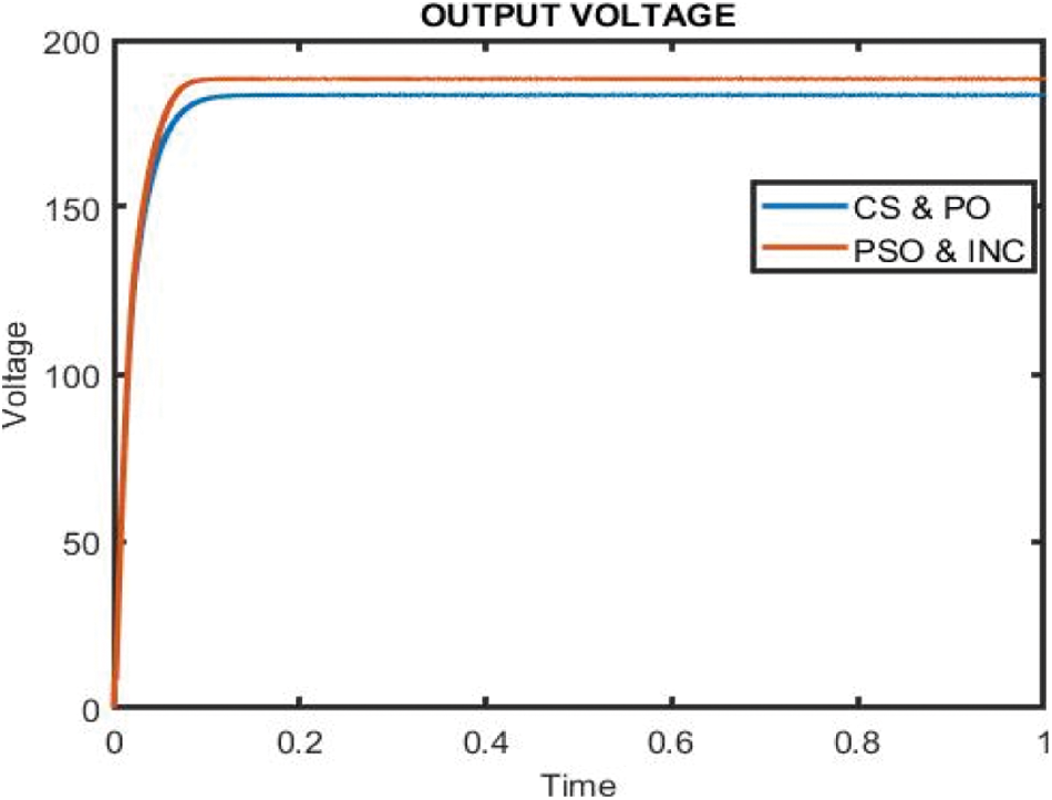
Figure 10: Performance analysis of voltage waveform using IC-PSO and CS-P&O algorithm
In Fig. 11 depicts the output power waveform. The waveforms clearly show that IC-PSO performs better in terms of stability and power extraction from a solar PV panel. CS-P&O show worse performance of irradiation level. CS-P&O show high overshoot at each irradiation level is compared to IC-PSO. CS-P&O have a low response time and not stable under dynamic test condition. IC-PSO shows the best efficiency in terms of fast response time and reduced overshoot at the time of change in irradiation. IC-PSO is much better as compared with CS-P&O power waveform, but not as good as CS-P&O in terms of reduced overshoot extraction from a PV panel.
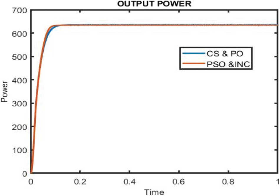
Figure 11: Performance analysis of power waveform using IC-PSO and CS-P&O algorithm
The MPPT controller based on IC-PSO calculates the correct current and Voltage (Voc) accordingly, corresponding to maximum power point till t = 0.01 s, the point at which shading occurs. The PV suddenly lowers from its optimal value when abrupt shift of operating current by shade occurs. The MPPT algorithm which is based on the IC-PSO method will be re-initialized. With pin point accuracy, the MPPT controller calculates the global new current corresponds to the Maximum Power Point (MPPT). Furthermore, the DC outcome of the power waveform is nearly identical to the output power waveform. Performance analysis of current, voltage and power waveform is shown in Fig. 12.
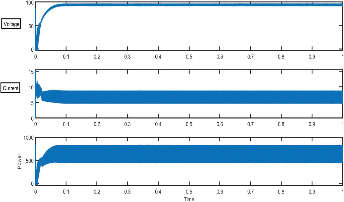
Figure 12: Performance analysis of current, voltage and power waveform
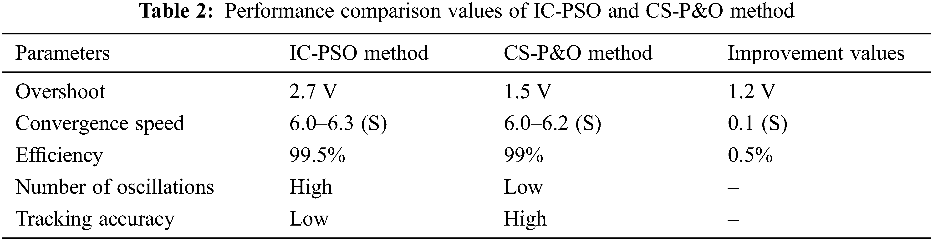
According to the findings, the study made considerable improvements in convergence speed and tracking accuracy, as well as a significant reduction for rapidly shifting weather conditions, the rate of overshoot and the number of oscillations. The system’s overall performance is also boosted. Tab. 2 shows the improvement values obtained using the IC-PSO and CS-P&O approaches.
Due to the frequent shifting of the duty cycle with each step in the traditional MPP (Maximum Power Point) method, there is a lot of fluctuation in the power curve of SPV. However, after each iteration, the IC-PSO algorithm produces a steady duty cycle with minimal changes in the power curve of SPV, as shown in Fig. 13, which gives a clearer picture of the IC-PSO algorithm’s viability. The duty cycles are constantly computed for the accurate tracking of new MPP during rapid variations or changes in irradiation from 1000 W/m2 as shown in Fig. 13.
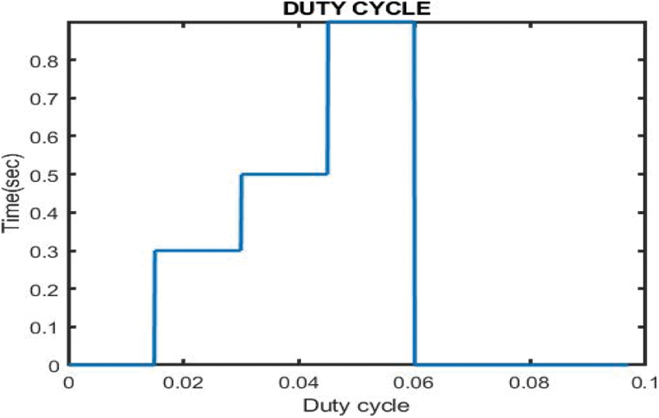
Figure 13: Comparative analysis of proposed duty cycle on IC-PSO algorithm
First search location in each iteration cycle is explored by CS-P&O (Cuckoo Search-Perturb and observe) optimization algorithm and then by domain IC-PSO (Incremental Conductance-Particle Swarm Optimization) algorithm. The simulation outcomes are compared to indicate that the benefits of this CS-P&O (Cuckoo Search-Perturb and Observe) optimization are excellent accuracy in diverse optimization techniques, good convergence, and low performance. Propose the IC-PSO (Incremental Conductance-Particle Swarm Optimization) algorithm technique for higher performance.
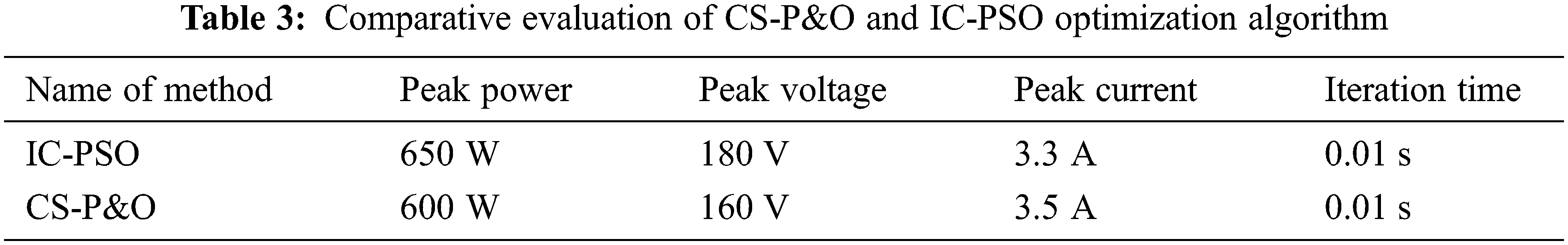
Tab. 3 shows the implementation of several algorithms under partial shading conditions, and it is obvious that the IC-PSO method monitors the greatest power after some transient responses that occur within the first 0.01 s. There are also a lot of iterations before it reaches the steady state response. We can see that the IC-PSO algorithm begins tracking at 0.0 s and reaches steady state in 0.01 s, whereas other algorithms take longer. Photovoltaic systems’ operating efficiency is improved by adding an efficient charge controller based on an intelligent maximum energy monitoring system.
To analyze a PV system’s peak power point when it is partially shaded, an IC-PSO and CS-P&O approach is used in this study. As an MPP tracker, a grid-connected PV system was evaluated using a MATLAB Simulink-designed boost converter. A MPPT algorithm according to the IC-PSO and CS-PO algorithms were presented with the goal of boosting the efficiency of PV generation. By altering the duty cycle of the switching in the Converter, the Maximum power point tracking (MPPT) algorithm manages the input voltage at the Maximum power point (MPP). The findings demonstrate that the IC-PSO algorithm beats the other optimization approaches. The simulation results show how much this optimization approach performs in terms of current, voltage, and power. The proposed of IC-PSO optimizations achieved maximum power point tracking with 99.5% increased efficiency. The proposed optimization techniques have been implemented in the MATLAB Simulation Project to verify its effectiveness.
Acknowledgement: The authors would like to thank Anna University and also we like to thank Anonymous reviewers for their so-called insights.
Funding Statement: The authors received no specific funding for this study.
Conflicts of Interest: The authors declare that they have no conflicts of interest to report regarding the present study.
1. J. C. Teo, R. H. Tan, V. H. Mok, V. K. Ramachandaramurthy and C. Tan, “Impact of partial shading on the PV characteristics and the maximum power of a photovoltaic string,” Energies, vol. 11, no. 7, pp. 1860, 2018. [Google Scholar]
2. T. Zhou and W. Sun, “Study on maximum power point tracking of photovoltaic array in irregular shadow,” International Journal of Electrical Power & Energy Systems, vol. 66, pp. 227–234, 2015. [Google Scholar]
3. S. Pachpande and P. H. Zope, “Studying the effect of shading on solar panel using MATLAB,” International Journal of Science and Applied Information Technology, vol. 1, no. 2, pp. 2278–3083, 2012. [Google Scholar]
4. M. Drif, P. J. Perez, J. Aguilera and J. D. Aguilar, “A new estimation method of irradiance on a partially shaded PV generator in grid-connected photovoltaic systems,” Renewable Energy, vol. 33, no. 9, pp. 2048–2056, 2008. [Google Scholar]
5. R. K. Pachauri, O. P. Mahela, A. Sharma, J. Bai, Y. K. Chauhan et al., “Impact of partial shading on various PV array configurations and different modeling approaches: A comprehensive review,” IEEE Access, vol. 8, pp. 181375–181403, 2020. [Google Scholar]
6. O. Lodin, I. Kaur and H. Kaur, “Predictive-P&O MPPT algorithm for fast and reliable tracking of maximum power point in solar energy systems,” International Journal of Recent Technology and Engineering (IJRTE), vol. 7, no. 6S4, pp. 264–268, 2019. [Google Scholar]
7. E. Eltaher, A. R. Youssef and E. E. Mohamed, “Hybrid and adaptive P&O maximum power point tracking techniques for PV generation systems,” Turkish Journal of Computer and Mathematics Education (TURCOMAT), vol. 12, no. 6, pp. 1694–1707, 2021. [Google Scholar]
8. L. Shang, H. Guo and W. Zhu, “An improved MPPT control strategy based on incremental conductance algorithm,” Protection and Control of Modern Power Systems, vol. 5, no. 1, pp. 1–8, 2020. [Google Scholar]
9. D. Choudhary and A. R. Saxena, “Incremental conductance MPPT algorithm for PV system implemented using DC-DC buck and boost converter,” International Journal of Engineering Research and Applications, vol. 4, no. 8, pp. 123–132, 2014. [Google Scholar]
10. L. Xu, R. Cheng and J. Yang, “A new MPPT technique for fast and efficient tracking under fast varying solar irradiation and load resistance,” International Journal of Photoenergy, vol. 2020, pp. 1–18, 2020. [Google Scholar]
11. G. Calvinho, J. Pombo, S. Mariano and M. D. R. Calado, “Design and implementation of MPPT system based on PSO algorithm,” in Proc. Int. Conf. on Intelligent Systems (IS), IEEE, Funchal, Portugal, pp. 733–738, 2018. [Google Scholar]
12. K. Ishaque, Z. Salam, M. Amjad and S. Mekhilef, “An improved particle swarm optimization (PSO)–based MPPT for PV with reduced steady-state oscillation,” IEEE Transactions on Power Electronics, vol. 27, no. 8, pp. 3627–3638, 2012. [Google Scholar]
13. Y. Wu and Q. Song, “Improved particle swarm optimization algorithm in power system network reconfiguration,” Mathematical Problems in Engineering, vol. 2021, pp. 1–10, 2021. [Google Scholar]
14. W. F. Tan, R. X. Gong, Q. Lin and J. S. Zhou, “The multiple-peak MPPT algorithm based on the gradient algorithm and the P&O algorithm,” Journal of Electrical Measurement & Instrumentation, vol. 51, no. 20, pp. 1–11, 2014. [Google Scholar]
15. H. Yamada, K. Kimura, T. Hanamoto, T. Ishiyama, T. Sakaguchi et al., “A novel MPPT control method of thermoelectric power generation using state space averaging method,” in Proc. Int. Conf. on Power Electronics and Drive Systems, IEEE, Singapore, pp. 895–900, 2011. [Google Scholar]
16. X. S. Yang and S. Deb, “Multi objective cuckoo search for design optimization,” Computers & Operations Research, vol. 40, no. 6, pp. 1616–1624, 2013. [Google Scholar]
17. P. Civicioglu and E. Besdok, “A conceptual comparison of the cuckoo-search, particle swarm optimization, differential evolution and artificial bee colony algorithms,” Artificial Intelligence Review, vol. 39, no. 4, pp. 315–346, 2013. [Google Scholar]
18. A. K. Abdelsalam, A. M. Massoud, S. Ahmed and P. N. Enjeti, “High-performance adaptive perturb and observe MPPT technique for photovoltaic-based microgrids,” IEEE Transactions on Power Electronics, vol. 26, no. 4, pp. 1010–1021, 2011. [Google Scholar]
19. I. A. Ayad, E. Elwarraki and M. Baghdadi, “Intelligent perturb and observe based MPPT approach using multilevel DC-DC converter to improve PV production system,” Journal of Electrical and Computer Engineering, vol. 2021, pp. 1–13, 2021. [Google Scholar]
20. M. S. Hajare, S. D. Patil, R. B. Madake and A. M. Mulla, “Control of grid connected PV array using P&O MPPT algorithm,” International Journal of Engineering Research & Technology (IJERT), vol. 9, no. 3, pp. 673–676, 2020. [Google Scholar]
21. A. S. Joshi, O. Kulkarni, G. M. Kakandikar and V. M. Nandedkar, “Cuckoo search optimization-a review,” Materials Today: Proceedings, vol. 4, no. 8, pp. 7262–7269, 2017. [Google Scholar]
22. Y. C. Shih, “A cuckoo search algorithm: Effects of coevolution and application in the development of distributed layouts,” Journal of Algorithms & Computational Technology, vol. 13, pp. 1–15, 2019. [Google Scholar]
23. S. Motahhir, A. E. Ghzizal, S. Sebti and A. Derouich, “Modeling of photovoltaic system with modified incremental conductance algorithm for fast changes of irradiance,” International Journal of Photoenergy, vol. 2018, pp. 1–13, 2018. [Google Scholar]
24. P. A. Digehsara, S. N. Chegini, A. Bagheri and M. P. Roknsaraei, “An improved particle swarm optimization based on the reinforcement of the population initialization phase by scrambled halton sequence,” Cogent Engineering, vol. 7, no. 1, pp. 1737383, 2020. [Google Scholar]
25. S. Sengupta, S. Basak and R. A. Peters, “Particle swarm optimization: A survey of historical and recent developments with hybridization perspectives,” Machine Learning and Knowledge Extraction, vol. 1, no. 1, pp. 157–191, 2019. [Google Scholar]
 | This work is licensed under a Creative Commons Attribution 4.0 International License, which permits unrestricted use, distribution, and reproduction in any medium, provided the original work is properly cited. |