DOI:10.32604/iasc.2022.024549
| Intelligent Automation & Soft Computing DOI:10.32604/iasc.2022.024549 | |
| Article |
Hybrid Renewable Energy System Using Cuckoo Firefly Optimization
1Department of EEE, Stella Mary's College of Engineering, Nagercoil, 629202, India
2Department of EEE, Ponjesly College of Engineering, Nagercoil, 629003, India
*Corresponding Author: M. E. Shajini Sheeba. Email: shajinisheebapapers@gmail.com
Received: 21 October 2021; Accepted: 06 January 2022
Abstract: With abundant and non-polluting benefits in nature, sources of renewable energy have reached vast concentrations. This paper first discusses the number of MPPT (Maximum Power Point Tracking) techniques utilized by wind and photovoltaic (PV) to create hybrid systems for generating wind-PV energy. This hybrid system complements each other day and night to enable continuous power output. Then, a new MPPT technique was proposed to extract maximum power using a newly developed hybrid optimization algorithm, namely the Cukoo Fire Fly method (CFF). The CFF algorithm is derived from the integration of the cuckoo search (CS) algorithm and the Firefly (FF) optimization algorithm. In addition, the proposed system comprises a LUO converter controlled by an integrated proportional controller (PI) which includes control of the power delivered to the load. The LUO converter can increase or decrease power depending on load requirements. The results are compared with Harmony Search Algorithm (HAS), Cuckoo Search (CS) and Firefly (FF). Investigation of the proposed system was carried out on the MATLAB/Simulink platform.
Keywords: MPPT; photo voltaic; wind energy system; luo converter; harmony search optimization; hybrid cuckoo and firefly optimization
The requirement to widen the sources of renewable energy is increasing gradually with the drop of traditional energy sources [1,2]. For attaining a trustworthy and gainful generation of energy, it is desirable to make in use of the renewable sources aptly. A proper grouping of these power sources is effective in dropping the costs of generation and enhancing the overall reliability of the system. These systems are beneficial for different applications, as they are used separately or coupled to the grid. They are generally developed using various sources of power, including solar, wind, and the storage device, which work together in such a way to handle the load requirement. At present, one of the major challenges is the fulfillment of the load requirement, even with the irregular characteristics of renewable resources [3], with increased flexibility. To attain the MPP from the PV array even with variable weather conditions, MPPT strategy is utilized. The generation of MPP is not possible in case of solar and wind power without efficient control logic [4]. The MPPT is generally a match of the operating points among the input source (solar and wind power) and DC-DC power converter [5]. Based on the theory of Maximum Power Transfer theorem, the output power of a circuit reaches its maximum when the source impedance of the circuit is equivalent to the load impedance. The source impedance can be matched with the load impedance by altering the duty cycle of the boost converter suitably. There are number of methods available for achieving the MPP, namely Perturb and Observe, Incremental Conductance (IC) method, Neural networks, Fuzzy logic, and so on [6].
DC-DC converters are placed as interface in between the DC systems of different levels of voltages. Most renewable sources possess reduced voltage output and thus they need booster in such a way to produce the desired level of output voltage. Renewable sources of energy are the better options while compared with the non-renewable sources of energy due to the fact that the renewable sources of energy are limitless and they are eco-friendly. To make any renewable energy system proficient, they need to contain the suitable converter [7]. POLC is a sequence of new step-up dc-dc converters resulted from buck-boost converters. It can wither increase or decrease the voltage with increased density of power and increased power efficiency [8,9]. Luo converter with less number of components topology helps to lower the output current ripples, and the losses. In addition, it can handle the effects of the parasitic elements, which involve in limiting the voltage conversion ratio. PI controllers determines the duty cycle to the POLC to regulate the operation of the converter [10]. This system confirms its enhanced performance even under variation in load and input voltage by providing less supply current harmonics, unity power factor, and well-regulated DC load voltage [11].
The major aim of the paper is to model an efficient optimization oriented MPPT controller enabled Luo converter for wind/solar hybrid power system. The MPP for both systems were tracked optimally using the proposed CFF optimization controlled MPPT to assure better performance of the system with the reduction of ripples. The duty ratio of the POLC is controlled using the PI controller, the parameters of which are generally maintained in such a way to produce minimal time domain specifications. The proposed system develops an effective strategy to track the MPP from both input sources with same convergence instance, rapidity and tracking effectiveness in a concurrent manner, in such a way to overcome the drawbacks of conventional MPPT methods.
Contribution of CFF-enabled PI controller: The CFF algorithm is designed with the hybridization of CS in FFA to provide global convergence of the solutions. The advantages of both CS and FFA are inherited in the proposed CFF in such a way to limit the drawbacks associated with them. The solution provided by CFF offers the MPP for both solar and wind power systems in such a way to regulate the entire performance of the system by means of the PI controlled Luo converter.
The rest of the paper contains: Section 2 deliberates the analysis of few existing methods in the literature with their advantages and limitations. Section 3 deliberates the detailed explanation of the proposed system and the step-wise explanation of the optimization algorithm. The results of the proposed strategy are deliberated in Section 4, and finally, Section 5 concludes the paper.
The number of methods in the literature works related to MPPT controller is discussed as: In [12], radial basis function network (RBFN) based single MPPT control technique for hybrid solar and wind energy system was designed. The controller was designed for extracting the MPP from the sources simultaneously. This intern reduces the size and cost of implementation of the hybrid power system. However, it possessed the drawback in the successful tracking of MPP under unpredictable weather condition. A stand-alone hybrid power system comprising of wind power, solar power, diesel engine, and an intelligent power controller was designed in [13]. To obtain a stable and fast response for the real power control, the intelligent controller comprising of a RBFN and an enhanced Elman neural network (ENN) for MPPT was modeled. However, generation of power from diesel generators is not eco-friendly as they generate pollutant gases. The technique in [14] presented the control, design, and the analysis of an autonomous solar-wind hybrid power system feeding a 3-phase 4-wire load. It was found that the power quality was within satisfactory limit. However, the increased cost of the battery and its limited life may push up the price of energy higher. A new PV-Wind hybrid power system had been developed and implemented in [15] that completely extract the MPP from the solar and the wind energy sources. However, this system was modeled at low power levels that badly influence the efficiency of the system.
A multi-input single output (MISO) negative output Luo converter for hybrid wind-solar system was modeled in [16]. This system possesses the benefit of the reduced converter passive components and simple structure. However, the MPPT technique used was not effective in operation. A novel stand-alone hybrid power production model was introduced in [17]. It combined the energies of solar and winds optimally to generate the electric energy. However, the optimal sizing of sources is a major concern that had been identified in this system. A MPPT controller had been designed to enhance the output power quality in [18]. There was a considerable enhancement in the quality of attained output power. However, the MPPT model used in this technique show ripple generated by the oscillations around the MPP that deteriorate the measure of average output power. A hybrid power control scheme comprising of wind power, solar power, and a diesel-engine was developed in [19]. To achieve an enhanced response, a controller comprising of Wilcoxon RBFN and the enhanced ENN for MPPT was developed. The expected dynamic performance of the system was not significantly achieved, which was the major drawback of this system.
The major challenges of the proposed research are: The major challenge of the hybrid power system is the development of its own strategy for the management of energy to satisfy the load requirement. The selection of suitable power sources is an important issue as it decides the cost of operation and the reliability of the overall system [20]. The most promising sources of energy to meet the load demand are wind and solar, but these sources are not capable of meeting the demand independently due to its unpredictable and uncontrollable nature. The basic boost converter has the capability to raise the voltage by working with its extremely large duty cycle [21]. In these cases, the conversion efficiency decreases due to the stress on power semiconductor devices. The wind energy system is regulated using a switch with P&O method and the PV system is regulated by another switch, which increases the complexity of implementation.
3 Proposed CFF Based MPPT for Wind/Solar Hybrid Power System Fed Luo Converter
This section deliberates the proposed optimization-oriented control of MPPT for optimizing the maximum power output of wind/solar hybrid power generation system. Here, a hybrid wind/solar energy system is studied as the primary sources to supply the load. The execution of a deterministic algorithm, on the basis of CS and FFA is done, in such a way to handle the flow of energy from the source, and to reduce the cost with reduced computational time. As the power generated using the hybrid power source is needed to be adequate to be applied for industrial applications, hybrid system is preferred in the proposed system. Solar and wind energy system can work individually or together. For obtaining the MPP from solar and wind energy conversion system, various number of techniques exist in literature. The proposed CFF algorithm is used in the MPPT in such a way to extract the MPP from both sources. The error produced between the reference and the actual power acts as the input to the PI controller, which in turn alters the duty cycle of the POLC. The POLC acts either as buck or boost converter with the reduction of conversion loss and enhancement of power quality and efficiency.
Fig. 1 deliberates the model of the proposed CFF-MPPT-PI system, in which the hybrid energy source is given to the load through the POLC, which is controlled using the CFF optimization-based MPPT controller.

Figure 1: Block diagram of hybrid power fed Luo converter based MPPT optimization
The solar energy is transformed into electricity by making use of a semiconductor device, which is termed as a solar cell. For practical applications requiring a particular current or voltage for their operation, a considerable number of solar cells are needed to be connected together in series and parallel to develop a solar panel, which also termed as PV module [22]. The Fig. 2 shows the equivalent model of an ideal PV cell with the presence of series resistance Rs and parallel resistance Rp.

Figure 2: Equivalent circuit of solar photovoltaic cell
The characteristics equation of ideal PV cell is expressed as,
where, Ipv,cell represents the current produced due to light incidence, Id indicates the current passing through the diode, Io,cell implies the reverse saturation current of diode, q represents the charge of electron, K implies the Boltzmann constant, T indicates the temperature of p-n junction in Kelvin, and a represents the diode ideality factor.
The output current of PV array is indicated using Eq. (2) as,
where, Ipv represents the PV array current, I0 indicates the saturation current of diode, I implies the current output, and V represents the voltage output. At MPP, the slope dP/dV = 0 with current and voltage be I and V respectively is stated as,
The expected voltage of the PV array is fed to POLC through the variation in duty ratio using a gate pulse. The altered value of current and voltage supply the altered measure of power. The rise or fall of power makes changes in the value of current and voltage, correspondingly.
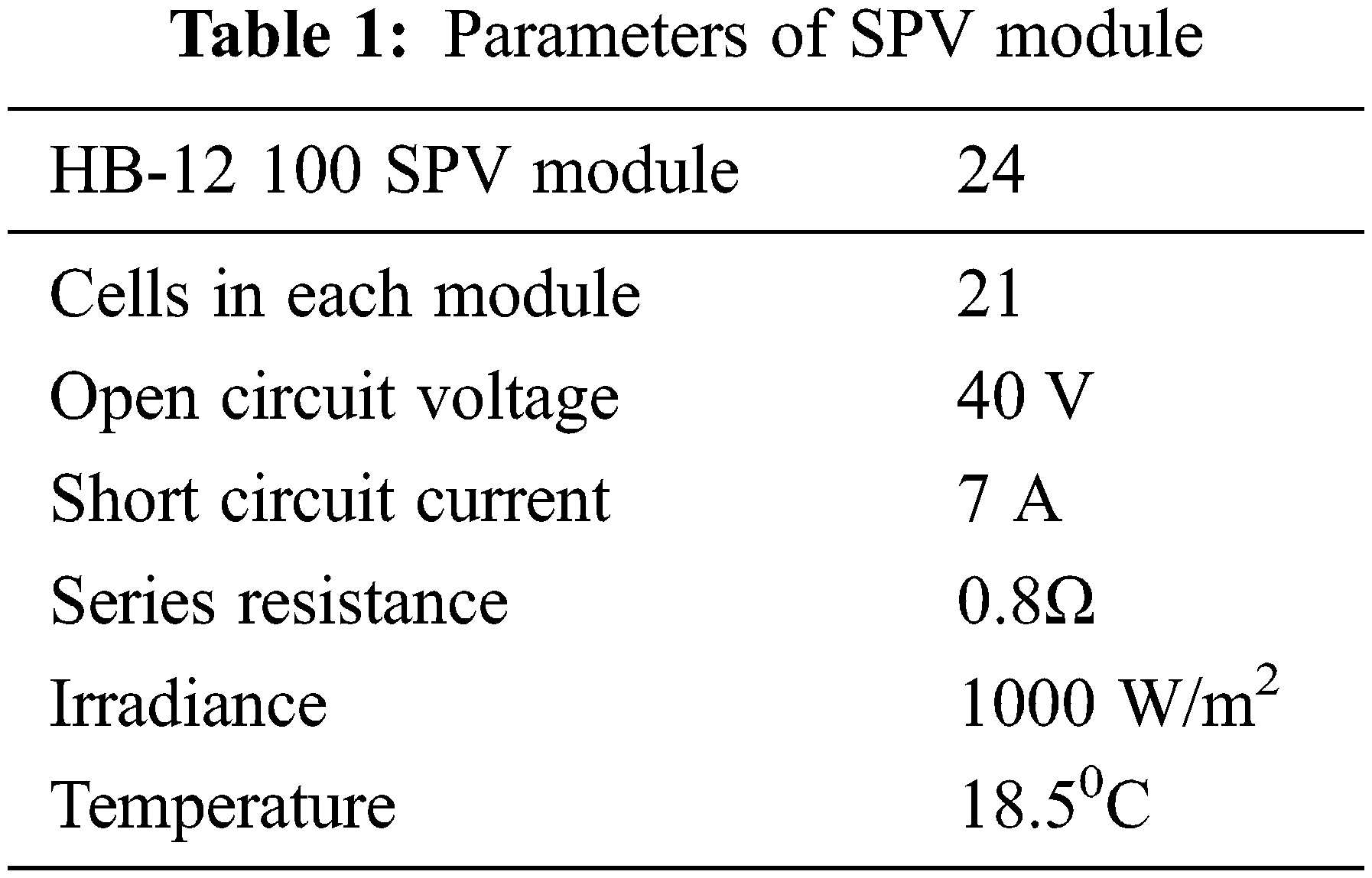
The MPP can be tracked effectively using the proposed CFF algorithm even under irregular variation in level of solar irradiance. Hence, output from the SPV is given to the load through the Luo converter after tracking the MPP using CFF. The parameters of SPV module is presented in Tab. 1.
3.2 Representation of Wind Energy System
Wind is the highest emergent renewable energy source, generally used for the production of power. The wind energy system make in use of the wind turbine that is coupled to a generator. Thus, the mechanical energy of the wind runs the turbine that drives the generator to generate the electrical energy. The power of wind turbine varies with the speeds of wind as the turbine speed varies with the wind speed. The power P produced with a blade of diameter d at a wind speed of S is expressed as,
where, ρ represents the density of air, s indicates the velocity of wind, and CP is the power coefficient. According to Betz's law, the maximum theoretical measure of CP is 0.593. In this paper, the MPP is tracked using the MPPT controller in the presence of the proposed CFF algorithm.
3.3 Proposed CFF Algorithm in Maximum Power Point Tracking
The proposed optimization strategy termed as CFF is developed with the hybridization of the algorithms, namely CSA [23] and FFA [24]. This algorithm is used in tracking the MPP of both solar and wind power plants. Both the branches of power generation can be controlled independently, in such a way to achieve the MPPT in a simultaneous manner. This hybrid system not only straps up increased energy, but also agrees to complement each other between day and night to certain extent.
The proposed CFF algorithm balances the advantages and the disadvantages of both the optimization algorithms. The CSA works on the basis of the life of a bird known as ‘cuckoo’, and the fundamental of this algorithm is the precise egg laying and breeding characteristics of cuckoo bird. CS generally involve in solving scheduling problems and design optimization problems in structural engineering. In involves in the global optimization of problems in case of different applications in electrical field.
FA is selected as it is a modern type swarm intelligence technique that involve in solving very tedious problems of optimization. FA is motivated due to the flash light characteristics of fire flies that identify a set of solution in random manner. The lower level of this algorithm, generally tries in the production of new solutions available in the space of search to produce the better outcome, whereas randomization involves in searching to overcome the solutions that are identified as local optimum. The solution is enhanced with the local search until finding enhancements. The meta-heuristic algorithms generally rely on the ability to balance between the two major phases, namely exploration and exploitation [25].
3.3.1 Algorithmic Procedure of CFF
The algorithmic procedure of CFF is stated as below,
Initialization of population: The population of fireflies is initialized in the first step. Assume that Xi is the number of fireflies, with i = 1, 2, …, n, where n represents the total fireflies.
Determination of light intensity and light absorption coefficient: The FFA depends mainly on two key things. One is the alteration of intensity of light and the other is the generation of attractiveness. Light intensity reduces with respect to the decrease in distance from that of the source and the light is also immersed by air. Hence, attractiveness must be permitted to change with the varying rate of absorption. The expression for light intensity L is given as,
The light absorption coefficient γ is considered as the primary value of L and is evaluated as,
where,
Position update using modified expression: The proposed algorithm that involves the hybridization of FFA and CS is formulated in this step. The progress of ith firefly is fascinated by the firefly j and the typical expression of FFA depending on this strategy is specified as,
where,
where, δ is the attractiveness, δ0 is the attractiveness with lij = 0.The notation lij is the space between two fireflies, and is represented as,
The standard expression of FFA is modified using the CS in such a way to improve the system operation as the characteristics of cuckoos are useful in evaluating the solution to optimization problems.
The standard equation of CS is given as,
where,
Substitute Eq. (12) in Eq. (8),
Thus, using Eq. (13), the locality of the fireflies is updated using the locality of fireflies in earlier iterations, attractiveness, space among two fireflies, and the light absorption coefficient.
Evaluation of fitness for best outcome: The measure of fitness is found with Eqs. (15) and (16) to evaluate the optimal values of power.
Stopping condition: Repeat from steps (ii) to (iv) till the completion of the maximum iterations. The flowchart of CFF is depicted in Fig. 3.

Figure 3: Flowchart of proposed CFF algorithm
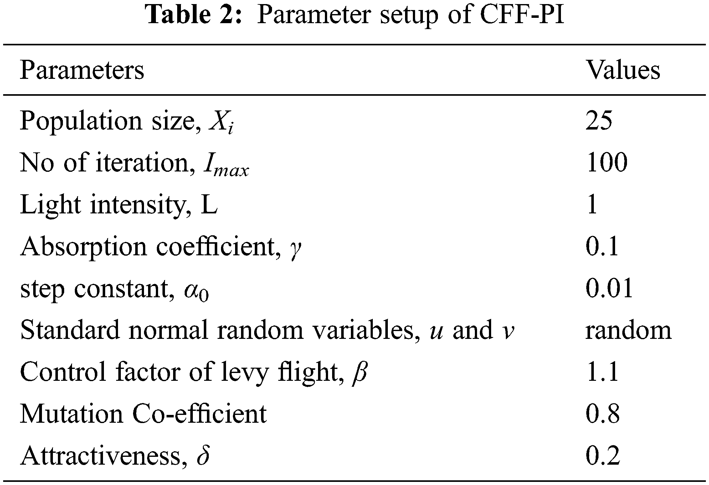
The CFF algorithm is effective in tracking the MPP of hybrid arrangement. The transient response characteristics of wind power system in the presence of CFF in MPPT enhance the system operation. In the same way, the CFF is effective in tracking the MPPT of solar array in an accurate and quick manner accurately. The output power produced from the MPPT controller is compared with the actual power output using a comparator, and the mismatch thus obtained is supplied to the controller. The parameter setting of CFF-PI algorithm is tabulated in Tab. 2.
The error generated is supplied to the PI controller, which is a control loop feedback strategy utilized for the rectification of error on the basis of both reference power and the measured power. It works in the basis that, when the voltage is a controlled variable, it is evaluated and given back to the controller. The Proportional gain kp generates the output that is directly proportional to the present error measure. The system becomes unstable with the higher value of kp. To maintain a stable system, the integral action must be introduced. The governing equation of the PI controller is expressed as,
where, PIt is the output response, e(t) indicates voltage error, t represents time period, Ts indicates sampling time, kp indicates the proportional gain, and ki represents the integral gain.
3.4 Operating Modes of Luo Converter
The Luo converter otherwise called as Positive output Luo converter (POLC) is a circuit, which can carry out both step-down and step-up process. The circuit model of POLC is indicated in Fig. 4. The switch used in this converter is run using a PWM based switching signal in the presence of repeating frequency f and duty cycle u.

Figure 4: Equivalent circuit of Luo converter
Mode I: During the ON state of switch S, L1 is charged with the input voltage E and diode D is inverse biased. Meanwhile, energy is absorbed by L2 from the source and C1. The capacitor C2 supplies the load. The equivalent circuit of mode I is depicted in Fig. 5a.
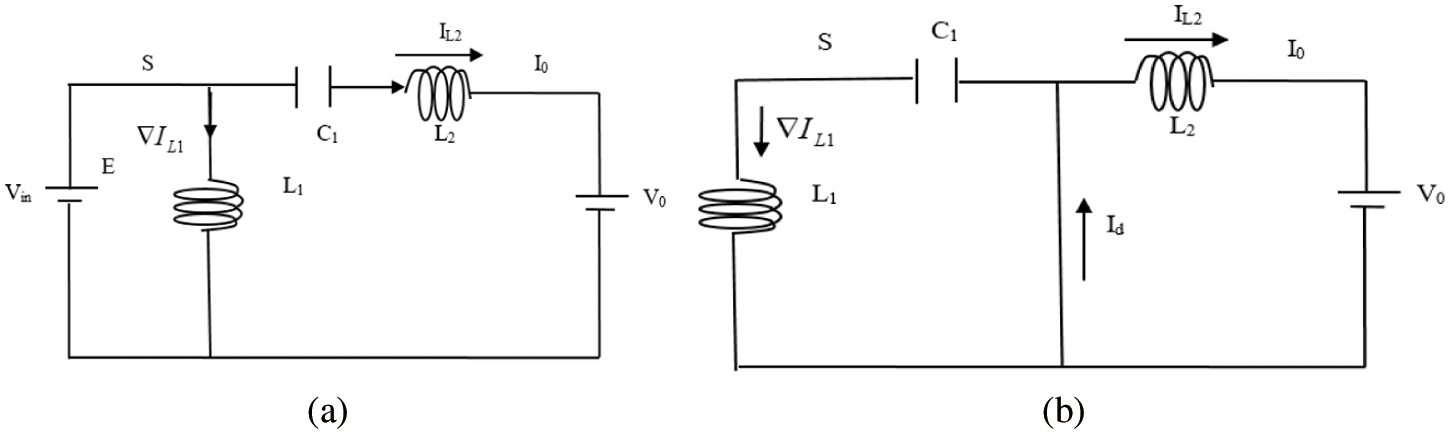
Figure 5: (a) Mode 1 operation of Luo converter, (b) Mode 2 operation of Luo converter
Mode II: When the switch S is in OFF condition, the current absorbed from the source become zero and the currents of inductors L1 and L2 passes through D and the equivalent circuit is depicted in Fig. 5b. Current IL1 passes through D to charge C1 , whereas current IL2 passes through the capacitor C2, resistor R and the freewheeling diode D to maintain as incessant [26].
Study of Luo Converter
The current IL2 across the inductor is expressed as,
The duty cycle of Luo converter is expressed as,
The output voltage equation of Luo converter circuit is specified as,
The voltage across C1 in an average is expressed as,
Peak to peak inductor current across the inductor L1 is given as,
The value of inductor L1 using the above expression is given as,
Current across the inductor L2 is expressed as,
The rate of inductor L1 using the above expression is given as,
The charge across C1 raises at off time by IL2 and reduces on time by IL1. The variation in charge on C1 should be nil [27–29].
The ripple voltage in capacitor C1 is specified as,
Value of capacitor C1 from the above expression is given as,
The ripple voltage in capacitor C2 is expressed as,
The rate of capacitor C2 from the expression given above is given as,
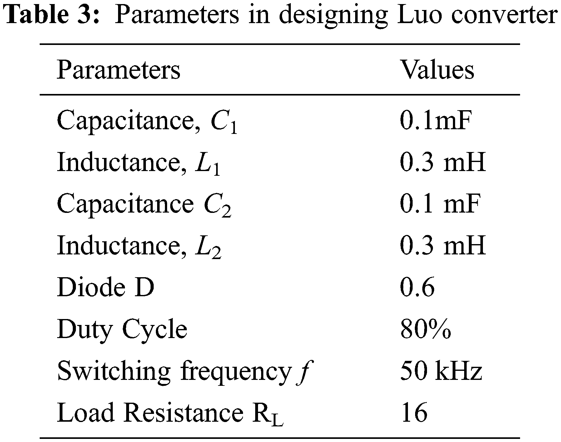
The parameters of the Luo converter with their ratings are tabularized in Tab. 3.
Simulation of wind/solar hybrid power system fed Luo converter based MPPT optimization connected to a load is done in Simulink environment of MATLAB as given in Fig. 6.
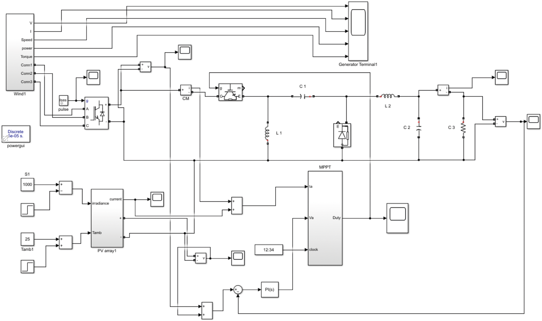
Figure 6: Simulink model of proposed system
A hybrid energy source is fed to the load through the Luo converter. Due to hybrid energy source, the parameters of the system vary that leads to the production of harmonics. Hence, to overcome this limitation, Luo converter is connected between the load and the source. The efficiency of Luo converter in the presence of PI controller, and the optimized gain parameters of PI controller by HAS, CS, FF and CFF method are presented in the simulation results.
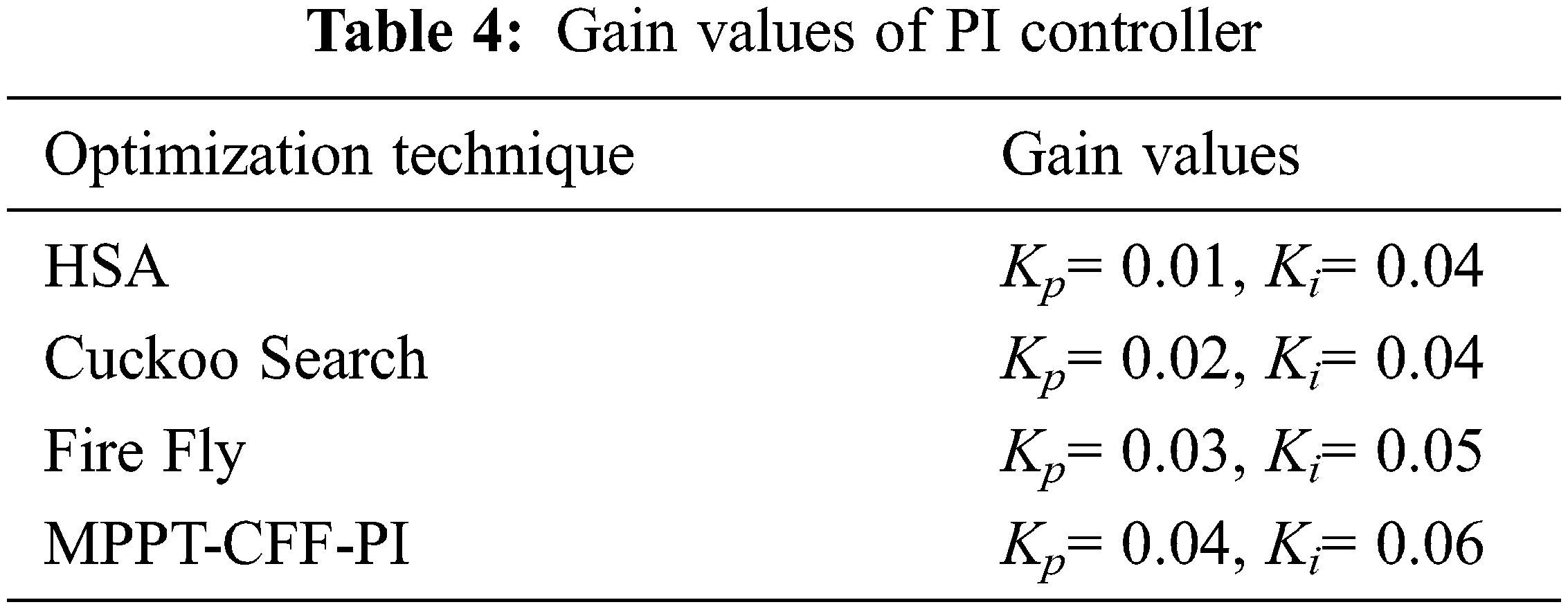
The effectiveness of MPPT-CFF-PI technique is analyzed under a variety of states, such as HAS-MPPT with PI, CS-MPPT with PI, FF-MPPT with PI and CFF-MPPT with PI. Tab. 4 shows the Optimal tuning gain parameters of algorithm.
4.1 System Performance Using HSA-MPPT with PI Controller
In this technique, the existing PI control is combined with HSA method to obtain the optimized gain values. Hence, it forms a MPPT-PI-HSA control technique to lessen the harmonics in the system. Figs. 7a and 7b deliberate the simulation results with MPPT-PI-HSA controlled Luo converter. The efficiency of the system with MPPT-PI-HSA controlled Luo converter is 97.8%. With MPPT-PI-HSA controller based Luo converter, the load voltage is improved to 300 V and the harmonics of the system is reduced, which indicates the efficiency of the MPPT-PI-HSA control system.
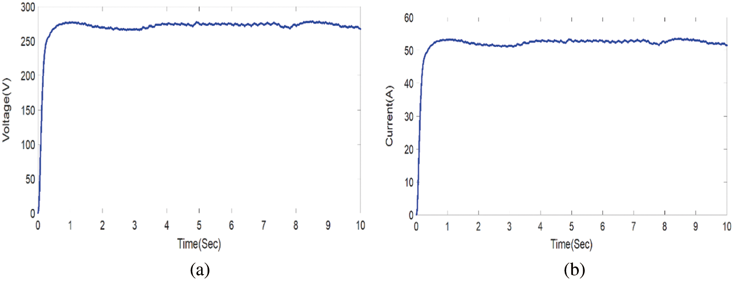
Figure 7: (a) Voltage response with MPPT-PI-HAS (b) Current response with MPPT-PI-HSA
4.2 System Performance Using CS-MPPT with PI Controller
In this technique, the existing PI control is combined with CS method to obtain the optimized gain values. Hence, it forms a MPPT-PI-CS control technique to lessen the harmonics in the system compared to MPPT-PI-HSA. Figs. 8a and 8b deliberates the simulation results with MPPT-PI-CS controlled Luo converter. The efficiency of the system with MPPT-PI-CS controlled Luo converter is 98.2%. With MPPT-PI-CS controller based Luo converter, the load voltage is improved to 300 V and the harmonics of the system is reduced compared to HSA based MPPT techniques, which indicates the efficiency of the MPPT-PI-CS control system.
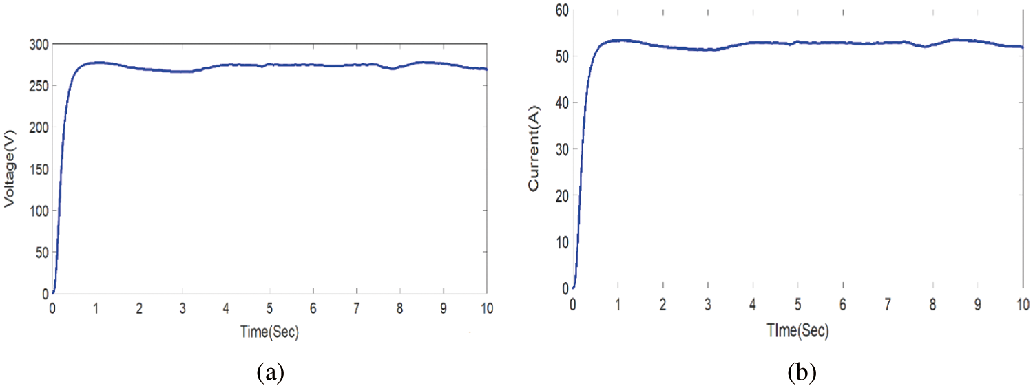
Figure 8: (a) Voltage response with MPPT-PI-CS (b) Current response with MPPT-PI-CS
4.3 System Performance Using FF-MPPT with PI Controller
In this technique, the existing PI control is combined with FF method to obtain the optimized gain values. Hence, it forms a MPPT-PI-FF control technique to lessen the harmonics in the system compared to MPPT-PI-HAS and MPPT-PI-CS. Figs. 9a and 9b deliberates the simulation results with MPPT-PI-FF controlled Luo converter. The efficiency of the system with MPPT-PI-FF controlled Luo converter is 98.9%. With MPPT-PI-FF controller based Luo converter, the load voltage is improved to 300 V and the harmonics of the system is reduced compared to HSA based MPPT technique and CS based MPPT technique, which indicates the efficiency of the MPPT-PI-FF control system.
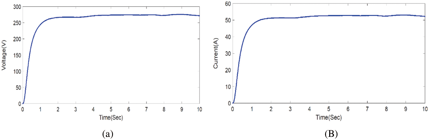
Figure 9: (a) Voltage response with MPPT-PI-FF (b) Current response with MPPT-PI-FF
4.4 System Performance Using CFF-MPPT with PI Controller
In this technique, the existing PI control is combined with CFF method to obtain the optimized gain values. Hence, it forms a MPPT-PI-CFF control technique to lessen the harmonics in the system compared to MPPT-PI-HAS, MPPT-PI-CS and MPPT-PI-FF. Figs. 10a and 10b deliberates the simulation results with MPPT-PI-CFF controlled Luo converter. The efficiency of the system with MPPT-PI-CFF controlled Luo converter is 99.2%. With MPPT-PI-CFF controller based Luo converter, the load voltage is improved to 300 V and the harmonics of the system is reduced compared to HSA based MPPT technique, CS based MPPT technique and FF based MPPT technique, which indicates the efficiency of the MPPT-PI-CFF control system.
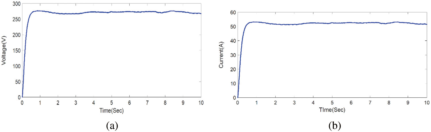
Figure 10: (a) Voltage response with MPPT-PI-FF (b) Current response with MPPT-PI-CFF
Due to the consequences of hybrid system, the converter output is overstated, and hence the precision of the waveform may get affected. Fig. 11 shows that the power is enhanced when the MPPT-PI-CFF controlled Luo converter is in operation.
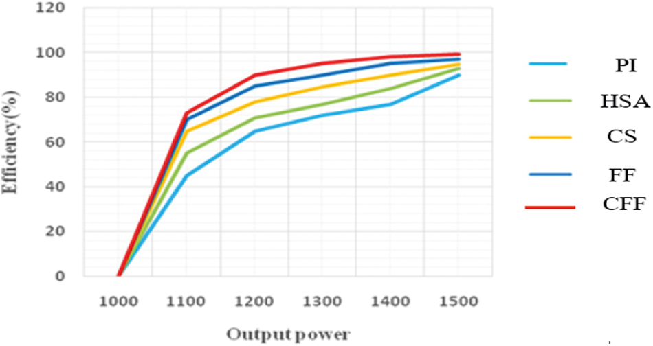
Figure 11: Comparison of efficiency
The comparative chart on terms of efficiency is depicted in Fig. 11. In Tab. 5, efficiency among various optimization techniques is compared and tabulated. The proposed technique demonstrates an increased efficiency of about 99.2%.
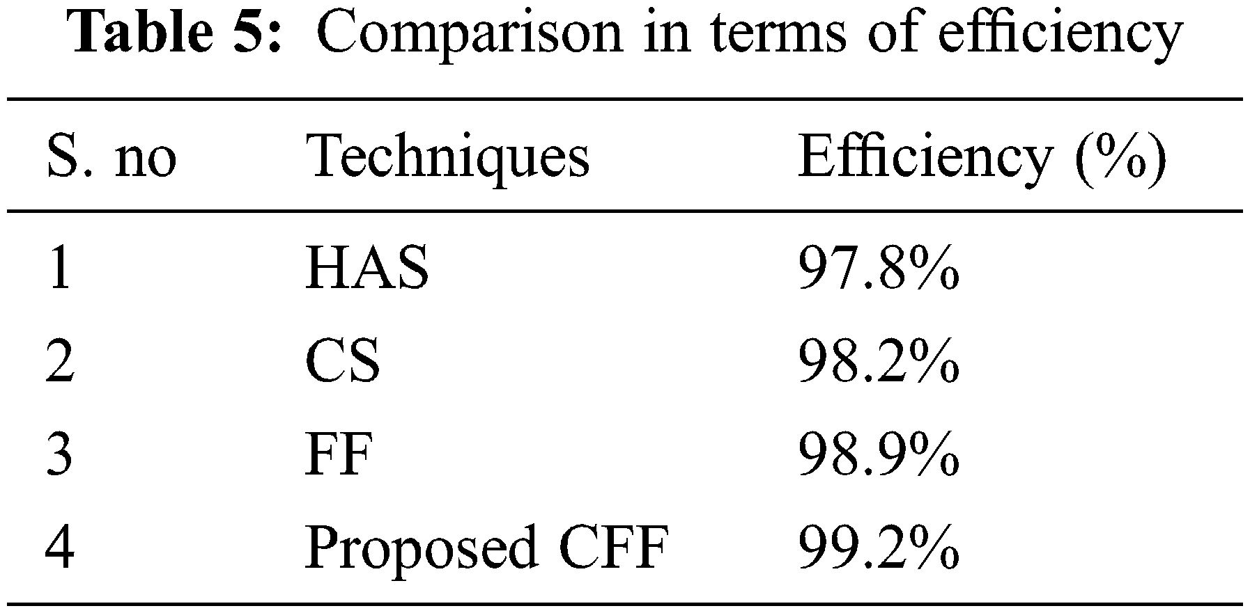
Fig. 11 deliberates the assessment of proposed technique in terms of efficiency with existing algorithms and the proposed MPPT-PI-CFF controlled Luo converter technique shows a higher efficiency. The proposed MPPT-PI-CFF controlled Luo converter has the good output voltage, current, power value as given in Tab. 6, when compared to existing methods, such as HSA, CS, and FF.

From Fig. 12 it is clear that the MPPT-PI-CFF controlled Luo converter has better efficiency in terms of duty cycle. The MPPT-PI-CFF controlled Luo converter has an efficiency of 99.2%, which is 10% better than the P&O, Fuzzy and I.C.

Figure 12: Efficiency comparison with duty cycle
This paper introduces a newly developed MPPT algorithm called Cuckoo-Firefly (CFF) for standalone wind-solar hybrid system. Due to the varying characteristics of solar and wind sources, it is important to find out the optimal voltage that guarantee the acquiescent of maximum power from both wind-solar hybrid power generation systems. The CFF algorithm is the hybridization of CS and the FF. The proposed model comprises of a Proportional Integral controller (PI) controlled LUO converter that involve in controlling the power given to the load. The Proposed technique produces 99.2% efficiency. Fore future this work is compared with various other novel optimization techniques to improve the efficiency.
Acknowledgement: The author with a deep sense of gratitude would thank the supervisor for his guidance and constant support rendered during this research.
Funding Statement: The authors received no specific funding for this study.
Conflicts of Interest: The authors declare that they have no conflicts of interest to report regarding the present study.
Reference
1. K. Hari, K. Ashokkumar and S. Bharathkumar, “A nonlinear controller for photovoltaic water pumping system,” International Journal of Engineering Trends and Technology, vol. 4, no. 5, pp. 2212–2216, 2013. [Google Scholar]
2. C. I. Hoarcă and F. M. Enescu, “On the energy efficiency of standalone fuel cell/renewable hybrid power sources part i: simulation results for constant load profile without RES power,” in Proc. Int. Conf. on Applied and Theoretical Electricity (ICATE), Craiova, Romania, pp. 1–6, 2018. [Google Scholar]
3. H. Suryoatmojo, T. Hiyama, A. A. Elbaset and M. Ashari. “Optimal design of wind-PV-diesel-battery system with GA,” IEEJ Transactions on Energy and Power, vol. 129, no. 3, pp. 413–420, 2009. [Google Scholar]
4. Y. Jiang, J. A. A. Qahouq and M. Orabi, “AC PV Solar System distributed architecture with maximum power point tracking,” in Proc. Int. Conf. on Telecommunications Energy, Scottsdale, AZ, USA, pp. 1–5, 2012. [Google Scholar]
5. A. Sharma, H. P. Singh and S. K. Sinha, “Performance enhancement of integrated solar-wind hybrid energy system using MPPT,” in Proc. Int. Innovative Applications of Computational Intelligence on Power, Energy and Controls with Their Impact on Humanity (CIPECH), IEEE, Ghaziabad, India, pp. 1–4, 2018. [Google Scholar]
6. G. Anandhakumar, M. Venkateshkumar and P. Shankar, “Fuzzy logic controller based MPPT method for the photovoltaic power system,” Artificial Intelligent Systems and Machine Learning, vol. 5, no. 12, pp. 477–481, 2013. [Google Scholar]
7. N. Ali, R. Jayabharath and M. D. Udayakumar, “An ANFIS based advanced MPPT control of a wind-solar hybrid power generation system,” International Review on Modelling and Simulations,” vol. 7, no. 4, pp. 638, 2014. [Google Scholar]
8. A. Thiyagarajan, S. P. Kumar and A. Nandini, “Analysis and comparison of conventional and interleaved DC/DC boost converter,” in Proc. Int. Conf. on Current Trends in Engineering and Technology-ICCTET 2014, Coimbatore, India, pp. 198–205, 2014. [Google Scholar]
9. F. L. Luo and H. Ye, “Advanced dc/dc converters,” in Engineering & Technology, 2nd Edition, Boca Raton: CRC Press, pp. 774, 2016. [Google Scholar]
10. A. Kavitha and G. Uma, “Analysis of hopf bifurcation in DC-DC luo converter using continuous time model,” in Proc. Int. Conf. on Power Electronics and Drive Systems, Bangkok, Thailand, pp. 386–390, 2007. [Google Scholar]
11. B. Achiammal and R. Kayalvizhi, “Genetic algorithm based PI controller for negative output elementary LUO converter,” in Proc. Int. Conf. on Advanced Communications, Control and Computing Technologies, IEEE, Ramanathapuram, India, pp. 1099–1103, 2014. [Google Scholar]
12. J. Gnanavadivel, P. Yogalakshmi, N. S. Kumar and K. K. Veni, “Design and development of single phase AC–DC discontinuous conduction mode modified bridgeless positive output Luo converter for power quality improvement,” IET Power Electronics, vol. 12, no. 11, pp. 2722–2730, 2019. [Google Scholar]
13. K. Kumar and K. R. Prabhu, “Design of RBFN-based single MPPT for hybrid solar and wind energy system,” IEEE Access, vol. 5, pp. 15308–15317, 2017. [Google Scholar]
14. W. M. Lin, C. M. Hong and C. H. Chen, “Neural-network-based MPPT control of a stand-alone hybrid power generation system,” IEEE Transactions on Power Electronics, vol. 26, no. 12, pp. 3571–3581, 2011. [Google Scholar]
15. S. K. Tiwari, B. Singh and P. K. Goel, “Design and control of autonomous wind–Solar System with DFIG feeding 3-phase 4-wire loads,” IEEE Transactions on Industry Applications, vol. 54, no. 2, pp. 1119–1127, 2017. [Google Scholar]
16. C. Liu, K. T. Chau and X. Zhang, “An efficient wind–photovoltaic hybrid generation system using doubly excited permanent-magnet brushless machine,” IEEE Transactions on Industrial Electronics, vol. 57, no. 3, pp. 831–839, 2009. [Google Scholar]
17. K. Kumar, R. Tiwari, N. R. Babu and K. R. Prabhu, “Analysis of MISO super lift negative output luo converter with MPPT for DC grid connected hybrid PV/wind system,” Energy Procedia, vol. 145, pp. 345–350, 2018. [Google Scholar]
18. H. Fathabadi, “Novel high-efficient large-scale stand-alone solar/wind hybrid power source equipped with battery bank used as storage device,” Journal of Energy Storage, vol. 17, pp. 485–495, 2018. [Google Scholar]
19. C. M. Hong, T. C. Ou and K. H. Lu, “Development of intelligent MPPT (maximum power point tracking) control for a grid-connected hybrid power generation system,” Energy, vol. 50, pp. 270–279, 2013. [Google Scholar]
20. S. Saravanan and N. R. Babu, “RBFN based MPPT algorithm for PV system with high step up converter,” Energy Conversion and Management, vol. 122, pp. 239–251, 2016. [Google Scholar]
21. F. Z. Kadda, S. Zouggar, M. El Hafyani and A. Rabhi, “Contribution to the optimization of the electrical energy production from a hybrid renewable energy system,” in Proc. Int. Renewable Energy Congress (IREC), Hammamet, Tunisia, pp. 1–6, 2014. [Google Scholar]
22. P. Sharma, “Performance analysis of a stand-alone hybrid renewable energy power system-a simulation study,” in Proc. 2015 Annual IEEE India Conf. (INDICON), New Delhi, India, pp. 1–6, 2015. [Google Scholar]
23. C. Zefan and Y. Xiaodong, “Cuckoo search algorithm with deep search,” in Proc. Int. Conf. on Computer and Communications (ICCC), Chengdu, China, pp. 2241–2246, 2017. [Google Scholar]
24. X. S. Yang, “Firefly algorithms for multimodal optimization,” in Proc. Int. Symposium on Stochastic Algorithms, Springer, Berlin, Heidelberg, pp. 169–178, 2009. [Google Scholar]
25. S. Arora and S. Singh, “The firefly optimization algorithm: Convergence analysis and parameter selection,” International Journal of Computer Applications, vol. 69, no. 3, pp. 48–52, 2013. [Google Scholar]
26. N. R. Abjadi, M. Mahdavi and H. Akbari, “Emotional controller (BELBIC) for positive output Luo converter,” in Proc. Int. Conf. on Control, Instrumentation, and Automation (ICCIA), IEEE, Shiraz, Iran, pp. 206–211, 2017. [Google Scholar]
27. A. Manikandan and N. Vadivel, “Design and implementation of LUO converter for electric vehicle applications,” International Journal of Engineering Trends and Technology, vol. 4, no. 10, pp. 4437–4441, 2013. [Google Scholar]
28. D. Choudhary and A. R. Saxena, “Incremental conductance MPPT algorithm for PV system implemented using DC-DC buck and boost converter,” International Journal of Engineering Research and Applications, vol. 4, no. 8, pp. 123–132, 2014. [Google Scholar]
29. V. V. G. Pentapalli and R. K. Varma, “Cuckoo search optimization and its applications: A review,” International Journal of Advanced Research in Computer and Communication Engineering, vol. 5, no. 11, pp. 2319–5940, 2016. [Google Scholar]
 | This work is licensed under a Creative Commons Attribution 4.0 International License, which permits unrestricted use, distribution, and reproduction in any medium, provided the original work is properly cited. |