DOI:10.32604/iasc.2022.025217
| Intelligent Automation & Soft Computing DOI:10.32604/iasc.2022.025217 | |
| Article |
Adaptive Neuro-Fuzzy Based Load Frequency Control in Presence of Energy Storage Devices
Department of Electrical and Instrumentation Engineering, Thapar Institute of Engineering and Technology, Patiala, 147004, India
*Corresponding Author: Pankaj Jood. Email: pjood0000@gmail.com
Received: 16 November 2021; Accepted: 12 January 2022
Abstract: Energy storage technologies are utilized for improving the primary frequency control in complex electrical systems. In this paper, the modeling and simulation of a two-area power system is done to evaluate and compare the impact of three different energy storage applications on load frequency control performance. Capacitive energy storage (CES), battery energy storage (BES), and superconducting magnetic energy storage (SMES) are considered for the study. On the basis of peak overshoot and settling time, the performance of these energy storage devices is compared. The power system consists of thermal, wind, and solar resources. All nonlinearities are incorporated in the system model. Both conventional and artificial intelligence (AI) based controllers are tested for the case study. The simulations are carried out under multiple operating conditions and penetration levels of renewable sources. It is found that the primary frequency response of the test system is improved in the presence of the storage facilities and the neuro-fuzzy controller. The simulation results exhibit that the SMES displays the best performance indices. The prime contribution of the paper is to investigate and compare the response of the storage devices in a realistically modeled power system with renewable resources using both conventional and AI controllers.
Keywords: Artificial intelligence; energy storage; frequency response; renewable integration; system simulation
For reliable and secure operation of electrical systems, a fast and appropriate load frequency control (LFC) technique is desired [1]. The LFC matches the power generation with continuously varying consumption [2]. It consists of three control approaches, namely inertial response (IR), primary control, and secondary control based on the reaction time [3]. The IR is the fastest and inherently a part of the system inertia. It occurs due to the physical phenomenon of stored kinetic energy in the rotating parts of electric motors and synchronous generators. Whenever any real power unbalance occurs, the system’s immediate response is to release this energy to arrest the change in frequency. The primary and secondary controls are provided by the turbine governor and a supplementary controller, respectively [4].
The response of the system gets affected due to the rising penetration of renewable energy resources (RES) [5]. A high RES level results in lowering mechanical inertia since the RES are characterized by significant up or down ramps [6]. A low inertia power system suffers from the high rate of frequency change in case of real power mismatch [7].
Many technologies are available to meet the additional flexibility requirements in LFC, like installing fast-start gas turbines, providing control mechanisms such as flywheels, demand-side flexibility, and deploying energy storage system (ESS) [3,8]. Among these, the ESS is able to support the primary response effectively by storing and releasing the energy as per the requirements [9,10]. The ESS may also help in stand-alone peak load reduction and provide voltage support [11]. The storage systems are categorized as electrochemical, mechanical, electrical, and thermal storage depending on their conversion form, as shown in Fig. 1. The energy can be stored in the electrochemical form in battery energy storage (BES). In capacitive energy storage (CES) devices, it can be stored in electrostatic form [12]. On the other hand, the superconducting magnetic energy storage (SMES) stores the energy in the magnetic form [13].
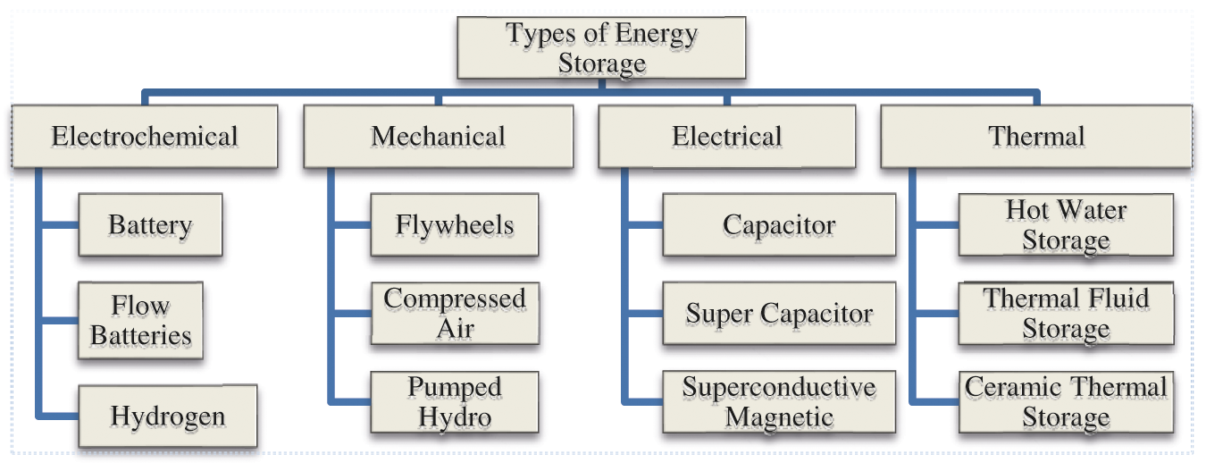
Figure 1: Categorization of energy storage system
The dynamic response of BES to sudden changes in the real power requirements has been observed faster than uncoordinated control [14]. While the BES is high-energy and low-power density storage media, the CES is just the opposite [15]. The CES is not suitable for large energy storage applications due to its low energy density and high dielectric losses in the capacitor. However, a low rating CES can be efficiently used for stabilizing the frequency [16]. The SMES is a self-commutated converter-based storage facility that has control over both real and reactive powers. It is suitable for frequency regulation due to its low discharge rate and fast action [17,18]. The discharge time of BES lasts several minutes, while CES and SMES have a discharge time of a few seconds only.
From control perspective, the fixed gain controllers such as the proportional-integral (PI) or proportional-integral-derivative (PID) have found usage for secondary control applications [3]. These controllers are suitable for nominal operating conditions, but their performance may be inadequate under sudden and large perturbations [19]. For optimal control, it is preferable to monitor the operational conditions and update the controller parameters. Therefore, variable structure and state feedback controllers have been developed for the frequency control applications [3]. However, these advanced controllers are sensitive to non-linear system dynamics and parametric variations.
The adaptive controllers designed for LFC applications exhibit self-adjusting gain settings, but these controllers require a perfect system model for their design [17]. The other type, robust controllers, also require extensive and precise mathematical modeling [20]. The aartificial intelligence (AI) based controllers have been reported that mitigate the effects of system uncertainties [21,22]. A fuzzy logic-based PI controller (FLC) has been developed to overcome system nonlinearities and parametric limitations [23]. The genetic algorithm (GA) based fuzzy gain scheduling technique has also been designed [24]. It has been observed that a non-linear type-2 FLC provides an improved control response [23,25]. In contrast to an FLC, learning is an essential ability of artificial neural network (ANN) controllers [26]. However, ANN controllers are flexible yet challenging to be trained effectively. As a result, adaptive network-based fuzzy inference system (ANFIS) controllers that leverage the strengths of both FLC and ANN have been developed [27].
In a two-area power system case study, the ANFIS controller outperformed the PI controller in steady-state performance [28]. An improved dynamic performance from the ANFIS controller has also been observed compared to ANN and FLC controllers in a three-area power system having thermal and hydro plants [29]. The LFC response in the presence of storage technologies has been examined in some papers. A two-area system with CES was analyzed but without the participation of renewable resources [15]. A two-area system has been studied using CES without any nonlinearity and RES involvement [16]. While simulating a two-area system with SMES, the authors noticed enhanced primary frequency response characteristics [17]. The authors observed significant improvement in frequency deviations in the presence of Redox Flow Batteries (RFB) and SMES [30]. However, in most of the papers, the nonlinearities of real-time power system have not been considered. In another study of ESS, only one non-linearity, governor dead band (GDB), has been included, but the RES participation has not been considered [8]. The benefits of different types of storage devices for the LFC problem in a micro-grid have also been explored [9]. It has been observed that the ANFIS exhibits a better transient response than the other controllers when accompanied by SMES units [31].
A review of the above literature pertaining to the LFC area shows that the ANFIS controllers have not been analyzed adequately when different storage devices are connected in the system [31]. Moreover, most of the ESS control applications using fuzzy controllers have been limited to only micro-grids [9–11,32]. The modeling of system nonlinearities, like generation rate constraint (GRC), GDB, boiler dynamics (BD), and communication delays (CD), has not been considered while simulating the response of storage devices [19,25,26]. Therefore, the main contribution and focus of this paper are to verify and compare the performance of the different storage devices, i.e., BES, CES, and SMES, using conventional and ANFIS controllers with complete modeling of system nonlinearities. In addition to this, the performance has been investigated in the presence of RES, which makes the mitigation of frequency deviations more challenging.
The paper is structured as follows: the modeling of two-area power systems, BES, CES, and SMES, is given in Section 2. The proposed ANFIS controller’s design process is presented in Section 3. The outcomes of the simulation are compared and analyzed in Section 4. The last section is the conclusion.
Technically, LFC minimizes an area control error (ACE) known as an index of frequency statistics. The schematic diagram of two area thermal power system is shown in Fig. 2. Here frequency deviation (Δf) is an error signal in each area, and tie-line power deviation (ΔPTie) is an error signal between two areas. Both Δf and ΔPTie are amplified, mixed and transformed into real power command signal to control the steam input through a valve control mechanism.
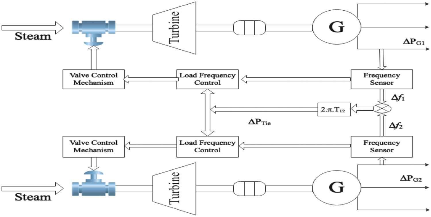
Figure 2: The schematic diagram of two area power system
The ACE consists of system frequency deviations and tie-line power exchanges in interconnected areas. It is computed in a control center after every few seconds (2 to 6 s), and new set points are communicated to the generators dedicated for automatic generation control (AGC). The tie-line bias control strategy has the following ACE Eqs. for the two areas [5,6]:
and
where j is the index for an area, ΔPTie is the distinction between the actual and standard interchange, Δf is the deviation between measured and scheduled frequency, Bf is the frequency bias setting, and Ki and KP are the integral and proportional gains of a PI controller, respectively. These gains are tuned to adjust the controller’s response in an area j. The ACE signal is formulated by the regulator and communicated to a supplementary controller. This controller then generates the control signal representing each generating unit’s contribution to the total generation.
The transfer function model of the power system is shown in Fig. 3. This system consists of thermal, wind, and solar energy resources. The integration of the fluctuating renewable generation units is done using time-series datasets having one-second resolution [6,19]. The proportion of these resources can be changed by selecting the installed capacity of that area. Various nonlinearities have been considered in the model, which includes GRC at 0.1 p.u. MW/min or 0.0017 p.u. MW/s, GDB (with 0.06% backlash), BD (3%/min), and CD of about 2 s [19]. The tie-line is modeled using a multiplying factor 2πT12 and an integrator. T12 is the synchronizing torque coefficient. The power deviations in the two areas, ΔPL1 and ΔPL2 are the two inputs. The load generation relationship in the two areas is represented by Eqs. (4) and (5) as follows:
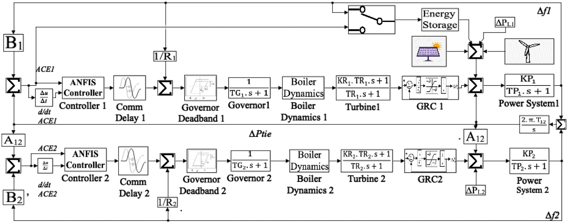
Figure 3: A two-area power system that incorporates renewable resources and storage units
A detailed explanation of these symbols is given in the previous study [19].
The ESS has been integrated using a transfer function approach. The ESS can be sourced with two different signals, i.e., Δf and ACE. Here, Δf is a slight change in frequency concerning the reference frequency. Each ACE term incorporates a frequency biasing factor (B) that constitutes the frequency-sensitive component of the load (D) and governor speed droop (R).
The parameter B increases with an increase in system load and vice-versa. Δf is affected by system loading. Since ACE is a function of Δf, either ACE or Δf can be chosen for feeding the ESS through a selector switch. In the proposed model, ESS of AREA 1 is fed by the frequency deviation signal (Δf1).
2.2 Modeling of Energy Storage Systems (ESS)
The modeling of various ESS devices is discussed in this sub-section. An overview of the parameters related to the ESS units has been provided [12,15].
2.2.1 Capacitor Energy Storage (CES)
The supercapacitors utilize two oppositely charged metal plates separated by a dielectric material to store electrostatic field energy [33]. The energy (EN) stored in an ideal capacitor of capacitance C at voltage E is given in Eq. (7) [34]:
The energy increases as the square of the applied voltage (E). This voltage is constrained by the breakdown strength of the dielectric material. When charged at a constant current (I), the voltage (E) of an ideal capacitor rises linearly with time. When charged at constant power (P), the energy (EN) rises linearly with time. In order to prevent discontinuous control during disturbances, the capacitor voltage Ed is maintained within lower and upper limits given in Eqs. (8)–(11).
The limits can be considered as:
After a disturbance, Edmust quickly return to its initial value Ed0. The time frame to return to its initial value depends upon the energy supplied or absorbed by the CES unit. In this work, a storage capacity of 38 MJ has been considered, capable of supplying MWh for a few seconds. After the initial power disturbance, the CES unit is ready to work for subsequent interferences.
The model of the CES system is made up of a series of combinations of an inductor, a resistor, and a capacitor, as in Fig. 4. This circuit can be represented as a first-order transfer function [15,16]. The Δf is used as an input signal to lower the steady-state error and control the power output. The CES control loop utilizes voltage deviation of the capacitor (ΔEd) as negative feedback [34]. The deviated voltage and current of the capacitor are given in Eqs. (12) and (13). ΔPCES is the power released by the CES during load changes.
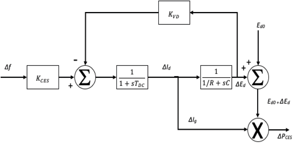
Figure 4: CES block diagram in MATLAB SIMULINK
The variations in ΔEd, ΔId and ΔPCES during sudden fall in load demand are shown in Fig. 5. A sudden load drop will lead to a positive change in Δf. It can be observed that the response of all the signals is continuous. The capacitor voltage starts rising exponentially towards its final value to absorb the surplus energy of the system. As load demand stabilizes, the capacitor voltage attains its final value. The opposite response is observed for an unexpected increase in load demand.
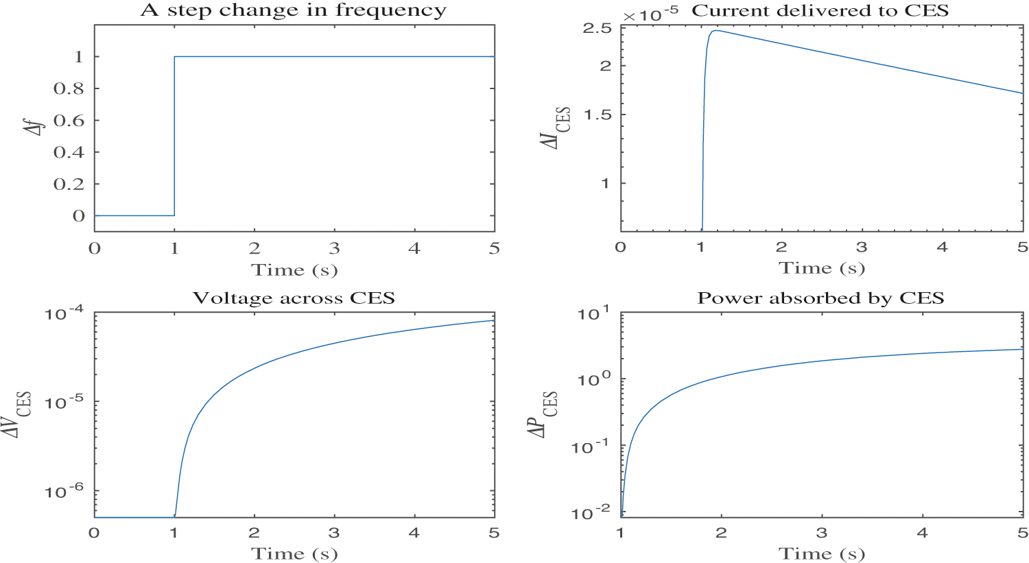
Figure 5: Response of CES to a unit disturbance
2.2.2 Battery Energy Storage (BES)
A battery in combination with a fast-reacting inverter can provide a fast-active control in the form of high short circuit power. The response time is between 0.5 and 1 s [11,14]. The representation of BES is shown in Fig. 6 [35,36]. There are two inputs (Δf and Et) and one output (ΔPBES) in this model. ΔIbes is the actual current generated in the circuit (Eq. (15)) and I0bes is the reference value for Ibes.
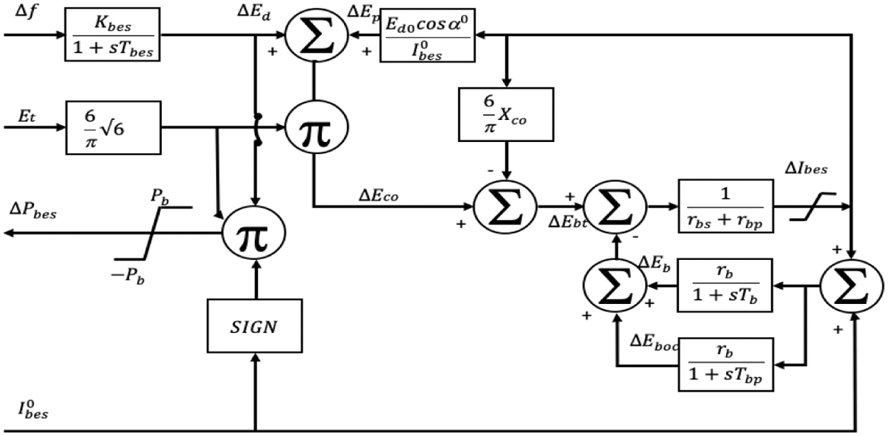
Figure 6: BES block diagram in MATLAB SIMULINK
The equivalent battery’s open terminal voltage is calculated in Eq. (16):
Active power (Pbes) and reactive power (Qbes) are given in Eqs. (17) and (18):
For active source P-modulation,
Since, Qbes is zero, the BES is a source of active power only which helps in absorbing the dynamic power deviations. The response of BES to a significant shift in the Δf signal is shown in Fig. 7. It is clear that as compared to the reaction of CES, the BES offers faster response.
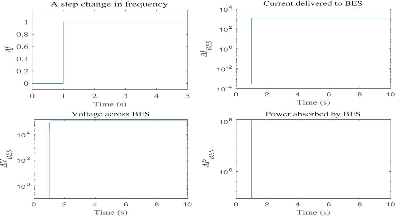
Figure 7: Response of BES to a unit disturbance
2.2.3 Superconducting Magnetic Energy Storage (SMES)
The SMES system is made up of a superconducting coil, a power conditioning system (PCS), and a refrigerator [17]. Energy is stored in the coil in the form of a magnetic field, and the coil temperature is maintained below its superconducting critical temperature (−200°C to −300°C) [25,26]. The PCS consists of an inverter and a rectifier unit, and its purpose is to provide a direct current source to the coil. Once the coil is charged, its current does not decay, and the coil can hold the magnetic energy for an extremely long time-period. Whenever required, the coil can discharge its energy to the network. In each direction of power flow, there is a loss of 2%–3% of energy in the PCS.
With the help of a self-commutated converter, the SMES controls both the active and reactive power simultaneously. The SMES model in this work has a storage capacity of 38 MJ that is capable of supplying MWh for a few seconds. Similar to CES and BES, the error signal, i.e., Δf is fed to the SMES to reduce steady-state error and to adjust the power of SMES as depicted in Fig. 8. Due to the governor control action, the power system is settled for a new equilibrium point. During this period, the energy of the SMES coil returns to its nominal value. Eqs. (21)–(23) are the equations of voltage and current deviation of the SMES.
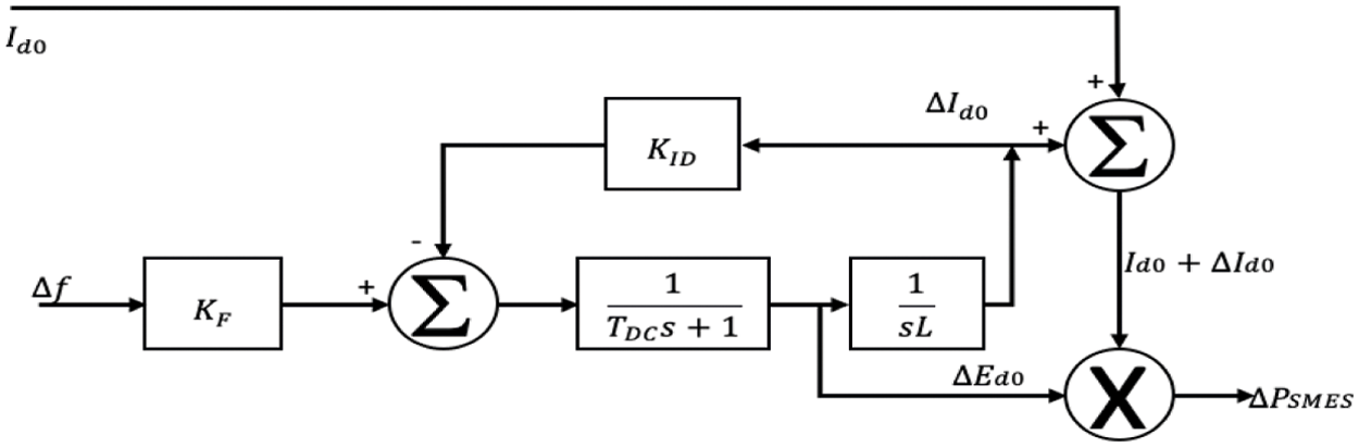
Figure 8: SMES block diagram in MATLAB SIMULINK
Thus, the power delivered by the SMES unit is:
The current deviation in the coil is fed back in the SMES control loop to obtain fast recovery of both current and energy levels. The response of SMES to a significant shift in the Δf signal is depicted in Fig. 9. During a sudden fall in system load demand, the voltage change happens at a breakneck speed while the build-up in current and power occurs exponentially.
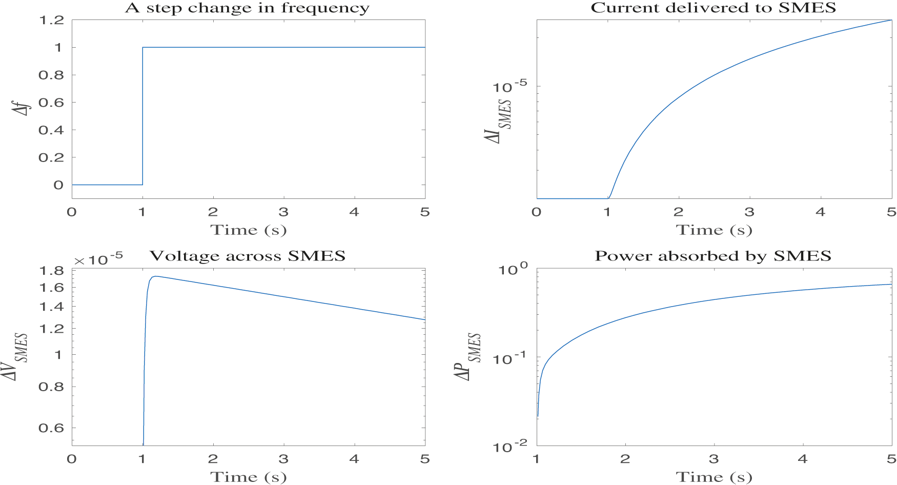
Figure 9: Response of SMES to a unit disturbance
3 Description of ANFIS Controller
The primary function of the ANFIS controller is to produce a control signal that keeps system frequency and tie-line interchange power within permissible limits [37,38]. The control signal is generated based on the two inputs: (i) frequency error (ACE(t)) and (ii) change in frequency error (ΔACE(t)). The flowchart for designing the ANFIS controller is shown in Fig. 10.
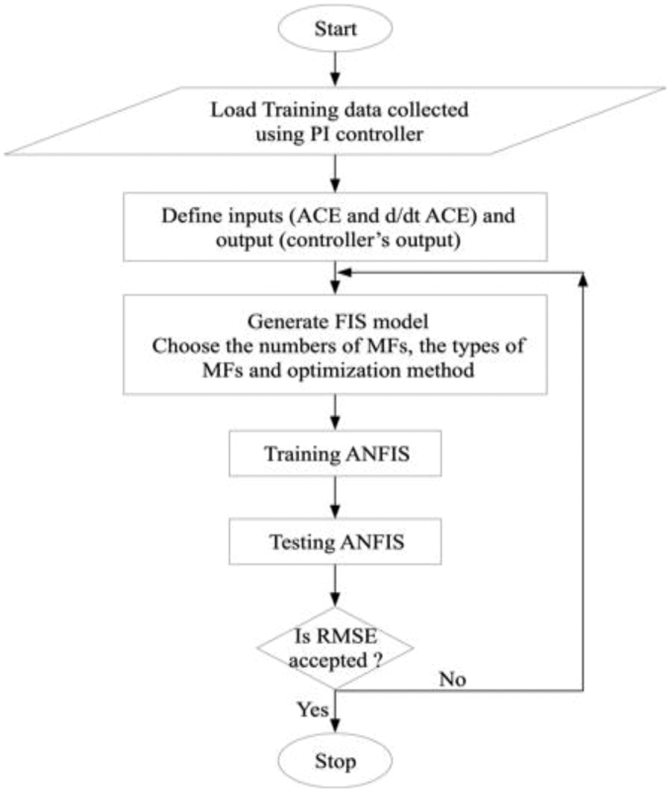
Figure 10: Flowchart for ANFIS design
Each input and output signal has been fuzzified using three gaussian membership functions (MF). The MF parameters are computed or adjusted based on a gradient vector. Takagi sugeno kang (TSK) type fuzzy inference system (FIS) has been used to model the input-output data for a given set of MF parameters. Once the gradient vector is calculated, a hybrid of least squares estimation (LSE) and back-propagation (BP) algorithm are applied to assess the weights. The root mean square error (RMSE) has been considered as the error criterion. The following steps are adopted for training the ANFIS controller [38,39]:
a) Draw the model of the two-area power system using a PI controller.
b) Generate the training data consisting of inputs and output pairs using an optimally tuned PI controller. The Bode plot technique is applied for tuning the PI controller [19]. The PI controller parameters (Kp and Ki) have been adjusted for a minimum phase and gain margins of 76° and 0.85, respectively. In these settings, the performance of the system remains stable for minor disturbances [17]. The training data must be reflective of the plant’s behavior for different dynamic conditions. Therefore, the test system has been subjected to step load alterations varying from 0.005 to 0.04 p.u. To generate a diversified dataset, each wind and solar generation level has been varied from 3% to 6%. The ANFIS parameters for training are given in Tab. 1.
c) Use “anfisedit” to create the .fis file.
d) Load the training data in the model and create the FIS structure.
e) The generated FIS has been trained for a fixed number of epochs. As displayed in Fig. 11, after ten epochs, the network gets completely trained. The control surface of ANFIS after training, is shown in Fig. 12.
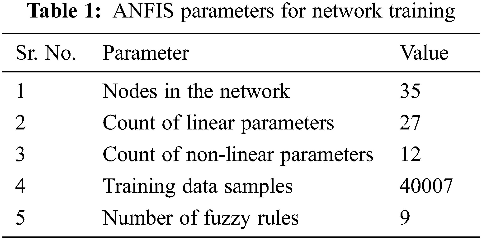

Figure 11: Convergence of training error
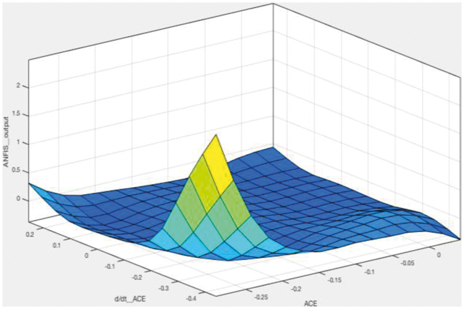
Figure 12: Control surface of ANFIS
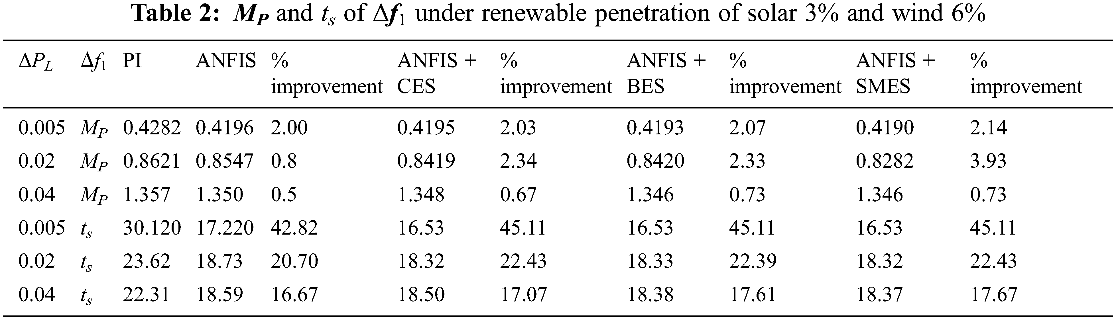
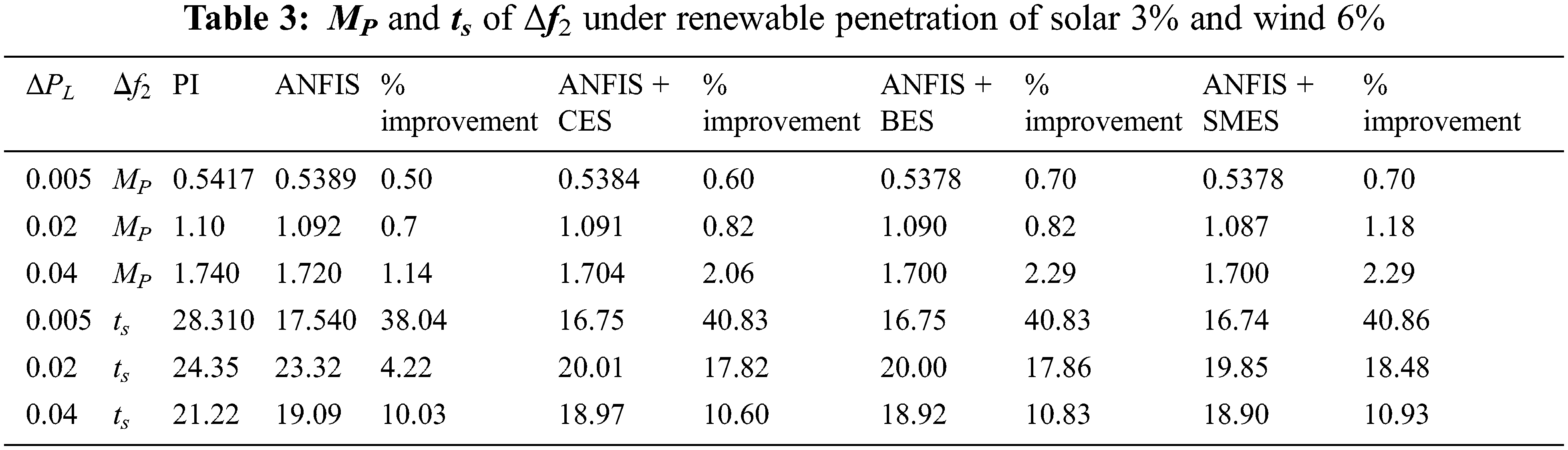
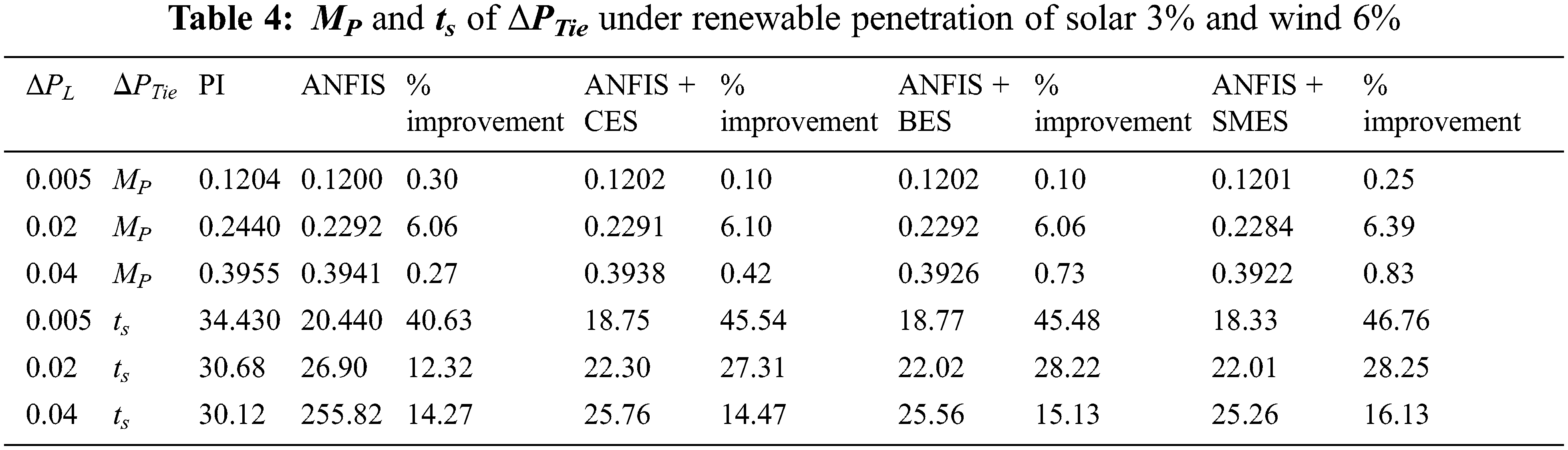
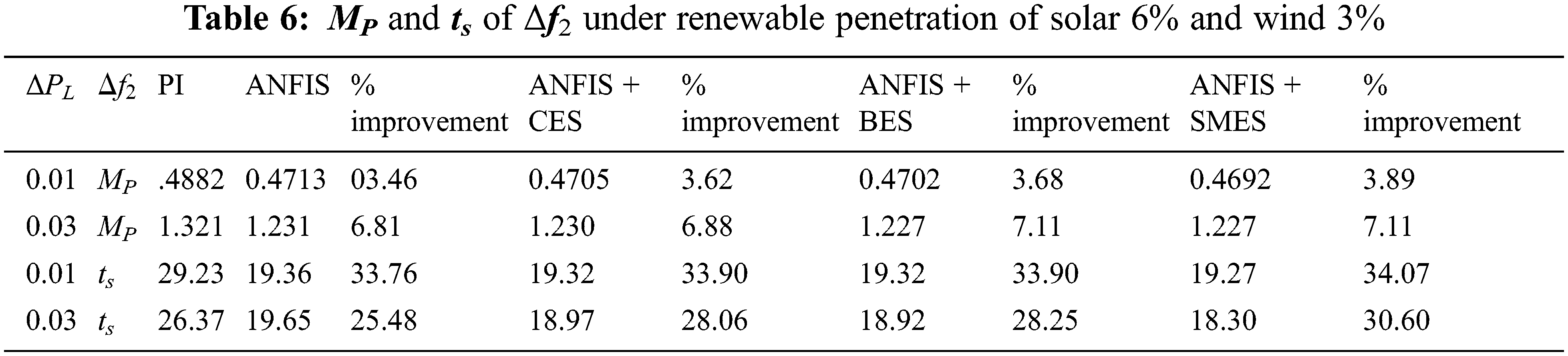
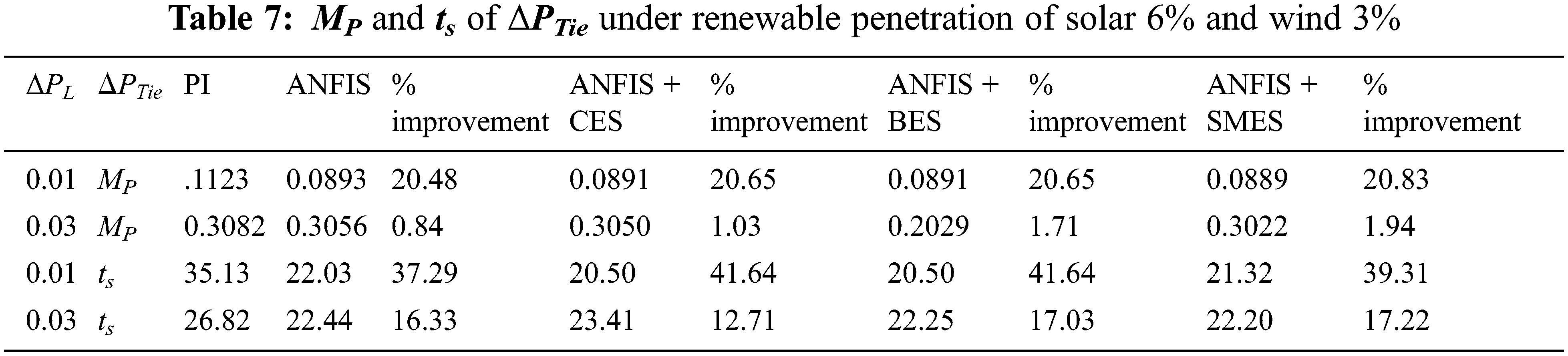
The system response was studied under multiple scenarios by varying the step load size from 0.005 to 0.04 p.u. A series of simulations were carried out with the ANFIS and PI controllers for the power system, as drawn in Fig. 3. Initially, the proportion of the RES in the installed capacity of AREA 1 is fixed at 6% from the solar unit and 3% from the wind generation unit. The comparative sheets for the three system variables, i.e., Δf1, Δf2, and ΔPtie have been prepared and are shown in Tabs. 2–7.
The effect of a storage unit on Δf1 and Δf2 was observed when a step load change happened. The variation in Δf1 for different controllers and the ESS units are shown in Fig. 13. The significance of the ANFIS controller is observed in the form of improvement in settling time (ts) and peak overshoot (MP). The storage units can provide active power in a short duration of time which helps to improve primary control. By introducing storage devices, the overall spike in frequency error is limited. From Fig. 13, it is clear that the operational performance of each ESS unit is different. Among the three ESS, the dynamic and steady-state performance of the SMES is best since it reduces both the MP and ts more as compared to the other storage units. On the other hand, the CES has the least effect on the performance in both transient and steady-state conditions. The response of the BES to step load change is slightly better than the CES.
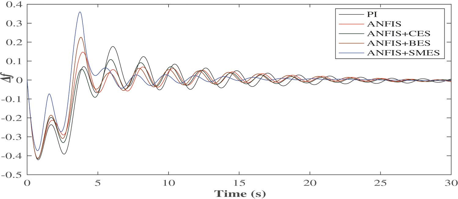
Figure 13: Dynamic performance of Δf1 (At ΔPL = 0.005 p.u.)
A shift in the load demand in AREA 1 affects the dynamic performance of the system frequency in the same area as well as in the connected AREA 2. As shown in Fig. 14, Δf2, the frequency error of AREA 2 has similarly improved results. It takes approximately 30 s to reach the zero steady-state error when only the PI controller is deployed. On the other hand, the ANFIS with SMES unit gives a zero steady-state error after 10 s only. In a nutshell, the combination of ANFIS and ESS units reduces this settling time between 10 and 15 s. The BES and CES also reduce the unwanted overshoot from the frequency oscillations; however, there is a lesser improvement than the SMES. The tie-line power deviation, ΔPTie is shown in Fig. 15.
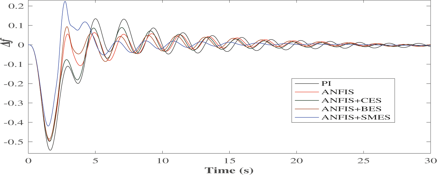
Figure 14: Dynamic performance of Δf2 (At ΔPL = 0.01 p.u.)
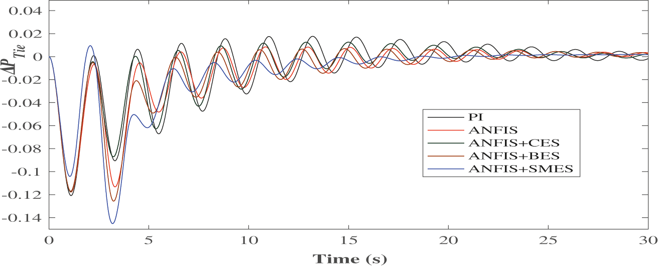
Figure 15: Dynamic performance of ΔPTie(ΔPL = 0.01 p.u.)
The performance statistics of different combinations of controllers and storage techniques are given in Tabs. 2–7. From Tab. 2, it is inferred that the peak overshoot increases with the increase in load perturbation level (ΔPL), but the settling time remains almost the same. The ts in the case of ANFIS is lesser than that in the case of PI controller. The BES and CES show a slight improvement in MP irrespective of the size of the disturbance. The improvement in MP in the case of SMES is moderate. Each storage unit has almost the same level of enrichment in steady-state performance. Overall, the SMES has a better dynamic and steady-state response. In Tab. 3, it is seen that as the step size ΔPL increases, the MP of Δf2 increases. In each case of load change, the improvement in MP using ANFIS is better than that of PI. When storage devices are connected, with the increase in ΔPL, even though the MP increases, the increment is less as compared to a controller-only case. However, a significant improvement appears in the steady-state response in the presence of energy storage devices. Among all the storage units, SMES has a better dynamic and steady-state performance. When analyzing the behavior of ΔPTie under different control strategies, a significant improvement in ts is observed, but improvement in MP is small. It is illustrated in Tabs. 2–4, the storage units improve the transient and steady-state behavior of both Δf1 & Δf2, whereas for ΔPTie improvement takes place only in the steady-state.
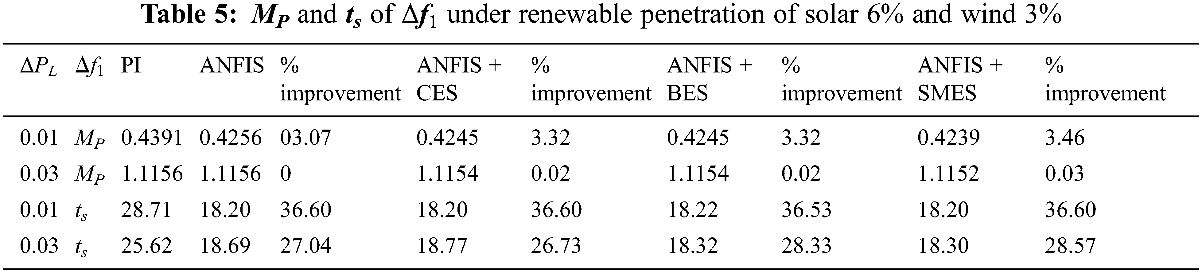
The behavior of Δf1, Δf2 and ΔPTie is given in Tabs. 5–7 when the renewable penetration level is reversed (6% for solar and 3% for wind). The simulations have been carried out for the two levels of load change ΔPL: one is 0.01 p.u. as the lower level of disturbance, and the other is 0.03 p.u. as the higher disturbance level. In Tabs. 5 and 6, the MP improves significantly for the lower level of disturbance, while a slight improvement is observed with a higher level of disturbance. The percentage improvement in ts also decreases for the larger disturbance. For ΔPTie, as ΔPL increases the substantial improvement appears in MP. However, there is a decline in percentage improvement as the load change increases. While focusing on ts, a significant improvement has been observed in all the cases. Among all, the SMES provides the most considerable enrichment.
To further assess the performance, the load perturbation level was set at 6% (0.06 p.u.), and the proportion of both solar and wind was set at 5%. The variation in Δf1 for different ESS under these conditions is depicted in Figs. 16–18.
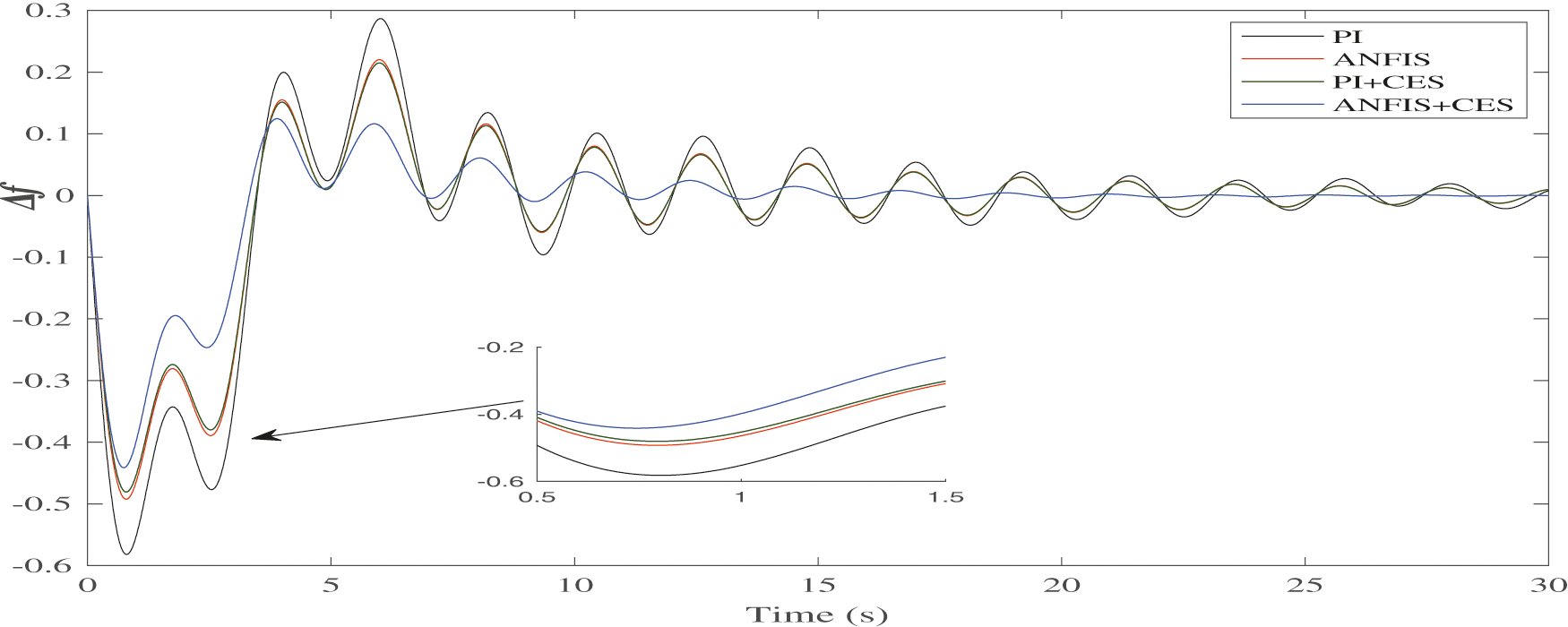
Figure 16: Variation in Δf1 for CES
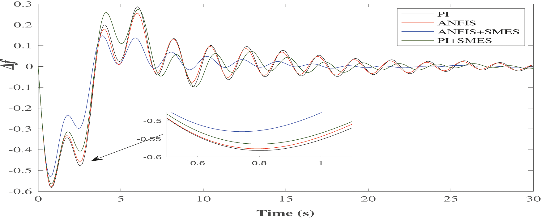
Figure 17: Variation in Δf1 for SMES
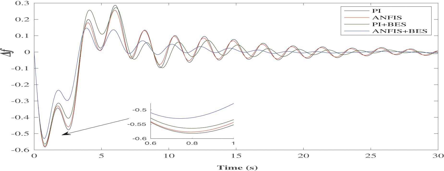
Figure 18: Variation in Δf1 for BES
It is clear that in the PI controller case, the frequency deviations are substantial. The variation in frequency decreases with the use of ANFIS. The deviation can be further reduced by introducing the ESS units. However, the ANFIS controller with SMES delivers the best results compared to the others, as presented in Fig. 17. The behavior of the BES unit with PI and ANFIS controllers has been presented in Fig. 18. It can be observed that the combination of intelligent controller and storage unit reduces the frequency regulations.
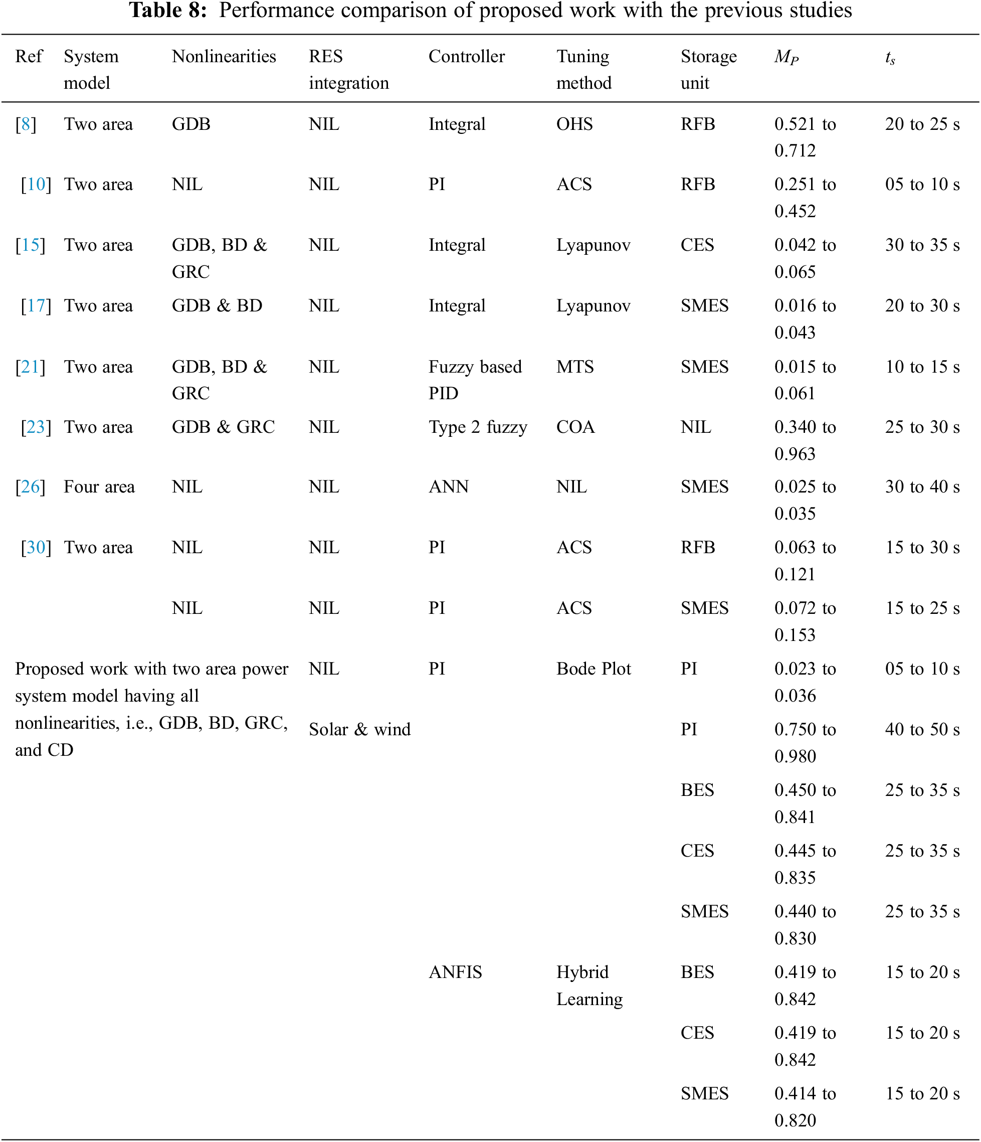
The proposed system’s performance comparison with other literature studies is presented in Tab. 8. In most of the studies, it can be observed that renewable penetration has not been included. A power system having RES has more inadvertent oscillations due to the fluctuating nature of the RES [19]. Moreover, if system nonlinearities are also modeled, even a minor disturbance may cause long-lasting fluctuations in Δf1, Δf2 and ΔPtie. Though the storage units help in improving the oscillatory response, the penetration of intermittent renewable resources could not be handled by the storage units alone. The results of the ANFIS controller in terms of MP and ts are better as compared to PI controller. The performance of the ANFIS controller along with the SMES storage unit is better as compared to other storage devices, in terms of MP. In terms of ts, the performance of the ANFIS controller is in the range of 15 to 20 s, whereas the PI has a larger settling time ranging from 25 to 35 s.
The analysis demonstrates that the ANFIS controller with SMES dampens power system oscillations better than a PI controller. The response is better for both the frequency and tie-line power deviations. The performance of the SMES is better as compared to BES and CES. Using SMES, ts reduces significantly, whereas a moderate reduction in peak overshoot of frequency deviation is observed.
In this paper, the performance of an ANFIS-based load frequency controller for a two-area power system has been investigated in the presence of renewable resources and storage units. All nonlinearities were taken into account while modeling the two-area system. Different storage technologies such as BES, CES, and SMES have been compared. The power network was analyzed with a broad range of variations in step load change and multiple levels of intermittent solar and wind generation. The PI-controlled system’s generated training data was then used to train the proposed ANFIS controller with and without storage units. The proposed controller performance was validated using two indices: peak overshoot and settling time. It was found that the energy storage units provided enrichment in the LFC performance over a conventional controller. The penetration of intermittent renewable resources could not be handled by the storage unit alone. Still, the combined performance of the ANFIS controller and storage unit is more effective. However, in the presence of storage units, the reduction in settling time is significant compared to the reduction in peak overshoot. Within the storage units, the best performance was obtained with the help of the SMES unit. The validation of the proposed work in a real-time laboratory, such as OPAL-RT, can be a part of future research work. The present work can also be extended for a significant penetration of renewable resources using a discrete controller.
Funding Statement: The authors received no specific funding for this study.
Conflicts of Interest: The authors declare that they have no conflicts of interest to report regarding the present study.
1. NERC, Committee and others, “Balancing and frequency control: A technical document prepared by the nerc resources subcommittee,” Princeton, US. NERC Technical report, 2011. [Online]. Available: https://www.nerc.com/docs/oc/rs/NERC. [Google Scholar]
2. R. Shankar, S. R. Pradhan, K. Chatterjee and R. Mandal, “A comprehensive state of the art literature survey on LFC mechanism for power system,” Renewable and Sustainable Energy Reviews, vol. 53, pp. 1185–1207, 2017. [Google Scholar]
3. H. H. Alhelou, M. E. Hamedani-Golshan, R. Zamani, E. Heydarian-Forushani and P. Siano, “Challenges and opportunities of load frequency control in conventional, modern and future smart power systems: A comprehensive review,” Energies, vol. 11, no. 10, pp. 2497, 2018. [Google Scholar]
4. N. Kouba, M. Menaa, K. Tehrani, and M. Boudour, “Optimal tuning for load frequency control using ant lion algorithm in multi-area interconnected power system,” Intelligent Automation and Soft Computing, vol. 25, no. 2, pp. 1–17, 2018. [Google Scholar]
5. L. Bird, M. Milligan and D. Lew, Report of Integrating Variable Renewable Energy: Challenges and Solutions, Golden, CO (USNational Renewable Energy Laboratory (NREL2013. [Google Scholar]
6. M. Anvari, G. Lohmann, M. Watcher, P. Milan, E. Lorenz et al., “Short term fluctuations of wind and solar power systems,” New Journal of Physics, vol. 18, no. 6, pp. 63027, 2016. [Google Scholar]
7. S. C. Johnson, J. D. Rhodes and M. E. Webber, “Understanding the impact of non-synchronous wind and solar generation on grid stability and identifying mitigation pathways,” Applied Energy, vol. 262, pp. 114492, 2020. [Google Scholar]
8. R. Shankar, K. Chatterjee and R. Bhushan, “Impact of energy storage system on load frequency control for diverse sources of interconnected power system in deregulated power environment,” Electrical Power and Energy Systems, vol. 79, pp. 11–26, 2016. [Google Scholar]
9. M. Cheng, S. S. Sami and J. Wu, “Benefits of using virtual energy storage system for power system frequency response,” Applied Energy, vol. 194, pp. 376–385, 2017. [Google Scholar]
10. Y. Arya, N. Kumar and S. K. Gupta, “Optimal automatic generation control of two-area power systems with energy storage units under deregulated environment,” Journal of Renewable and Sustainable Energy, vol. 9, no. 6, pp. 64105, 2017. [Google Scholar]
11. J. Li, R. Xiong, Q. Yang, F. Liang, M. Zhang et al., “Design/test of a hybrid energy storage system for primary frequency control using a dynamic droop method in an isolated microgrid power system,” Applied Energy, vol. 201, pp. 257–269, 2017. [Google Scholar]
12. P. Jood, S. K. Aggarwal and V. Chopra, “Impact of storage device on Load frequency control of a two-area renewable penetrated power system,” in Proc. IEEE Power India Int. Conf., Kurukshetra, India, pp. 1–6, 2018. [Google Scholar]
13. A. Adrees, J. Song and J. V. Milanovic, “The influence of different storage technologies on large power system frequency response,” in Proc. IEEE 8th Int. Power Electronics and Motion Control Conf., Hefei, China, pp. 257–263, 2016. [Google Scholar]
14. S. J. Lee, J. H. Kim, C. H. Kim, S. K. Kim, E. S. Kim et al., “Coordinated control algorithm for distributed battery energy storage systems for mitigating voltage and frequency deviations,” IEEE Transactions on Smart Grid, vol. 7, no. 3, pp. 1713–1722, 2016. [Google Scholar]
15. S. C. Tripathy, “Improved load-frequency control with capacitive energy storage,” Energy Conversion and Management, vol. 38, no. 6, pp. 551–562, 1997. [Google Scholar]
16. V. Mukherjee and S. P. Ghoshal, “Application of capacitive energy storage for transient performance improvement of power system,” Electric Power Systems Research, vol. 79, no. 2, pp. 282–294, 2009. [Google Scholar]
17. S. C. Tripathy, R. Balasubramanian and P. S. C. Nair, “Adaptive automatic generation control with superconducting magnetic energy storage in power systems,” IEEE Transactions on Energy Conversion, vol. 7, no. 3, pp. 434–441, 1992. [Google Scholar]
18. M. Farahani and S. Ganjefar, “Solving LFC problem in an interconnected power system using superconducting magnetic energy storage,” Physica C: Superconductivity, vol. 487, pp. 60–66, 2013. [Google Scholar]
19. P. Jood, S. K. Aggarwal and V. Chopra, “Performance assessment of a neuro-fuzzy load frequency controller in the presence of system nonlinearities and renewable penetration,” Computers and Electrical Engineering, vol. 74, pp. 362–378, 2019. [Google Scholar]
20. M. Rahmani and N. Sadati, “Hierarchical optimal robust load-frequency control for power systems,” IET Generation, Transmission and Distribution, vol. 6, no. 4, pp. 303–312, 2012. [Google Scholar]
21. S. Pothiya and I. Ngamroo, “Optimal fuzzy logic-based PID controller for load–frequency control including superconducting magnetic energy storage units,” Energy Conversion and Management, vol. 49, pp. 2833–2838, 2008. [Google Scholar]
22. H. Bevrani, F. Habibi, P. Babahajyani, M. Watanabe and Y. Mitani, “Intelligent frequency control in an AC microgrid: Online PSO based fuzzy tuning approach,” IEEE Transactions on Smart Grid, vol. 3, no. 4, pp. 1935–1944, 2012. [Google Scholar]
23. M. E. Baydokhty, A. Zare and S. Balochian, “Performance of optimal hierarchical type 2 fuzzy controller for load–frequency system with production rate limitation and governor dead band,” Alexandria Engineering Journal, vol. 55, no. 1, pp. 379–397, 2016. [Google Scholar]
24. Y. K. Bhateshvar, H. D. Mathur and R. C. Bansal, “Power-frequency balance in multi-generation system using optimized fuzzy logic controller,” Electric Power Components and Systems, vol. 45, no. 12, pp. 1275–1286, 2017. [Google Scholar]
25. K. R. Sudha and R. V. Santhi, “Load frequency control of an interconnected reheat thermal system using type-2 fuzzy system including SMES units,” International Journal of Electrical Power & Energy Systems, vol. 43, no. 1, pp. 427–433, 2012. [Google Scholar]
26. A. Demiroren, “Automatic generation control using ANN technique for multi area power system with SMES,” Electric Power Components and Systems, vol. 32, no. 2, pp. 193–213, 2004. [Google Scholar]
27. M. I. Mosaad and F. Salem, “LFC based adaptive PID controller using ANN and ANFIS techniques,” Journal of Electrical Systems and Information Technology,” vol. 1, no. 3, pp. 212–222, 2014. [Google Scholar]
28. G. Panda, S. Panda and C. Ardil, “Hybrid neuro fuzzy approach for automatic generation control of two–area interconnected power system,” World Academy of Science, Engineering and Technology, vol. 5, no. 10, pp. 80–84, 2011. [Google Scholar]
29. S. Prakash and S. K. Sinha, “Load frequency control of multi-area power systems using neuro-fuzzy hybrid intelligent controllers,” IETE Journal of Research, vol. 61, no. 5, pp. 526–532, 2015. [Google Scholar]
30. R. K. Selvaraju and G. Somaskandan, “Impact of energy storage units on load frequency control of deregulated power systems,” Energy, vol. 97, pp. 214–228, 2016. [Google Scholar]
31. A. Pappachen and A. P. Fatima, “Load frequency control in deregulated power system integrated with SMES–TCPS combination using ANFIS controller,” International Journal of Electrical Power & Energy Systems, vol. 82, pp. 519–534, 2016. [Google Scholar]
32. T. T. Teo, T. Logenthiran, W. L. Woo and K. Abidi, “Fuzzy logic control of energy storage system in microgrid operation,” in Proc. IEEE Innovative Smart Grid Technologies, Melbourne, VIC, Australia, pp. 65–70, 2016. [Google Scholar]
33. M. Ud din Mufti, S. A. Lone, S. J. Iqbal, M. Ahmad and M. Ismail, “Super-capacitor based energy storage system for improved load frequency control,” Electric Power Systems Research, vol. 79, no. 1, pp. 226–233, 2009. [Google Scholar]
34. R. J. Abraham, D. Das and A. Patra, “Effect of capacitive energy storage on automatic generation control,” in Proc. IEEE Int. Power Engineering Conf., Singapore, pp. 1070–1074, 2005. [Google Scholar]
35. H. J. Kunisch, K. G. Kramer and H. Dominik, “Battery energy storage another option for load-frequency-control and instantaneous reserve,” IEEE Transactions on Energy Conversion, vol. 1, pp. 41–46, 1986. [Google Scholar]
36. J. Figgener, P. Stenzel, K. P. Kairies, J. Linben, D. Heberschusz et al., “The development of stationary battery storage systems in Germany–A market review,” Journal of Energy Storage, vol. 29, pp. 1–20, 2020. [Google Scholar]
37. R. K. Selvaraju and G. Somaskandan, “ACS algorithm tuned ANFIS-based controller for LFC in deregulated environment,” Journal of Applied Research and Technology, vol. 15, pp. 152–166, 2017. [Google Scholar]
38. S. B. Shree and N. Kamaraj, “Hybrid neuro fuzzy approach for automatic generation control in restructured power system,” International Journal of Electrical Power & Energy Systems, vol. 74, no. 1, pp. 274–285, 2016. [Google Scholar]
39. G. Sharma, I. Nasiruddin, K. R. Niazi and R. C. Bansal, “ANFIS based control design for AGC of a hydro-hydro-power system with UPFC and hydrogen electrolyzer units,” Electric Power Components and Systems, vol. 46, no. 4, pp. 406–417, 2018. [Google Scholar]
 | This work is licensed under a Creative Commons Attribution 4.0 International License, which permits unrestricted use, distribution, and reproduction in any medium, provided the original work is properly cited. |