DOI:10.32604/iasc.2022.025396
| Intelligent Automation & Soft Computing DOI:10.32604/iasc.2022.025396 | |
| Article |
Evolutionary Algorithm Based Z-Source DC-DC Boost Converter for Charging EV Battery
1Department of Electrical and Electronics Engineering, University VOC College of Engineering, Tuticorin, 628008, India
2Department of Electrical and Electronics Engineering, National Engineering College, Kovilpatti, 628503, India
*Corresponding Author: K. Karthik Kumar. Email: karthikpapers2021@gmail.com
Received: 22 November 2021; Accepted: 18 January 2022
Abstract: In this paper, efficient charging of electric vehicle battery from a considered renewable solar photovoltaic source with the help of a modified Z source with efficient boosting topology. Adapting this Z-source converter to act as a voltage gainer with a boosting function allows a solar Photovoltaic (PV) input voltage of 25VDC (Volts Direct Current) to be increased to a designed output voltage of 75VDC at a low duty ratio, resulting in minimal switching loss. The closed-loop steady-state and transient parameters at the output were analyzed and compared using modern evolutionary algorithms. The power range upheld throughout the circuit is around (300–350) W. The battery is assumed to have an impedance model of Resistor-Capacitor (RC) load with a serial range of 12 V and 7 Ah. The proposed converter achieves higher conversion efficiency by the Maximum Power Pont Tracking (MPPT) and NSGA-II/MNSGA-II (non-dominated sorting genetic algorithm) based controller algorithm for tuning the optimal design value and is validated in a MATLAB Simulink platform. In this work, we analyze closed-loop systems under the mentioned power range. The MPPT with an algorithm-based controller tends to trigger the switch in the closed-loop system to get the optimized output. The Maximum Power Point (MPP) technique implemented is an incremental conductance method for extracting solar PV power and improving load performance. Consequently, the proposed evolutionary optimization algorithm steady-state ripple factor response of the proposed MNSGA-II has a lower output side, thus achieving around 98% of the controller implementation efficiency.
Keywords: Solar photovoltaic; voltage gainer; RC (resistive and capacitive load); parasitic circuit; NSGA-II; MNSGA-II
In today’s world, renewable energy plays a crucial role in electrical energy conversion systems. The research is towards achieving a highly efficient power conversion system while integrating with renewable energy sources. The various boost, buck, and buck-boost topologies were involved in this research analyzed with different control methodologies to prove its technical uniqueness. Most of the literature defines eliminating technical parameters like ripple current and voltage at the parasites present in the system by implementing various multi-objective evolutionary algorithm-based controllers. Thus, this could improve the reliability and efficiency of the system.
There are various evolutionary algorithms like Particle Swarm Optimization (PSO), Genetic Algorithms (GA), and Grey Wolf Optimizer (GWO) algorithm are used for tuning Proportional Integral Derivative (PID) controller gain parameters in the conventional boost converter for getting the better optimal solution and root mean square error (RMSE) values than the conventional PID controller for different load conditions [1,2]. However, the performance of the older boosting operation decreases due to the improper selection of capacitors and inductors. In [3], a switched type Z-source/Quasi Z source converter is employed with reduced passive components in the PV grid-connected system to achieve high gain at small duty with the conventional tuning techniques. In addition to PSO and GA, metaheuristic and tabu optimization is implemented to find the optimal gain values to obtain the constant output voltage for both loaded and non-loaded conditions [4]. With the help of the state-space averaging method, the reduced-order tuning parameters are derived for interleaved type Single Ended Primary Inductor Converter (SEPIC) converter to expand the dynamic performance of the scheme by using the genetic algorithm-based controllers [5]. The PI controller [6] is tuned by PSO optimization employed in a bridgeless Luo converter to get an optimum design to produce a high-efficiency output and the performance study is made between Zeigler Nicholas and PSO method [7].
In [8] a hybrid evolutionary-based algorithm is used in a photovoltaic system combined with a boost converter to improve the MPPT performance under partial shading conditions. Furthermore, the performance analysis between conventional PSO [9] and hybrid evolutionary algorithm (PSO and (differential evaluation) DE) is done. A model predictive control algorithm is proposed for an MPPT based photovoltaic system that reduces the overall system cost and makes it operate in an adaptive step size [10]. An improved interleaved boost converter exhibits low ripple output voltage using a PSO-based type III optimal controller that provides high efficiency during energy conversion [11]. A cost-effective fuzzy-based MPPT control in [12] provides high efficient energy conversion under various operating conditions for the entire scheme’s steady-state and transient analysis.
A non-dominated sorting genetic algorithm (NSGA-II) was implemented as a multi-objective Pareto optimal model for the metal mining process to improve the production efficiency and utilization rate [13,14]. The MPPT with differential evolution algorithm [15] is used in solar PV-assisted SEPIC converter for getting quick response under different partial shading [16] and load conditions [17,18]. The improved efficiency and low-cost system are achieved with the help of a power balancing point optimization algorithm for PV system assisted differential power processing converter [19]. The modular multilevel converter is injected with second and third-order harmonics using a multi-objective genetic algorithm for reducing voltage ripples at the capacitor in [20]. The cuckoo optimization algorithm is developed in a boost converter for tuning the PI controller and the outcomes are compared with conventional PI controller parameters [21]. The fractional type PID controller is digitally implemented and the results are compared with ordinary PID controller [22]. An optimized algorithm improves the complete system stability with a passive filter present in the Alternate Current-Direct Current (AC-DC) converter [23].
ZSBC is a converter that will operate in high voltage gain and high reliability compared to the existing converter [24]. High frequency and coupled inductors are used to increase the voltage gain of the Modified Z-Z-Score Boost Converter (MZSBC) [25–27]. As a result, the voltage gain has been enhanced while the duty cycle of the switch has not been limited. However, the duty cycle has been limited. Therefore, a combined switched-inductors switched-capacitor has been utilized to upgrade the converter. To overcome these limitations, the concept of Z-source was introduced in [28–31]. A high voltage gain is obtained by using three winding inductors and switched capacitors [32]. To eliminate the dead time production one stage conversion of impedance circuit is introduced in [33]. However, energy occurs due to variations in the charging and discharging process [34]. Therefore, the PI controller system efficiency is improved even if the system’s reference voltage varies [35].
Therefore, the problems caused by partial shading such as low voltage gain and drop in power level are tedious while integrating solar PV with a power conversion system [36] for charging a battery bank. To enhance the system performance, a proper PID controller with better gain parameters must be employed but, in the conventional boosting topology with PID controller [37] tuning design provides more ripple voltage at the output side, high switching losses and thus, resulting in the low efficiency of the system which is considered as the problem of multi-objective.
To eliminate those above problems, the Solar PV integrated MZSBC converter with MPPT and MNSGA-II multi-objective optimization is proposed which highlights the following objective:
a) The MZBC is designed to produce a high voltage gain at a small duty ratio and high frequency due to the presence of coupled inductor with reduced switching losses.
b) The incremental conductance MPP technique helps to improve the load side performance with derived maximum power from the PV.
c) The MPPT and MNSGA-II optimization are used to improve the PID controller optimal gain values, the system’s dynamic performance and reduce the integral square error, which causes the system to achieve high efficiency with low-efficiency ripples at the output side.
d) The PID tuned gain parameters and time domain specifications like rising time, overshoot, settling time, and steady-state error obtained from different optimization algorithms are compared with the proposed MNSGA-II algorithm to show its technical importance.
e) By considering the efficiency, duty ratio, and controller, a comparison is made between existing and proposed converter performance.
In general, converters are electrical devices that convert voltage from alternating current (AC) to direct current (DC). This modified Z-source converter has a unique boost-up converting system that boosts input low voltage source to the designed output voltage, it gains an outcome at minimum switching loss by having a better control technique. Fig. 1 depicts the architecture of the proposed converter where the solar PV is used for charging the EV battery with an MZSBC converter. PI controller triggers the switches by comparing the actual and reference values to generate an error signal. The controller gain values are tuned by MPPT and MNSGA-II optimization algorithm. The pulse width modulation is a power amplifier that accepts the low power input from the controller board and generates a high current drive input for the gate of a power MOSFET. The simulation and hardware setup are developed for the proposed topology.

Figure 1: Proposed DC to DC modified Z-sourced converter battery architecture
Fig. 2 displays a closed-loop structure of the proposed converter which consists of solar PV, MZSBC, MPPT&MNSGA-II controller and RC load as battery impedance. The MZSBC comprises diode D1, an intermediate element between the PV and converter, coupled inductor La and Lb, connected through a capacitor element Ca and Cb, Switch SW for turn ON/OFF purpose and, the filter components LcCc respectively. The MPPT and MNSGA-II controller generates a pulse to trigger the switch Sw and provide maximum power to the load. The main moto of the Z source converter in the motor vehicle gives a high gain and it attains better performance and efficiency of 98% through evolutionary data. From this evolutionary algorithm boosts up DC low voltage to DC high voltage. Therefore it mainly focused on less switching loss using a modified Z-source DC-DC boost converter employing solar energy.

Figure 2: Proposed control closed-loop circuit diagram of the DC-DC converter
In Fig. 3 mode 1 operation, when switch Sw is ON, the diode will be reverse biased it will be an open circuit and the capacitors can charge the inductors; whether the circuit is in a shoot-through zero state.

Figure 3: Mode 1 operation of the proposed converter
When the sum of two capacitors voltage is greater than the input voltage,
The voltage across the inductors are,
In the mode 1 operation, there are the two voltage capacitors as voltage capacitor VCa and voltage capacitor VCb and input voltage as Vi. From the equation, the voltage across inductors is equal to voltage across the capacitor.
In Fig. 4 mode 2 operation diode D1 is ON and switch Sw is OFF. When the switch Sw is turned OFF, the voltage across it keeps increasing until the input diode. D1 is turned ON. So, the voltage across the switch is clamped. In this operation mode, the voltage across inductors La is induced across inductors Lb Therefore, capacitors Ca and Cb are charged in this operation mode. Furthermore, the capacitors Cc and the filter inductor Lc are charged in this mode.
where,
ILa is the inductor current at a
ICa is the capacitor current at a

Figure 4: Mode 2 operation of the proposed converter
As a result, the inductor current becomes zero and maintains the following switching action; therefore, this mode can isolate both the dc source and load,
Therefore, the input current value is greater than zero.
3 Importance of MNSGA-II Algorithm
The NSGA-II algorithm has advantages like elitism, non-dominated, ranking, and crowding distance, leading to rapid convergence to optimal solutions. The NSGA-II is developed in many kinds of literature. The modified NSGA-II is implemented to solve elitism, fast non-dominated sorting approach, and diversity along with the Pareto optimal search. However, lateral diversity is still unchanged and non-dominated solutions are distributed standardized to the Pareto front. To avoid this drawback dynamic crowding distance (DCD)-based modified non-dominated sorting genetic algorithm-II (MNSGA-II) was proposed to improve the distribution of non-dominated solutions [18].
The crowding distance equation is given below,
where,
CDi is the crowding distance
The crowding distance is the value of a certain mean distance solution of its two neighboring solutions. Where CDi is the crowding distance of the ith solution; r is the number of objectives;
Individual variance (5) of the CDs with neighbors of the ith solution gives data about the different degrees of CD in different objectives.
The non-dominated sorting approach is modified with the implementation of the DCD technique. The step-by-step procedural flow of the proposed MNSGA-II incorporating DCD is given below.
1. Identify the Control Variable like output voltage.
2. Select the parameters like the number of population, the maximum number of generations, crossover and mutation probabilities.
3. Generate the initial population and evaluate the objective functions.
4. Set the generation count i = 0.
5. Perform simulated binary crossover and polynomial mutation.
6. Perform non dominated sorting for combined parent population and offspring population.
7. Generate population for next-generation from combined parent and offspring population using DCD.
8. Perform parent selection based on tournament selection.
9. i < imax
Hence, the diversity of MNSGA-II and the Pareto optimal front is obtained with high uniformity.
3.1 Specification of Proposed Converter
The function to be minimized is,
Subject to xl < x < xu
f1 = ISE of desired output voltage
f2 = ISE of ripple in output voltage
where xl and xu are the lower and upper bounds of variables; x= {Kp, Ki, Kd and C}; T is the simulation period length. The lower and upper bounds of PID parameters of desired output voltage where Kp∈[0,15], Ki∈[0,100], Kd∈[0,1] and C = {50, 150, 250, 450, 850}.
4 Closed-Loop Implementation of the Proposed Topology Using MATLAB Software
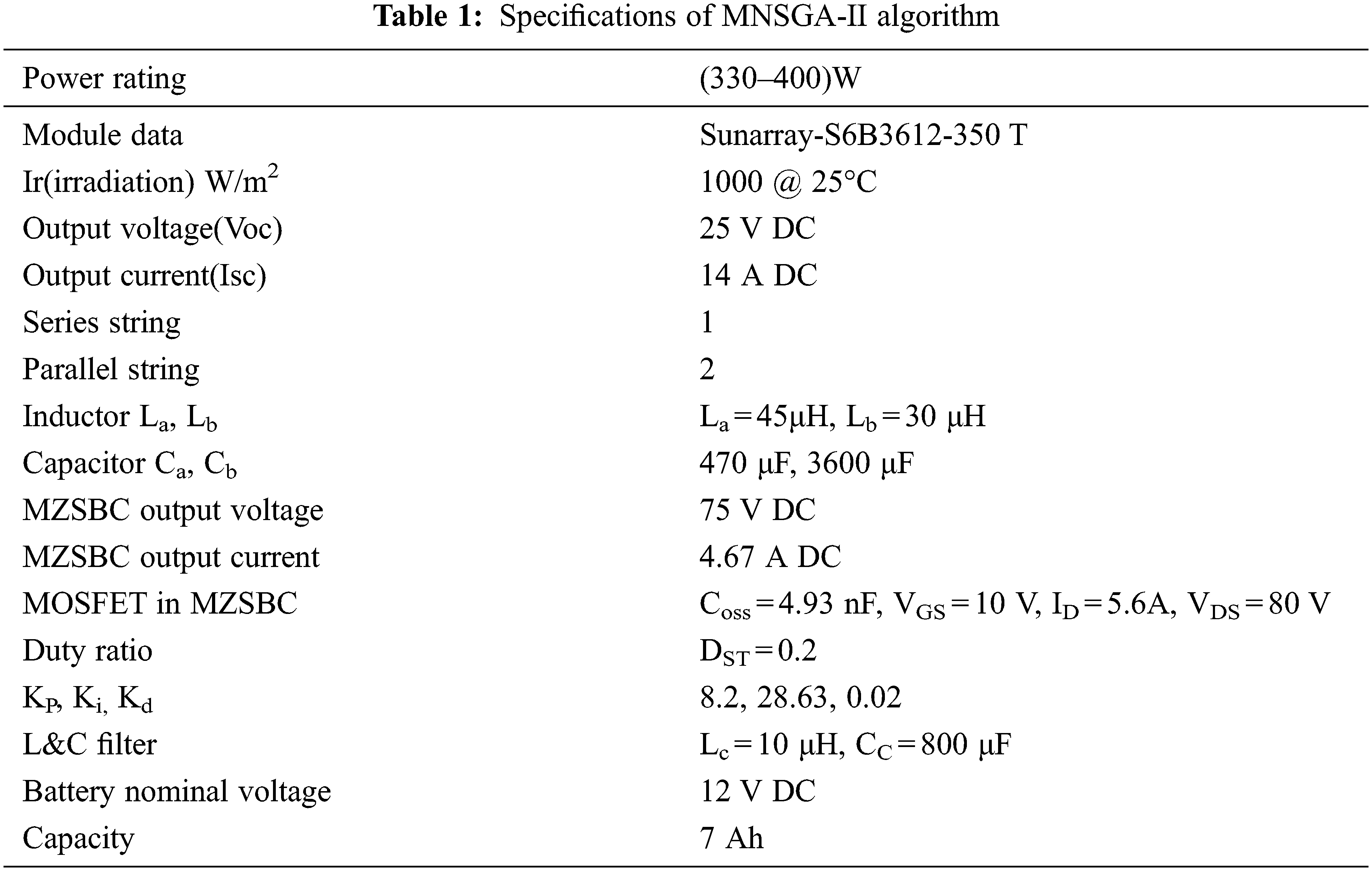
The proposed topology is simulated in the MATLAB Simulink platform and is depicted in Fig. 5. The specification details of the proposed circuit are given in Tab. 1. At 1000 W/m2 irradiation and 0°C temperature, the solar panel provides 25 V DC, 14 A DC power given as input to MZSBC and is boosted to 75 V DC, 4.6 A DC with a gain value of three. The power switches are triggered with the PID controller with two different proposed algorithms, like NSGA-II and MNSGA-II, for multi-objective functions, as shown in Fig. 6. The optimal Kp, Ki, Kd and C solution can be selected by minimizing the integral square error value of desired and ripple output voltage, respectively. The initial parameter values used in different algorithms are shown in Tab. 2.

Figure 5: Closed-loop simulink of the proposed converter

Figure 6: Operation diagram of the PID controller using NSGA/MNSGA optimization to control modified Z-source boost converter circuit voltage
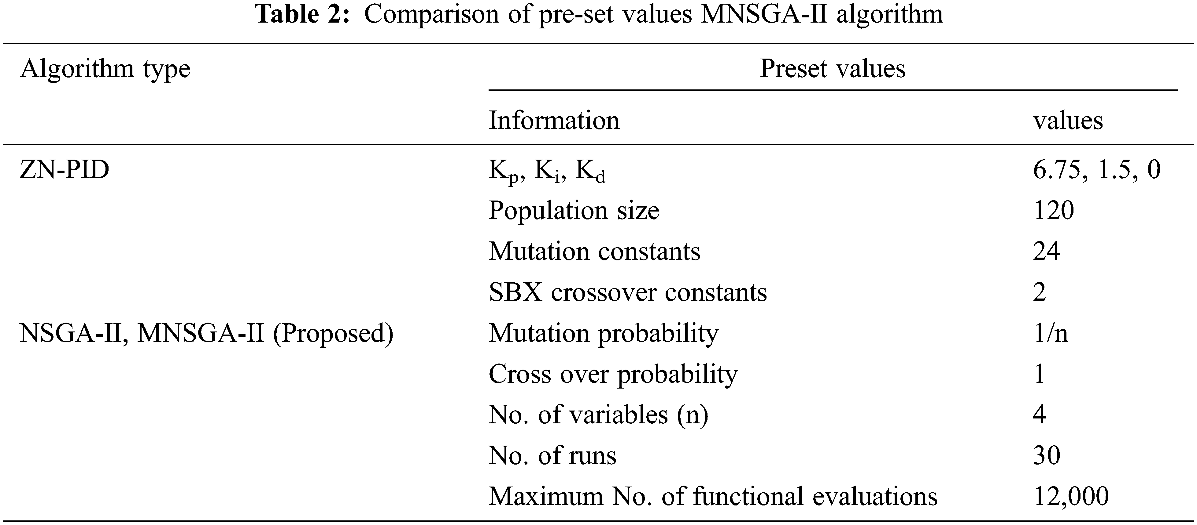
4.1 Pre-Set Values of the Different Algorithm Type
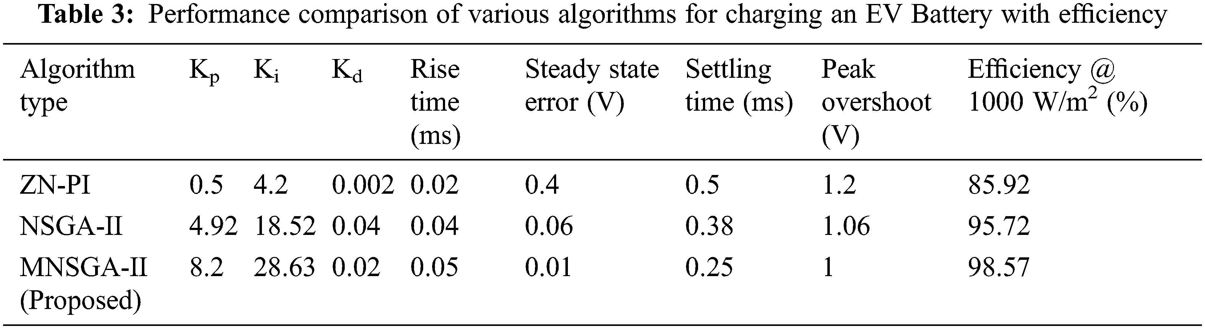
The Pareto optimal solution for ISE of ripple in the output voltages of NSGA-II and MNSGA-II is depicted in Fig. 8. A comparison is made between ISE of ripple in output voltage and ISE of desired output voltage in the Pareto optimal solution. The optimal gain values Kp, Ki, Kd are tuned by the PID controller which NSGA-II and MNSGA-II obtain to reach the multi-objective optimization. Comparative performance of existing and proposed algorithm type with MZSBC is tabulated in Tab. 3. The comparative chart is built-in Fig. 7 between algorithm type as well as efficiency @ 1000 W/m2.

Figure 7: Comparison chart between algorithm type and efficiency (%) for different converters

Figure 8: Pareto-optimal front using (a) NSGA-II, (b) MNSGA-II for MZSBC
4.2 Comparative Performance of Proposed Topology Using Existing and Proposed Algorithm
The constant temperature of 25°C and change in irradiation with time is depicted in Fig. 9. Fig. 10 depicts the flowchart of the incremental conductance method, an MPPT algorithm used for MPP tracking to provide optimal power to the load for improving the load performance.

Figure 9: Irradiation and temperature chart

Figure 10: Incremental conductance method flow chart
Fig. 11 shows the PV and IV curves obtained from the solar panel once the MPPT is included. The panels provide 350 W power with 25 V DC and 14 A DC as input to the MZSBC.

Figure 11: IV and PV curve
4.3 MATLAB Simulation Results and Analysis of the Proposed Converter
The PID controller-based MPPT and NSGA-II and MNSGA-II tuning contribution of this work is to increase the response of MZSBC with a feedback system. The MPP technique used is the incremental conductance algorithm. The input voltage 25 V is boosted to 75 V while tuned by MPPT and NSGA-II/MNSGA-II based controllers, shown in Figs. 12, 13, 15, and 16. The steady-state output voltage and current waveform of the proposed MPPT and MNSGA controller-based MZSBC is shown in Figs. 15 and 16. The output response of MZSBC is compared while tuned with MPPT and NSGA-II as well as MNSGA-II PID controller. On comparing both the controllers, the initial damping is reduced in the MNSGA-II technique. As a result, the ripple content of NSGA-II and MNSGA-II are 0.6 and 0.045 V as shown in Figs. 14 and 17.

Figure 12: Simulation output voltage waveform of proposed converter NSGA-II

Figure 13: Simulation output current waveform of proposed converter NSGA-II

Figure 14: Simulation ripple output voltage of proposed converter NSGA-II method

Figure 15: Simulation output voltage waveform of proposed converter MNSGA-II

Figure 16: Simulation output current waveform of proposed converter MNSGA-II

Figure 17: Simulation ripple output voltage of proposed converter MNSGA-II method
Hence, the ripple content in the output response gets reduced in the MNSGA-II technique. Therefore, it is clearly shown that the NSGA-II method oscillates between 75.3 and 74.7 obtaining ripples of 0.6 V whereas, the MNSGA-II method oscillates between 75.035 and 74.99 obtaining 0.045 V ripples. The dynamic performance analysis of solar PV integrated MZSBC of the output voltage 75 V is created in input voltage by changing the magnitude from 25 to 45 V which is created at t = 0.5 s and the input is reinstated at t = 0.54 s which is indicated in Fig. 18. According to the simulation results of MZSBC, it would be more advantageous and delivers high output power with lower input voltage peak overshoot.

Figure 18: Simulation dynamic response of proposed converter for change in input voltage (a) output voltage (b) Output current
The step responses of ZN-PID, NSGA-II, and robust are shown in Fig. 19, amplitude vs. time in seconds graph and it clearly shows that the settling time, peak overshoot, steady-state error, and transients are better in the MNSGA-II algorithm compared to the other two methods. In addition, a reference voltage variation analysis is made for finding the optimal efficiency during the MNSGA-II controller implementation with MZSBC and is tabulated in Tab. 4 and the performance measures of the proposed converter as compared to existing topologies is tabulated in Tab. 5.

Figure 19: Step response for ZN, NSGA-II and MNSGA-II
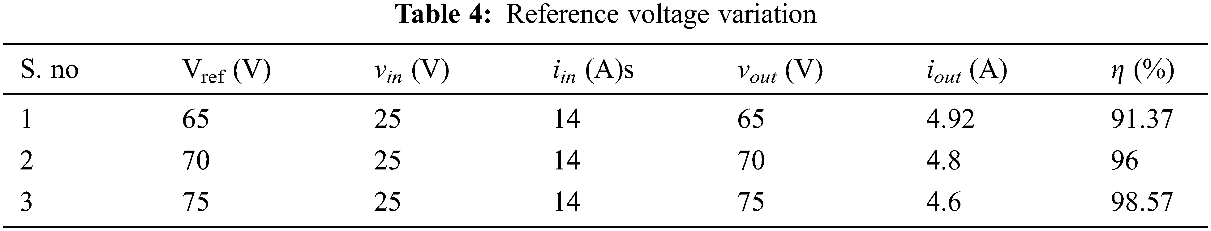
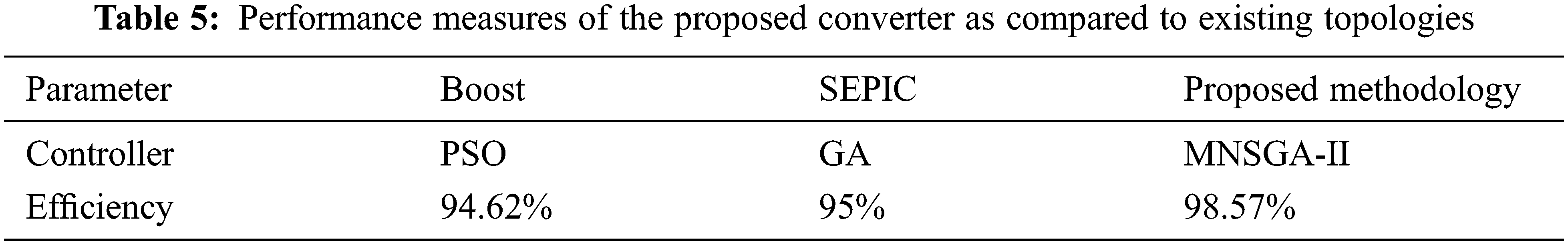
Fig. 20 shows the battery model simulated on MATLAB. This lithium battery model’s equivalent impedance is calculated and evaluated as a resistor-capacitor load for analysis.

Figure 20: Battery model proposed converter
5 Experimental Setup and Results of MZSBC
The experimental result section includes the hardware setup of the proposed MNSGA-II-based MZSBC converter system with the simulation dynamic reponse and ripple in the output voltage and output current waveform using the MNSGA-II method.
Fig. 21 shows the experimental setup of the proposed work when using MPPT and MNSGA-II based PID algorithm.

Figure 21: Hardware setup for the MNSGA-II-based MZSBC converter
FPGA Controller is established to trigger pulses for the power semiconductor switch and the generated pulse waves for the proposed optimization algorithm are depicted in Fig. 22.

Figure 22: Triggering pulse using MNSGA-II method
The dynamic performance study while changing input voltage and the output responses are shown in Fig. 23 and enlarged view of dynamic response is shown in Fig. 24.

Figure 23: Experimental results of dynamic response

Figure 24: Enlarged view of dynamic response
Fig. 25 shows the steady-state output response with ripple content. Simulation and hardware outputs are almost the same since 25 V DC from solar PV is boosted to 75 V DC with a ripple value of 0.045 V. Hence, an efficient topology is designed. As a result of the proposed methodology, there is less switching loss, improving power load performance. An evolutionary algorithm-based controller enhances the system’s efficiency and reliability. The proposed MPPT and NSGA-II/MNSGA-II algorithms improve the dynamic and steady-state performances of the system. It is apparent from the output voltage and outputs current waveforms that the performance linearly increases from 0.91 to 0.99. The proposed converter MNSGA-II evolutionary algorithm achieves a better efficiency of 98% at the maximum iteration rate.

Figure 25: Hardware results of ripple in the output voltage and output current waveform using the MNSGA-II method
This paper concentrates on an efficient way of charging an electric vehicle battery with a good battery and equivalent impedance models. A boosting topology is employed to charge a battery better and act as a charge controller. The power range of 350 W is utilized to charge a battery of serial 12 V, 7 Ah pack. The MZSBC converter gives a high gain from 25 V DC to 75 V DC with a small duty ratio that provides higher efficiency at the boosting level. The closed-loop simulation with different performance analyses is achieved. The PID controller gain parameters are tuned with an MPPT and NSGA-II/MNSGA-II algorithm, improving the system’s dynamic and steady-state performance. Also, the ripple content is reduced on the output side. The efficiency obtained is around 98%. A comparative study is made between proposed and existing boost converter topologies considering the efficiency and algorithm type. The simulation and hardware implementation with the best results were obtained. The dynamic performance with change in input voltage is analyzed and the reference voltage variation analysis is made to find the optimal efficiency of the proposed converter.
Acknowledgement: The authors with a deep sense of gratitude would thank the supervisor for his guidance and constant support rendered during this research.
Funding Statement: The authors declare that they have no conflicts of interest to report regarding the present study.
Conflicts of Interest: The authors declare that they have no conflict of interest.
1. J. A. Leon, C. C. Palacios, C. V. Salgado, E. H. Perez and E. X. M. Garcia, “Particle swarm optimization, genetic algorithm and grey wolf optimizer algorithms performance comparative for a DC-DC boost converter PID controller,” Advances in Science, Technology and Engineering Systems Journal, vol. 6, no. 1, pp. 619–625, 2021. [Google Scholar]
2. G. S. Rao, S. Raghu and N. Rajasekaran, “Design of feedback controller for boost converter using optimization technique,” International Journal of Power Electronics and Drive Systems, vol. 3, no. 1, pp. 117–128, 2013. [Google Scholar]
3. J. Liu, J. Wu, J. Qiu and J. Zeng, “Switched Z-source/quasi-Z-source DC-DC converters with reduced passive components for photovoltaic systems,” IEEE Access, vol. 7, pp. 40893–40903, 2019. [Google Scholar]
4. I. Laoprom and S. Tunyasrirut, “Design of PI Controller for Voltage Controller of Four-Phase Interleaved Boost Converter Using Particle Swarm Optimization,” Journal of Control Science and Engineering, vol. 2020, 2020. http://dx.doi.org/10.1155/2020/9515160. [Google Scholar]
5. C. Komathi and M. G. Umamaheswari, “Analysis and design of genetic algorithm-based cascade control strategy for improving the dynamic performance of interleaved DC–DC sepic pfc converter,” Neural Computing and Applications, vol. 32, no. 9, pp. 5033–5047, 2020. [Google Scholar]
6. A. Iqbal, M. Meraj, B. Tariq, K. A. Lodi, S. Rahman et al., “Experimental investigation and comparative evaluation of standard level shifted multi-carrier modulation schemes with a constraint GA based SHE techniques for a seven-level PUC inverter,” IEEE Access, vol. 7, pp. 100605–100617, 2019. [Google Scholar]
7. R. K. Selvi, R. Suja and M. Malar, “A bridgeless Luo converter-based speed control of switched reluctance motor using particle swarm optimization (Pso) tuned proportional integral (Pi) controller,” Microprocessors and Microsystems, vol. 75, pp. 103039, 2020. [Google Scholar]
8. M. Joisher, D. Singh, S. Taheri, D. R. E. Trejo, H. Taheri et al., “A hybrid evolutionary-based MPPT for photovoltaic systems under partial shading conditions,” IEEE Access, vol. 8, pp. 38481–38492, 2020. [Google Scholar]
9. K. Sundareswaran, V. Devi, S. Sankar, P. S. R. Nayak and S. Peddapati, “Feedback controller design for a boost converter through evolutionary algorithms,” IET Power Electronics, vol. 7, no. 4, pp. 903–913, 2014. [Google Scholar]
10. O. A. Rahim, “A new high gain DC-DC converter with model-predictive-control based MPPT technique for photovoltaic systems,” CPSS Transactions on Power Electronics and Applications, vol. 5, no. 2, pp. 191–200, 2020. [Google Scholar]
11. S. Banerjee, A. Ghosh and N. Rana, “An improved interleaved boost converter with PSO-based optimal type-III controller,” IEEE Journal of Emerging and Selected Topics in Power Electronics, vol. 5, no. 1, pp. 323–337, 2017. [Google Scholar]
12. A. S. Mohamed, A. Berzoy and O. A. Mohammed, “Design and hardware implementation of FL-MPPT control of PV systems based on GA and small-signal analysis,” IEEE Transactions on Sustainable Energy, vol. 8, no. 1, pp. 279–290, 2017. [Google Scholar]
13. X. Gu, X. Wang, Z. Liu, W. Zha, M. Zheng et al., “A Multi-objective optimization model using improved NSGA-II for optimizing metal mines production process,” IEEE Access, vol. 8, pp. 28847–28858, 2020. [Google Scholar]
14. S. Ramesh, S. Kannan and S. Baskar, “Application of modified nsga-II algorithm to multi-objective reactive power planning,” Applied Soft Computing, vol. 12, no. 2, pp. 741–753, 2012. [Google Scholar]
15. D. D. Tran, S. Chakraborty, Y. Lan, M. El Baghdadi, and O. Hegazy, “NSGA-II-based codesign optimization for power conversion and controller stages of interleaved boost converters in electric vehicle drivetrains,” Energies, vol. 13, no. 19, 2020, http://dx.doi.org/10.3390/en13195167. [Google Scholar]
16. M. Veerachary and A. R. Saxena, “Optimized power stage design of low source current ripple fourth-order boost DC-DC converter: A pso approach,” IEEE Transactions on Industrial Electronics, vol. 62, no. 3, pp. 1491–1502, 2015. [Google Scholar]
17. K. S. Tey, S. Mekhilef, M. Seyedmahmoudian, B. Horan, A. Stojcevski et al.., “Improved differential evolution-based MPPT algorithm using sepic for PV systems under partial shading conditions and load variation,” IEEE Transactions on Industrial Informatics, vol. 14, no. 10, pp. 4322–4333, 2018. [Google Scholar]
18. G. Adinolfi, G. Graditi, P. Siano and A. Piccolo, “Multiobjective optimal design of photovoltaic synchronous boost converters assessing efficiency, reliability, and cost savings,” IEEE Transactions on Industrial Informatics, vol. 11, no. 5, pp. 1038–1048, 2015. [Google Scholar]
19. G. Chu, H. Wen, Y. Hu, L. Jiang, Y. Yang et al., “Low-complexity power balancing point-based optimization for photovoltaic differential power processing,” IEEE Transactions on Power Electronics, vol. 35, no. 10, pp. 10306–10322, 2020. [Google Scholar]
20. L. Lin, A. Li, C. Xu and Y. Wang, “Multi-objective genetic algorithm based coordinated second-and third-order harmonic voltage injection in modular multilevel converter,” IEEE Access, vol. 8, pp. 94318–94329, 2020. [Google Scholar]
21. A. Mamizadeh, N. Genc and R. Rajabioun, “Optimal tuning of PI controller for boost DC-DC converters based on cuckoo optimization algorithm,” in Proc. 7th Int. Conf. on Renewable Energy Research and Applications (ICRERA), Paris, France, pp. 677–680, 2018. [Google Scholar]
22. S. W. Seo and H. H. Choi, “Digital implementation of fractional order PID-type controller for boost DC-DC converter,” IEEE Access, vol. 7, pp. 142652–142662, 2019. [Google Scholar]
23. K. S. Alam, D. Xiao, D. Zhang and M. F. Rahman, “Single-phase multicell AC-DC converter with optimized controller and passive filter parameters,” IEEE Transactions on Industrial Electronics, vol. 66, no. 1, pp. 297–306, 2019. [Google Scholar]
24. F. Braudel, “Histoire et sciences sociales: La longue durée,” Annales Histoire, Sciences Sociales, vol. 13, no. 4, pp. 725–753, 1958. [Google Scholar]
25. D. Cao and F. Z. Peng, “A family of z-source and quasi-z-source DC-DC converters,” in Proc. Twenty-Fourth Annual IEEE Applied Power Electronics Conf. and Exposition (APEC), Washington, DC, USA, pp. 1048–2334, 2009. [Google Scholar]
26. M. A. Mawlikar and S. S. Nair, “A comparative analysis of z source inverter and DC-DC converter fed VSI,” in Proc. Int. Conf. on Nascent Technologies in Engineering (ICNTE), Vashi, India, vol. 2, pp. 0–5, 2017. [Google Scholar]
27. J. Gnanavadivel, P. Yogalakshmi, N. S. Kumar and K. S. K. Veni, “Design and development of single-phase AC- DC discontinuous conduction mode modified bridgeless positive output Luo converter for power quality improvement,” IET Power Electronics, vol. 12, no. 11, pp. 2722–2730, 2019. [Google Scholar]
28. M. Ado, A. Jusoh, T. Sutikno, M. H. Muda and Z. A. Arfeen, “Dual output DC-DC quasi-impedance source converter,” International Journal of Electrical and Computer Engineering, vol. 10, no. 4, pp. 3988–3998, 2020. [Google Scholar]
29. D. Nirosha, “A novel l-z source inverter with improving of classical z source inverter,” International Journal of Science and Research, vol. 4, no. 11, pp. 2265–2270, 2015. [Google Scholar]
30. P. K. Sukanya and R. K. Divyalaand, “Solar fed high step-up quasi-z-source converter for induction motor drive applications,” in Proc. of the Int. Conf. on Systems, Energy & Environment (ICSEE), GCE Kannur, Kerala, pp.1–5, 2019. [Google Scholar]
31. K. Hada, A. K. Sharma, P. S. Tomar and J. Gupta, “Modern z-source power conversion topologies: A review,” International Research Journal of Engineering and Technology, vol. 4, no. 6, pp. 3207–3211, 2017. [Google Scholar]
32. M. Jawahar, V. Jayasankar, K. K. Kumar and S. E. Rajan, “Efficiency enhancement of solar pv powered micro-integrated high frequency isolated vehicle battery charging converter,” International Journal of Power Electronics and Drive System, vol. 10, no. 2, pp. 953–960, 2019. [Google Scholar]
33. M. K. Nguyen, T. D. Duong, Y. C. Lim and Y. G. Kim, “Switched-capacitor quasi-switched boost inverters,” IEEE Transactions on Industrial Electronics, vol. 65, no. 6, pp. 5105–5113, 2018. [Google Scholar]
34. S. Kowsalya, R. K. Gobiga, L. Malini, J. Sheeba and K. Karthik Kumar, “A high efficient solar assisted a-source DC-DC boost converter for electric vehicle battery charging application,” International Journal of Scientific & Technology Research, vol. 9, no. 3, pp. 422–426, 2020. [Google Scholar]
35. G. Arun, R. Arunkumar, K. Krishnakumar, P. Muthupattan, K. K. Kumar et al., “High efficient solar integrated an isolated DC-DC full-bridge converter for electric vehicle battery charging application,” International Journal of Innovative Technology and Exploring. Engineering, vol. 9, no. 4, pp. 432–437, 2020. [Google Scholar]
36. D. D. Tran, S. Chakraborty, Y. Lan, M. E. Baghdadi and O. Hegazy, “NSGA-II-based codesign optimization for power conversion and controller stages of interleaved boost converters in electric vehicle drivetrains,” Energies, vol. 13, no. 19, pp. 5167, 2020. [Google Scholar]
37. K. Liu, X. Hu, Z. Yang, Y. Xie and S. Feng, “Lithium-ion battery charging management considering economic costs of electrical energy loss and battery degradation,” Energy Conversion and Management, vol. 195, pp. 167–179, 2019. [Google Scholar]
 | This work is licensed under a Creative Commons Attribution 4.0 International License, which permits unrestricted use, distribution, and reproduction in any medium, provided the original work is properly cited. |