DOI:10.32604/iasc.2022.025643
| Intelligent Automation & Soft Computing DOI:10.32604/iasc.2022.025643 | |
| Article |
Control and Automation of Hybrid Renewable Energy Harvesting System
University College of Engineering, Thirukkuvalai, Tamil Nadu, India
*Corresponding Author: R. S. Jothilakshmi. Email: lakshmirsjothi1977@gmail.com
Received: 30 November 2021; Accepted: 17 January 2022
Abstract: The hybrid renewable energy harvesting and grid integration system has been proposed and validated in this work. The proposed system uses a Wind Energy Conversion System (WECS) and a Solar Photo Voltaic Energy Conversion System (SPVECS). The WECS uses Permanent Magnet Synchronous Generator (PMSG) driven by a wind turbine. The variable frequency and variable voltage output of PMSG is rectified by Diode Bridge Rectifier (DBR) and stepped up by Super Lift Luo Converter (SLLC 1), and finally, the harvested wind energy is delivered to the Direct Current (DC) link of a Distributed Static Synchronous Compensator (DSTATCOM). Further, SPV energy is harvested by using PV modules and voltage is stepped up by another SLLC (SSLC 2), and the harvested PV energy is brought to the DC link of DSTATCOM. The DSTATCOM extends real and reactive power support to the load. The various subsystems of the proposed system have been modelled in Matrix Laboratory (MATLAB) Simulink environment and analyzed their performance.
Keywords: Hybrid renewable energy harvesting system; PMSG; variable speed wind energy harvesting system; SPV energy harvesting system; DSTATCOM
In recent years, nature has raised so many alarms in the form of melting the ice caps of the globe and subsequent raising of sea levels, fallout of seasons and monsoons from their usual annual patterns and extremely heavy rain fall at some places, while extremely high temperature prevailing in other places. All these adverse effects have been caused due to the burning of fossil fuels and associated greenhouse effect [1–3].
Further, the perception of fast depletion of fossil fuels has led to the search for other alternative fuels, which could be environment friendly and also developed other power generation methods. The power system engineers have identified Photo Voltaic (PV) sources and wind energy sources, which are more attractive than other types of renewable energy sources. In the recent past years, Wind Energy Conversion System (WECS) and PV system have undergone much advancement, and they are promising [4–9].
However, the performance of WECS and Solar Photo Voltaic Energy Conversion System (SPVECS) are depend upon certain environmental factors, which have made the power production processes as inconsistent. The WECS is a good contributor of energy over certain seasons of the year. The SPVECS cannot be operated during night and is less productive during cloudy seasons [10]. Therefore, with the intention of improved reliability and consistency WECS and SPVECS could be combined as a hybrid model. This hybrid model feed power to a common receiving system that either integrates harvested energy into national grid or caters the needs of a standalone load with battery based energy storage system [11,12].
There are three different schemes used in WECS. In first scheme, the wind turbine drives a Squirrel Cage Induction Generator (SCIG), Alternating Current (AC) terminals of SCIG, and the harvested energy is integrated into the grid directly without using an intermediate power electronic power processing system, usually operates at fixed speed [13]. Generally, SCIG based WECS does not have Maximum Power Point Tracking (MPPT) [14]. This scheme has employed two power electronic converters, one is connected between rotor and Direct Current (DC) link and another is connected between grid and DC link. The stator terminals are connected directly to grid without using an intermediate power electronic converter. These converters are called partial scale converters, because only the part of wind energy harvested is passed through this chain of converters and the remaining part of harvested energy is integrated directly to grid. The Doubly Fed Induction Generator (DFIG) fed variable speed WECS and can support MPPT. The third method has coupled PMSG to the wind turbine. The power harvested by PMSG is passed through Diode Bridge Rectifier (DBR), optional energy storage system and inverter. The PMSG based WECS is a variable speed system, which can support MPPT and employed full-scale power conversion scheme [15].
The detailed literature survey has been done, and contemplation of the major contributions of earlier research activities has helped to identify the research gap. The energy management system for small-scale hybrid wind and solar energy system has been introduced and validated [16]. The grid integrated hybrid systems have received great attention in the existing systems, fuzzy logic controlled wind cum solar energy harvesting with grid integration scheme has been developed and validated [17]. The Fuzzy Supply Path Optimization (SPO) control scheme has been adopted for achieving MPPT. The fuzzy logic-controlled wind energy harvesting system for grid integrated applications have been developed [18,19]. The use of Adaptive Neuro Fuzzy Inference System (ANFIS) has been demonstrated for integrating grid in hybrid energy harvesting system applications.
The experimental verification procedure for validating the idea of a hybrid energy-based water pumping application has been demonstrated by employing Artificial Neural Network (ANN) control theory [20]. A neural Network-based control scheme has been developed and validated for the management of hybrid energy conversion techniques in desalination plants [21]. The integration of wind, solar and diesel engine based energy conversion system with a battery backup for uninterrupted power supply has been implemented and validated [22].
The detailed literature survey reveals that, most of the hybrid energy harvesting systems have used ANN controller or Fuzzy Logic Controller (FLC) or ANFIS based controller for obtaining MPPT, which require expert knowledge and programming skills. The proposed research work has employed Sliding Mode controller (SMC) for achieving MPPT. The SMC is suitable for non-linear systems, easy to design and implement, than other computer-based controllers while delivering the required performance.
The block diagram of the proposed system that uses WECS and SPVECS, is shown in Fig. 1. The WECS has utilized PMSG driven by a wind turbine. The PMSG is a slow speed machine with a large number of magnetic pole pairs, which has alleviated the need of gear box. The voltage and frequency of PMSG is depends on wind velocity and electrical load. The variable-frequency three-phase AC output of PMSG is rectified by DBR. The output DC voltage of DBR and energy harvested by Solar Photo Voltaic (SPV) modules are stepped up by Super Lift Luo Converters (SLLC), and brought to the DC link of Distributed Static Synchronous Compensator (DSTATCOM).
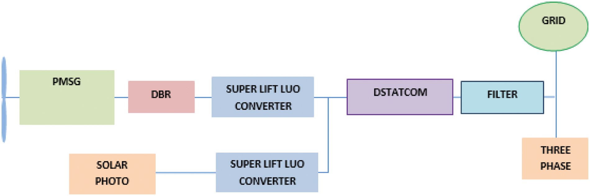
Figure 1: Block diagram of the proposed hybrid energy harvesting system
The wind turbine demands a MPPT system to ensure the maximum harvest of wind energy for the prevailing wind velocity. Similarly, the PV system requires MPPT, to maximize energy harvested for a given solar irradiation and temperature. The proposed system has employed Hill Climbing method and SMC to maintain MPPT in WECS and SPV system respectively.
The DSTATCOM, performs the integration of energy harvested from renewable energy sources and extends reactive power support to the system. During the operation of DSTATCOM, DC link voltage and DC component of three-phase voltage at Power Control Centre (PCC) are regulated by using two different Proportional-Integral (PI) controllers, which have been tuned by Gravitational Search Algorithm.
3 Solar Photo Voltaic (PV) Subsystem
The proposed hybrid energy harvesting system uses wind and PV source. The PV source has been processed by SLLC and harvested energy reaches the DC link of DSTATCOM. The specifications of solar PV system are shown in Tab. 1
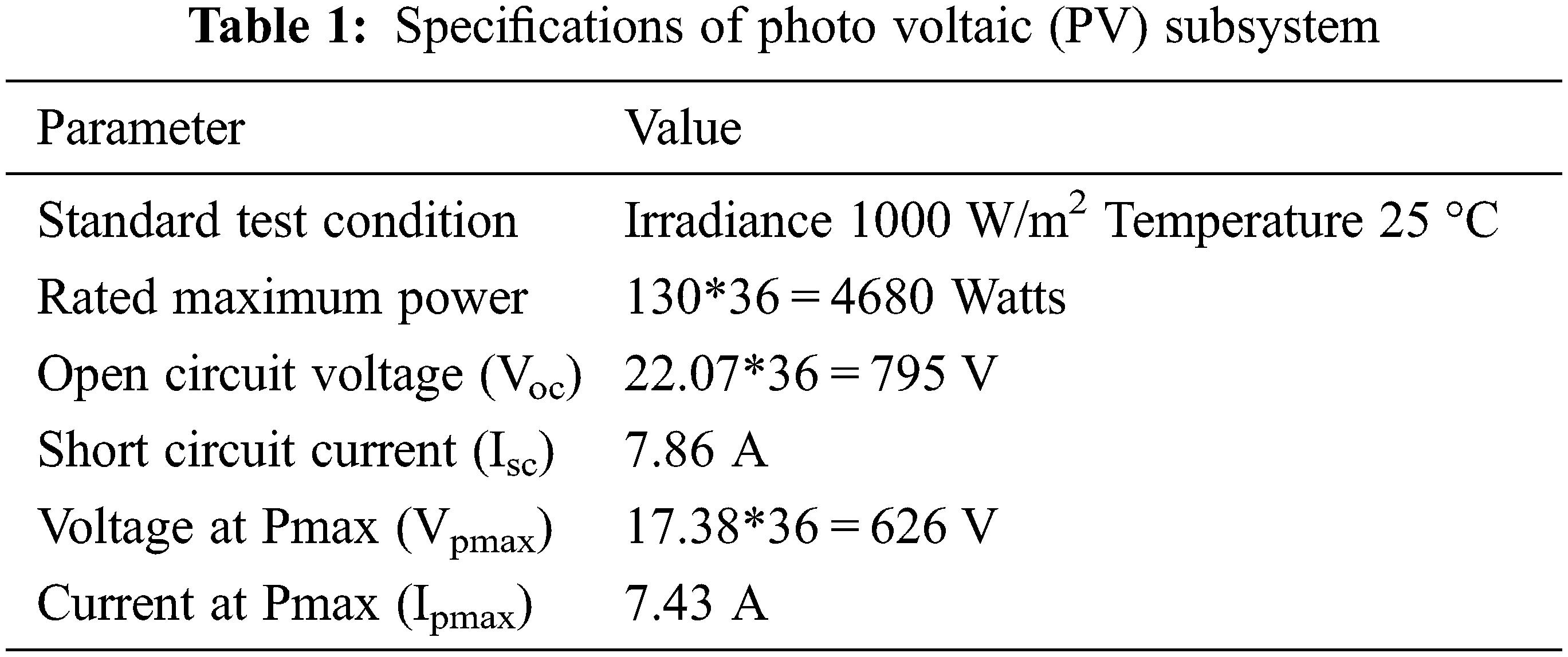
The Voltage - Current (VI) and Power - Voltage (PV) characteristics of a single SPV panel for which the maximum power is 130 Watts and the total terminal voltage is 626 Volts, when 36 panels are connected in series. The SMC-based MPPT ensures the maximum power harvest for given solar irradiation and temperature. Unlike Perturb and Observe and Incremental Conductance method of MPPT, SMC based MPPT control requires voltage across the PV panel only, which is shown in Figs. 2a and 2b.
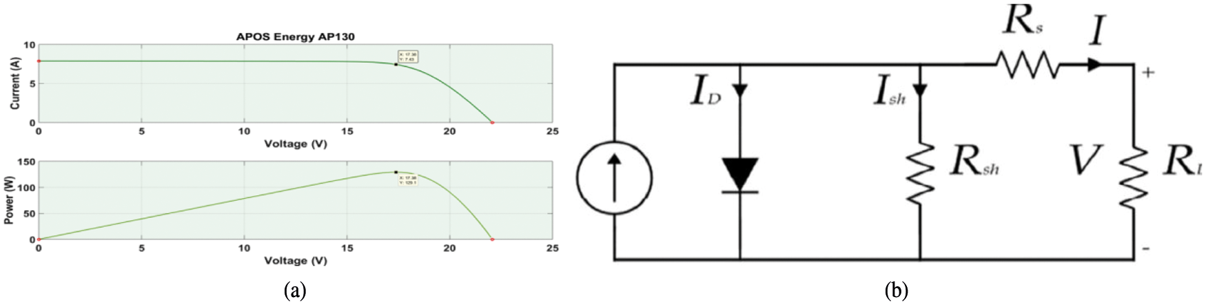
Figure 2: (a) Voltage–current (VI) and power–voltage (PV) curve of photovoltaic (PV) panel. (b) Single diode model of PV cell
The single diode model of a PV cell is given in Eq. (1).
where, IL is output or load current, V is output voltage, Io is reverse saturation current, Rs is equivalent series resistance and Rsh is equivalent shunt resistance. K is Boltzmann’s constant, T is absolute temperature and q is charge.
4 Super Lift Luo Converter (SLLC)
The SLLC is a DC to DC converter, which has been used to lift the DC voltage level available across the terminals of the SPV module to the level of prevailing DC link voltage of DSTATCOM. The SLLC is a single switched DC to DC converter with more number of storage elements and diodes, which is an improved version of basic lift type DC to DC boost converter. The source and load currents of SLLC are usually continuous. The topology of SLLC is shown in Fig. 3.
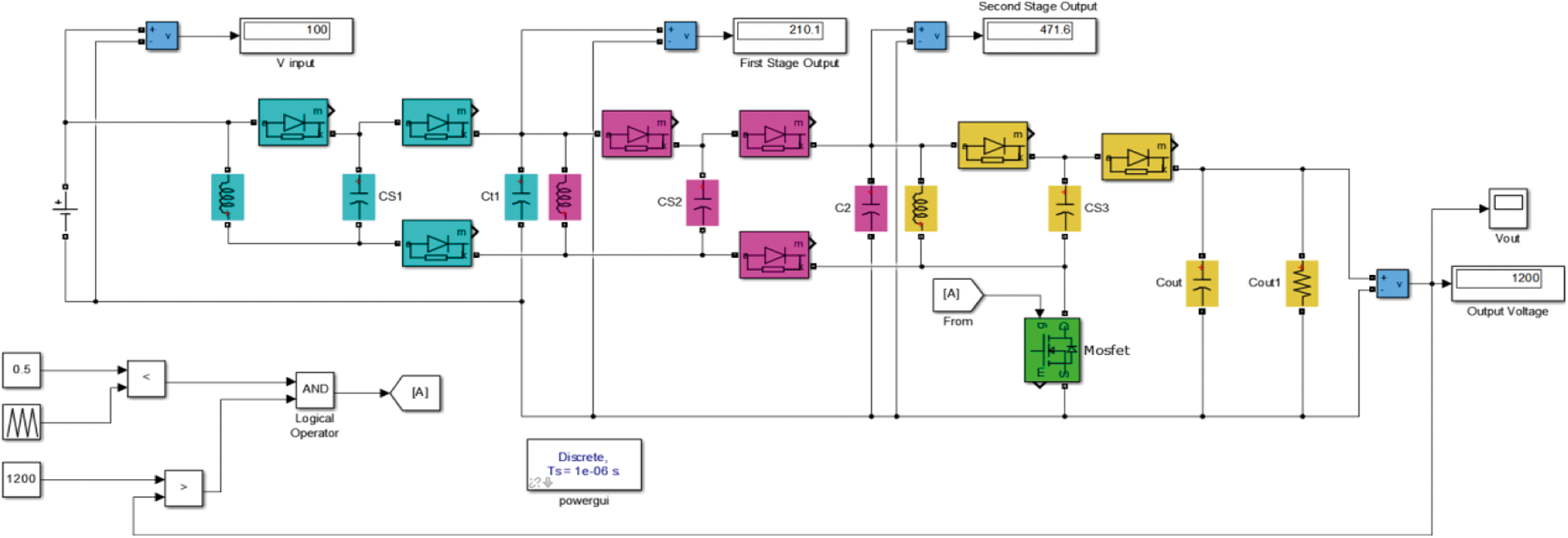
Figure 3: The topology of super lift luo converter (SLLC)
The SLLC is using only one power electronic switch, which is capable of providing a large voltage gain, reduce the control complexity and switching losses. However, the increase in number of storage elements increases the order of the system and becomes highly nonlinear.
The evolution of SLLC starts from basic or elementary lift converter, and its voltage gain is given by the Eq. (2).
The performance of lift technique has been enhanced by cascading single relift stage, and three relift stage voltage gain is given by Eq. (3) and the voltage gain of three stage SLLC is given by Eq. (4).
5 The Permanent Magnet Synchronous Generator (PMSG)
The PMSG is a three-phase synchronous generator which uses permanent magnet pole pairs to produce magnetic flux. The shaft of PMSG is rotated by the wind turbine and generate the Electro Motive Force (EMF), which is a function of the number of pole pairs and speed of PMSG. The frequency of AC output voltage is calculated by using Eq. (5).
In general, unlike SCIG or DFIG, the PMSG based WECS do not use gear box. The speed of PMSG and the turbine, which has made the PMSG to run slowly as compared to SCIG. The PMSG has a large number of pole are the same pairs, that led to reach the generated EMF frequency from 20 to 70 Hz. The three-phase output of PMSG may be terminated across a passive three phase DBR or a three-phase active rectifier. The complete energy harvested passes through power electronic converter and hence PMSG based WECS comes under full scale conversion system. In this proposd system, the output of PMSG is terminated across a DBR and DC output voltage of DBR is stepped up using SLLC. The SLLC delivers power at the DC link of DSTATCOM, which injects power into the grid through an Resistor – Inductor (RL) filter.
5.1 Maxmum Power Point Tracking (MPPT) Applied to Wind Energy Conversion System (WECS)
The WECS is a renewable energy harvesting system and its preformance depends upon environmental conditions particularly the wind velocity. The maximum power is harvested, when the wind turbine has been rotated at a particular speed for a given wind velocity. The shaft speed should be adjusted in such a manner that power generation is maximum for a new wind velocity.
The block diagram of WECS is shown in Fig. 4, where wind turbine drives PMSG and electrical power generated by PMSG is in the form of AC three phase with a frequency corresponding to the number of poles and speed of PMSG. The three phase AC power is converted into DC form by DBR and the DC voltage output of DBR is stepped up by SLLC to attain the voltage level acceptable at the DC link of DSTATCOM. The power conversion occurs between the DC link of DSTATCOM and PMSG. The SLLC is the power control sub system, which controls the output power of SLLC delivered to DSTATCOM, for achieving the MPPT. In the proposed system, power delivered to DSTATCOM is calculated by measuring the voltage across output of SLLC and current flows into DSTATCOM. The Hill climbing algorithm ensures the maximum power harvest, by adjusting the manipulated variable ‘D’, which is the duty cycle of SLLC, and Power ‘P’ delivered to DSTATCOM.
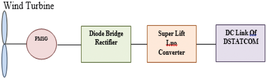
Figure 4: The wind energy conversion system (WECS) channel
The flow chart of hill climbing type of MPPT for PMSG based WECS implemented in SLLC in the power conversion chain, which is shown in Fig. 5. To start with, the duty cycle is initialized with a value ‘D’, then run the converter for measuring the V and I across the DC output terminals of SLLC and the power fed to DC link of DSTATCOM. The duty cycle is adjusted based on the rise or fall of the power being delivered to DSTATCOM. The particular method of including MPPT across the output of SLLC, takes care of non-linearity in the wind turbine and SLLC.
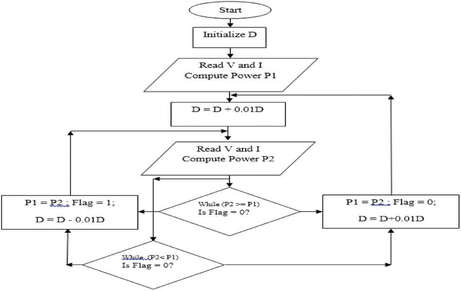
Figure 5: Flow chart of hill climbing maximum power point tracking (MPPT) for WECS
6 Design and Development of the Proposed System
In this method, the harvested renewable energy from SPV and WECS sub system are brought to the DC side of DSTATCOM, which has employed two PI controllers, to promote real and reactive power transaction. The reactive power demand of the load is met by DSTATCOM, and real power is harvested from renewable sources and supplement real power source drawn from grid. If P is the total real power demand of load then the real power supplied by a grid is denoted as PG and the real power supplied by renewable energy channels is denoted by PH , which is related by the Eq. (6).
The complete reactive power demand of load is supplied by DSTATCOM and reactive power supplied by grid is made closer to zero and power factor on the grid side has made closer to unity.
The topological structure of DSTATCOM with series RL filter, connected to PCC is shown in Fig. 6. The control sub system consists of two PI controllers, which produces reference signal, and switching pulses are produced by the sinusoidal Pulse Width Modulation (PWM) section, that uses three phase reference signal.
The PMSG based WECS simulation model is shown in Fig. 7.

Figure 6: Common distributed static synchronous compensator (DSTATCOM), resistor–inductor (RL) filter and control sub systems
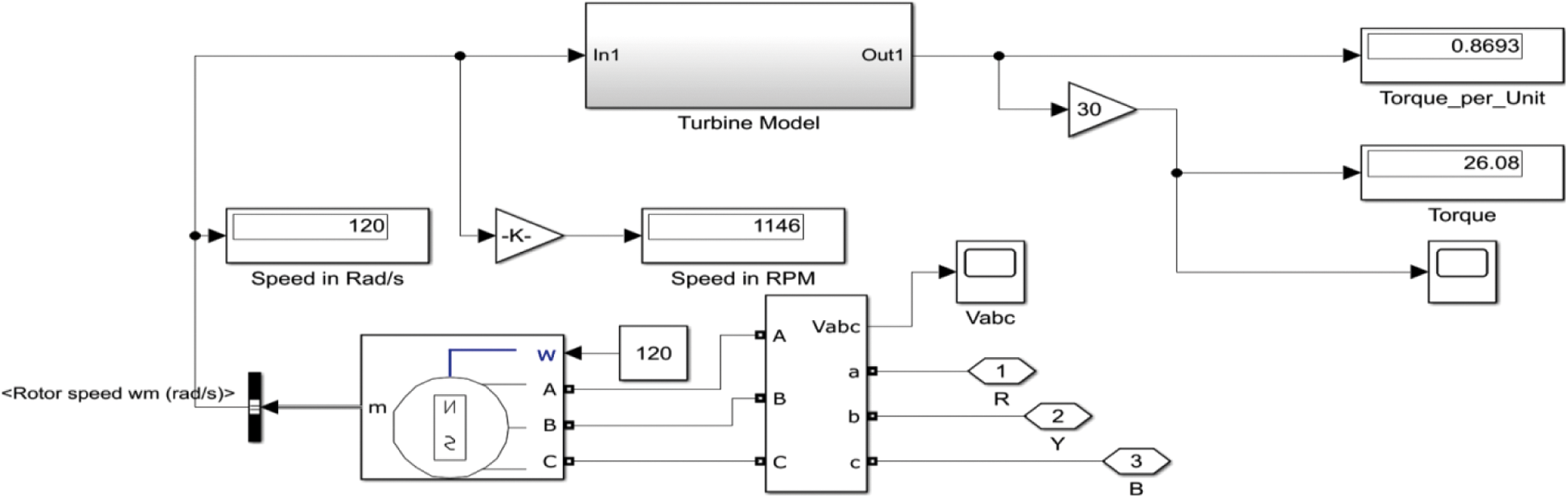
Figure 7: Simulink realization of permanent magnet synchronous generator (PMSG) based WECS
The topology of SLLC is the basic lift type converter with parallel charge and series discharge modules consisting of an inductor and a capacitor. Several such modules can be cascaded to increase the overall DC voltage gain. The voltage gain of a single parallel charge series discharge module is given by (2-D)/(1-D). For a given input voltage, with duty cycle D = 0.5, the voltage gain is 3. If n such modules are cascaded then the overall voltage gain become ((2-D)/(1-D)) n . Therefore, in a three stage SLLC, for a duty cycle D = 0.5, the overall voltage becomes 3*3 = 9, 9*3 V = 27 Volts. A given input voltage of 48 volts and for a duty cycle D = 0.5 then Vout = 1296. The SLLC is capable of stepping up the output DC voltage of solar PV panel and matches it to DC link voltage of DSTATCOM, which is held at 1200 V.
The energy harvested by the WECS is integrated into grid through the DC link of DSTATCOM and controllers associated with it injects an appropriate quantity of real and reactive power into the grid. The proposed system has employed two PI controllers, out of which the first PI controller produces the amplitude component of a reference signal, this controller considers the error between setpoint and actual value of the ‘d’ component of a three-phase AC voltage at PCC.
The second PI controller produces the phase angle of three-phase reference signal, which considers the error between setpoint and actual value of DC-link voltage. The line synchronization is carried out by ‘sin’ and ‘cos’ components and frequency has been detected by Phase-Locked Loop. The subsystem has produced the reference signal after the determination of amplitude and phase components. The basic equation of the three phase reference signal has been given by Eqs. (7) to (9).
7.1 Direct Current (DC) Link Voltage
The DC link voltage of a DSTATCOM is maintained at nearly three times the Root Mean Square (RMS) value of AC line voltage, which is 380 V when the DC link voltage is maintained at 1200 V. The initial DC link voltage is zero, when the system is being commissioned. The DC link has drawn the required 1200 V from 0 V, when renewable energy sources are not connected to DC link and the trajectory of DC link voltage rising from 0 to 1200 V is shown in Fig. 8. The desired voltage level is reached in 0.46 s with an overshoot of 18 V and with a steady state error of 13 V. When the system is initialized in the absence of load and renewable sources, the DC link capacitor is charged from AC mains and rises exponentially till reach 1200 V level.
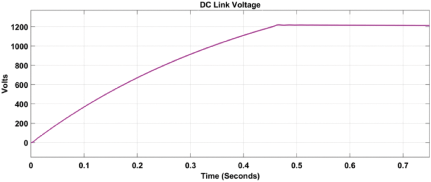
Figure 8: Rise of voltage across direct current (DC) link capacitor
The real power drawn from source is high until the capacitor gets charged is shown in Fig. 9. Once the capacitor reaches the 1200 V level, the power drawn from AC mains is reduced and beyond 0.46 s the power drawn from source may get changed from 20 KW to 100 W, which is used for meeting the losses in DSTATCOM and in series RL filter.

Figure 9: Power transaction waveforms with no load and DC link capacitor charged from grid
The waveforms associated with PV energy harvesting subsystem are presented in this section. Different cases of changes in solar irradiance have been observed. In the first case, the initial solar irradiance has been kept at 0 w/m2, and at time instant 0.5 the irradiance is changed to 1000 w/m2. The initial solar irradiance has been kept at 1000 w/m2 and at time instant 0.5 the irradiance is changed to 500 w/m2. The PV system used in this proposed work have connected 36 panels in series, and the terminal voltage of the panels when the solar irradiance is 1000 w/m2 is 17.38, making the overall terminal voltage as 36*17.38 = 625.68 V. As per the characteristics of a PV panel, the terminal voltage that ensures maximum power harvest when solar irradiance is 500 w/m2 is 617.1 V.
The SLLC interfaces PV sub-system and DC link of DSTATCOM, which is maintained at a constant voltage level of 1200 volts. The SLLC drives a current across the fixed voltage. The real power, pumped into the DC link of DSTATCOM depends on solar irradiance, temperature and variations in the power pumped are manifested in the form of variations in DC link current.
7.3 Wind Energy Harvesting Subsystem
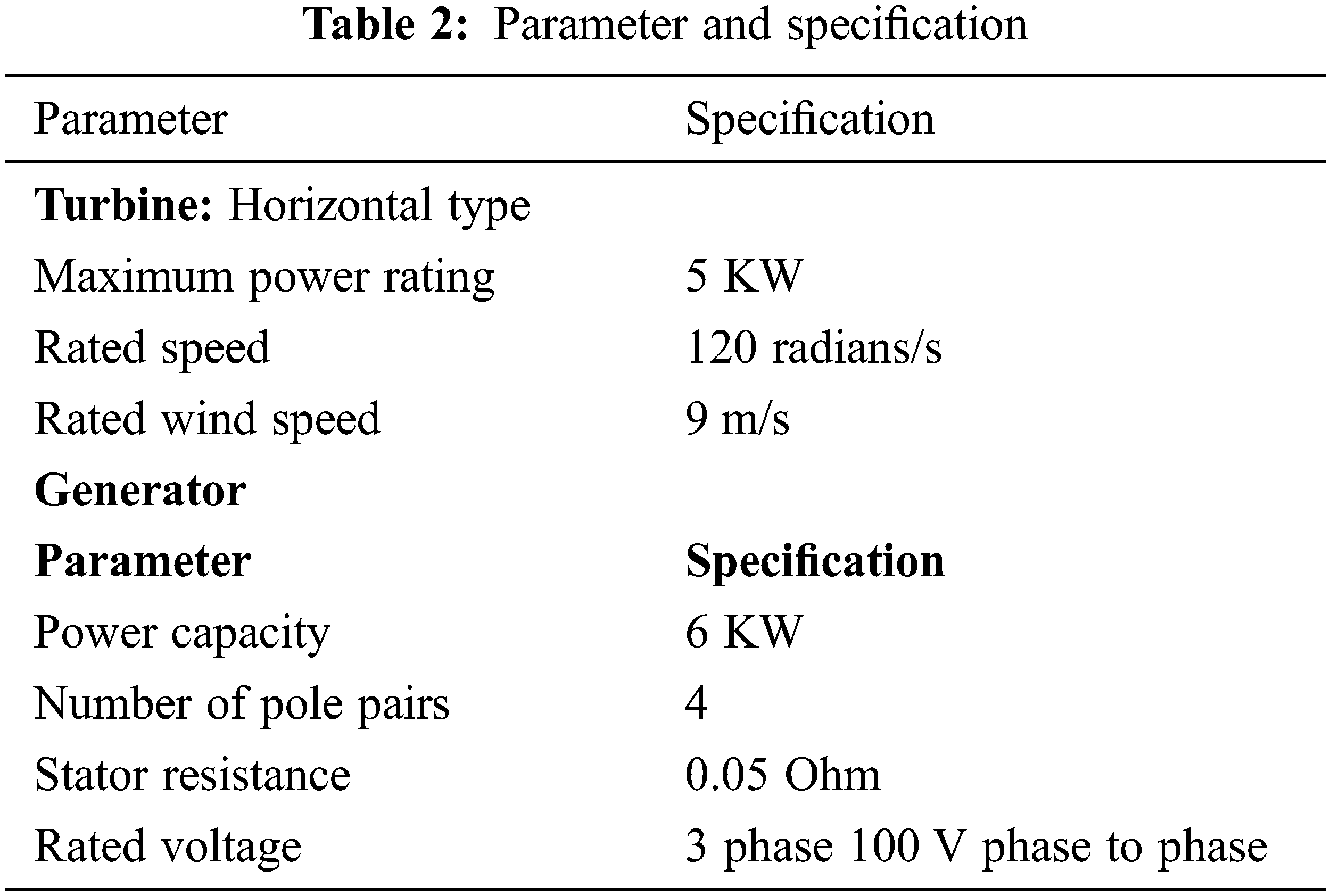
The proposed hybrid renewable energy harvesting system combines wind energy source with PV source is shown in Fig. 10, WECS uses a horizontal wind turbine, which has been coupled with PMSG directly. The PMSG is slow speed machine with large number of magnetic poles. The mechanical linkage between turbine and generator does not use a gearbox. The amplitude and frequency of three-phase AC output voltage of PMSG is a function of speed, which is represented by the equation F = PN/120, where F is the frequency of AC output voltage for the number of poles P and speed N in RPM. The magnitude of AC output voltage output of a PMSG is calculated by using the equation V α 4.44 F Z. The specification of the turbine and generator is given in the Tab. 2.
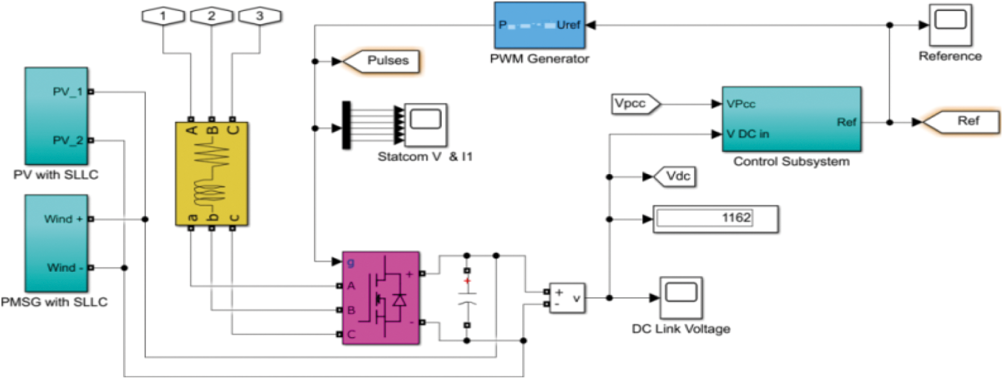
Figure 10: Realization of the complete hybrid energy harvesting and grid integrating subsystems
In both cases, the harvested renewable energy is in DC form and augmented into the grid through the DC link of a DSTATCOM, that is connected to PCC of grid. The DSTATCOM provides continuous reactive power support while renewable energy sources are available, and real power support is also extended.
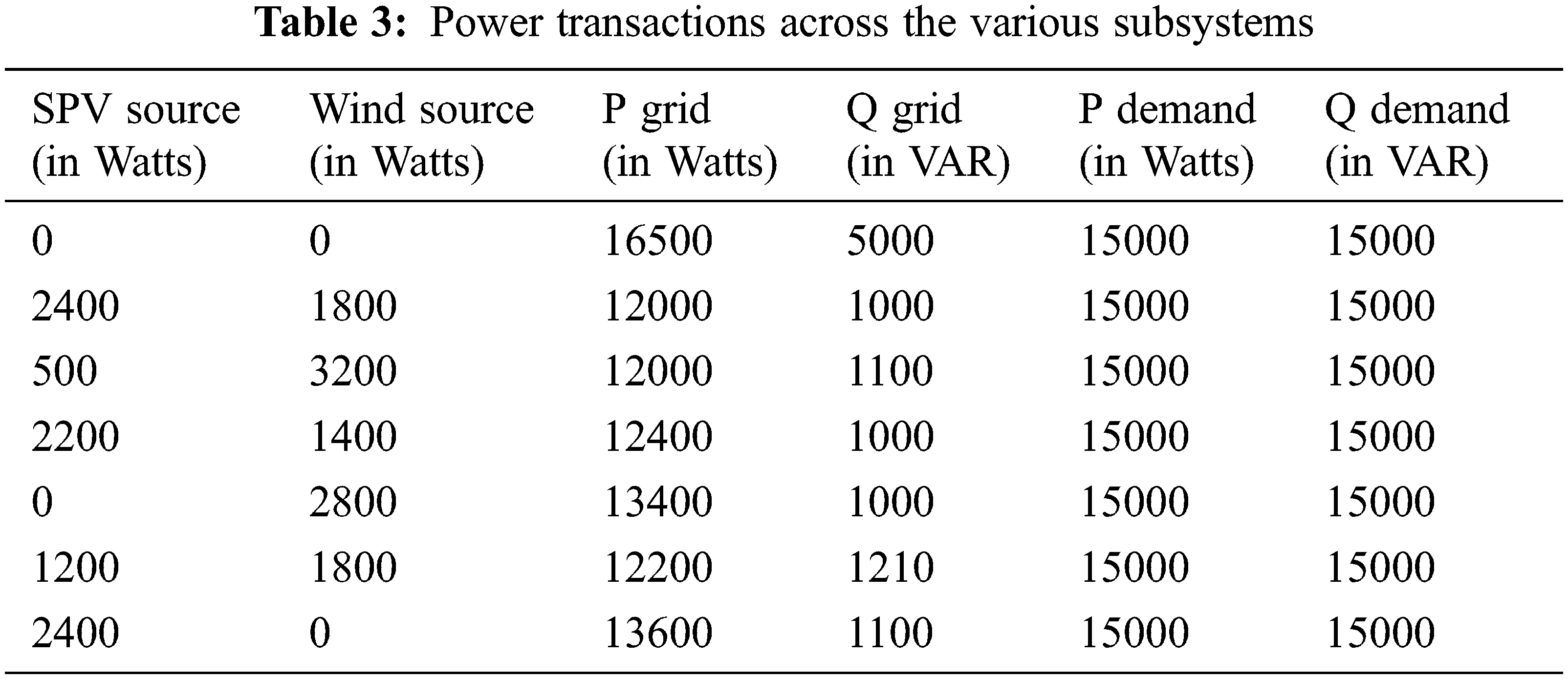
For the Solar Photo Voltaic channel, SLLC has been used between the terminals of the SPV panel subsystem and the DC link of the DSTATCOM. This is necessary for matching the existing higher voltage level across the DC link of DSTATCOM and relative lower voltage prevailing across the output terminals of a PV subsystem. Some important results are consolidated and presented in this section. The power transactions across the various subsystems of SPV, PMSG and WECS based hybrid energy harvesting and grid integration systems are given in Tab. 3.
The proposed method integrates the hybrid arrangement of solar and wind energy harvesting system with a grid, analyzed its performance and validated. The DC link of a DSTATCOM has been employed to integrate the harvested renewable energy from SPV and WECS to the grid, and also provided an additional reactive power support to the system. The solar PV channel with SLLC has been used to lift the voltage at the desired level. The PMSG has used DBR with SLLC to keep the same polarity regardless of the polarities of input AC signal. This research work integrates PV source with a wind energy source through two different combinations. In first combination PV source has been integrated with SCIG and in second case PV source has been combined with PMSG based WECS for energy harvesting. The performance of the proposed method has been analyzed by using MATLAB Simulink model.
Funding Statement: The authors received no specific funding for this study.
Conflicts of Interest: The authors declare that they have no conflicts of interest to report regarding the present study.
Reference
1. V. Khare, S. Nema and P. Baredar, “Solar–wind hybrid renewable energy system: A review,” Renewable and Sustainable Energy Reviews, vol. 58, no. 1, pp. 23–33, 2016. [Google Scholar]
2. I. B. Kyari and J. Y. Muhammad, “Hybrid renewable energy systems for electrification,” A Review Science Journal of Circuits, Systems and Signal Processing, vol. 8, no. 2, pp. 32–39, 2019. [Google Scholar]
3. Y. Sawle, S. C. Gupta and A. K. Bohre, “Pv wind hybrid system: A review with case study,” Cogent Engineering, vol. 3, no. 1, pp. 1–31, 2016. [Google Scholar]
4. P. Ganguly, A. Kalam and A. Zayegh, “Hybrid-renewable energy systems in micro grids, integration, developments and control,” Wood Head Publishing Series in Energy, vol. 1, no. 1, pp. 219–248, 2018. [Google Scholar]
5. A. Imran, G. Hafeez, I. Khan, M. Usman, Z. Shafiq et al., “Heuristic-based programmable control for efficient energy management under renewable energy sources and energy storage system in smart grid,” IEEE Access, vol. 8, no. 1, pp. 139587–139608, 2020. [Google Scholar]
6. E. M. Molla and C. C. Kuo, “Voltage sag enhancement of grid connected hybrid pv-wind power system using battery and smes based dynamic voltage restorer,” IEEE Access, vol. 8, no. 1, pp. 96528–96542, 2020. [Google Scholar]
7. A. A. A. Radwan and Y. A. R. I. Mohamed, “Grid-connected wind-solar cogeneration using back-to-back voltage-source converters,” IEEE Transactions on Sustainable Energy, vol. 11, no. 1, pp. 315–325, 2020. [Google Scholar]
8. I. Atawi and S. Zaid, “Model predictive control of h7 transformerless inverter powered by pv,” Intelligent Automation and Soft Computing, vol. 31, no. 1, pp. 449–469, 2022. [Google Scholar]
9. S. M. Radaideh and M. T. Hayajneh, “A new fuzzy gain scheduling scheme for the pid controllers,” Intelligent Automation and Soft Computing, vol. 9, no. 4, pp. 269–277, 2003. [Google Scholar]
10. M. Deepu Vijay, G. Bhuvaneswari and B. Singh, “A reliable microgrid comprising solar pv-wegs and battery with seamless power transfer capability,” IEEE Transactions on Industrial Electronics, vol. 68, no. 10, pp. 9665–9674, 2021. [Google Scholar]
11. S. Kewat and B. Singh, “Grid synchronization of wec-pv-bes based distributed generation system using robust control strategy,” IEEE Transactions on Industry Applications, vol. 56, no. 6, pp. 7088–7098, 2020. [Google Scholar]
12. N. Kumar, T. K. Saha and D. Jayati, “Multilevel inverter (mli)-based stand-alone photovoltaic system: Modeling, analysis and control,” IEEE Systems Journal, vol. 14, no. 1, pp. 909–915, 2020. [Google Scholar]
13. N. Kumar, T. K. Saha and D. Jayati, “Control, implementation, and analysis of a dual two-level photovoltaic inverter based on modified proportional–resonant controller,” IET Renewable Power Generation, vol. 12, no. 5, pp. 598–604, 2018. [Google Scholar]
14. M. Trifkovic, M. Sheikhzadeh, K. Nigim and P. Daoutidis, “Modeling and control of a renewable hybrid energy system with hydrogen storage,” IEEE Transactions on Control Systems Technology, vol. 22, no. 1, pp. 169–179, 2014. [Google Scholar]
15. M. Manohar, E. Koley and S. Ghosh, “Stochastic weather modeling-based protection scheme for hybrid pv–wind system with immunity against solar irradiance and wind speed,” IEEE Systems Journal, vol. 14, no. 3, pp. 3430–3439, 2020. [Google Scholar]
16. P. Satish Kumar, R. P. S. Chandrasena, V. Ramu, G. N. Srinivas and K. Victor Sam Moses Babu, “Energy management system for small scale hybrid wind solar battery based microgrid,” IEEE Access, vol. 8, no. 1, pp. 8336–8345, 2020. [Google Scholar]
17. N. Priyadarshi, P. Sanjeevikumar, B. R. Mahajan Sagar, F. Blaabjerg and A. Sharma, “Fuzzy svpwm-based inverter control realisation of grid integrated photovoltaic-wind system with fuzzy particle swarm optimization maximum power point tracking algorithm for a grid-connected pv/wind power generation system: Hardware implementation,” IET Electric Power Applications, vol. 12, no. 7, pp. 962–971, 2018. [Google Scholar]
18. C. Bhattacharjee and B. Krishna Roy, “Advanced fuzzy power extraction control of wind energy conversion system for power quality improvement in a grid tied hybrid generation system,” IET Generation, Transmission and Distribution, vol. 10, no. 5, pp. 1179–1189, 2016. [Google Scholar]
19. P. Veera Manikandan and S. Selvaperumal, “Investigation of different mppt techniques based on fuzzy logic controller for multilevel dc link inverter to solve the partial shading,” Soft Computing, vol. 25, no. 4, pp. 3143–3154, 2021. [Google Scholar]
20. P. García, C. A. García, L. M. Fernández, F. Llorens and F. Jurado, “Anfis-based control of a grid-connected hybrid system integrating renewable energies, hydrogen and batteries,” IEEE Transactions on Industrial Informatics, vol. 10, no. 2, pp. 1107–1117, 2014. [Google Scholar]
21. O. Zarrad, M. A. Hajjaji, A. Jemaa and M. N. Mansouri, “Sizing control and hardware implementation of a hybrid wind-solar power system, based on an ann approach, for pumping water,” Hindawi International Journal of Photo Energy, vol. 1, no. 1, pp. 1–15, 2019. [Google Scholar]
22. M. Ali and M. Nejib, “Hardware implementation of hybrid wind-solar energy system for pumping water based on artificial neural network controller,” Studies in Informatics and Control, vol. 28, no. 1, pp. 35–44, 2019. [Google Scholar]
 | This work is licensed under a Creative Commons Attribution 4.0 International License, which permits unrestricted use, distribution, and reproduction in any medium, provided the original work is properly cited. |