DOI:10.32604/iasc.2022.026032
| Intelligent Automation & Soft Computing DOI:10.32604/iasc.2022.026032 | |
| Article |
Energy Management of an Isolated Wind/Photovoltaic Microgrid Using Cuckoo Search Algorithm
1Department of Electrical Engineering, Faculty of Engineering, University of Tabuk, Tabuk, 47913, Saudi Arabia
2Department of Electrical Engineering, Faculty of Engineering, Sohag University, Sohag, Egypt
3Renewable Energy and Energy Efficiency Centre (REEEC), University of Tabuk, Tabuk, 47913, Saudi Arabia
4Department of Electrical Power, Faculty of Engineering, Cairo University, Cairo, 12613, Egypt
5Department of Civil Engineering, Faculty of Engineering, University of Tabuk, Tabuk, 47913, Saudi Arabia
6Sensor Networks and Cellular System Research Centre, University of Tabuk, Saudi Arabia
*Corresponding Author: Sherif A. Zaid. Email: shfaraj@ut.edu.sa
Received: 13 December 2021; Accepted: 21 February 2022
Abstract: This paper introduces a renewable-energy-based microgrid that includes Photovoltaic (PV) energy and wind energy generation units. Also, an energy storage system is present. The proposed microgrid is loaded with a constant load impedance. To improve the performance of the proposed microgrid, an optimal control algorithm utilizing Cuckoo Search Algorithm (CSA) is adapted. It has many merits such as fast convergence, simple tunning, and high efficiency. Commonly, the PV and wind energies are suitable for supplying loads under normal conditions. However, the energy storage system recovers the excess load demand. The load frequency and voltage are regulated using the CSA optimal controller. The microgrid responses with the introduced optimal controller are measured under step changes in load demand, wind power, and the PV irradiation level. Matlab simulations are carried out to test the proposed system performance. The simulation results showed that the proposed microgrid fed the load with Alternating Current (AC) power of constant amplitude and frequency for all disturbances. Moreover, the required load demand has been perfectly compensated. Moreover, the performance of the storage system is excellent with the unstable wind speed and variable solar irradiation. Also, the results with the optimal CSA controller are compared to those with the Particle Swarm Optimization (PSO) algorithm at the same conditions. It is also found that the optimal CSA controller provides better responses.
Keywords: Cuckoo search algorithm; wind energy; photovoltaic energy; microgrid
Due to the growing electricity demand, renewable energy sources have become significantly important nowadays. Relying on fossil fuels for energy production increased environmental concerns to use alternative clean energy sources. Therefore, solar and wind energy sources are considered a viable choice for clean energy production in the future. Despite being emission-free solar and wind energy sources are available at no cost. Moreover, they can deliver power to remote areas that are not accessible by the electricity companies or not connected to the grid. Also, they can offer a solution for countries that are suffering a shortage of fossil fuel energies [1]. However, these sources are weather-dependent and have an intermittence nature. Hence, unpredictability and fluctuations of power production present a challenge to the power system when utilizing these resources [2]. However, the integration of sustainable energy sources is very important for the stability of the utility grid and standalone applications. Hence, the use of Energy Storage Systems (ESS) provides an excellent solution to the intermittence problem. Therefore, to provide an efficient and smooth power transfer hybrid energy systems with ESS are highly recommended [3]. Thus, microgrids are considered as a key concept to incorporate distributed and renewable energy sources along with ESS.
The development of the microgrids concept is vital to deal with renewable energy penetration nowadays. It has the facility that the final user can store, control, generate, and manage a portion of the consumed energy, which makes the customers be a part of the grid and not only a consumer [4]. Many advantages are gained from microgrids for both utilities and consumers. Microgrids concept helps to reduce power flow on transmission and distribution lines, minimize power losses, and decrease the cost for extra power sources. Furthermore, microgrids can decrease the load demand on the electricity grid and help to reduce the emissions that threaten climate change [5–7]. Also, it can assist and repair the network in case of faults.
Various types of microgrids have been explored in the literature. However, hybrid wind/PV microgrids are commonly utilized. Authors in [8] introduced wind/PV hybrid microgrid controlled by fuzzy and ensure maximum power conditions. The control objectives were decreasing the battery storage needed and regulating the load energy. Nevertheless, the microgrid control was complex. New energy management and control of a hybrid wind-PV-battery microgrid with storage are described in [9]. The authors provide an experimental verification, but the power was small. A dynamic modeling and operation scheme of a wind/solar hybrid power system is presented in [10] with a multiple-input converter. Authors in [11] proposed a microgrid that is powered by two renewable energy sources, namely wind energy using a doubly-fed induction generator and PV array in addition to a diesel generator. The control system is designed to optimize the fuel consumption of the diesel generator and extract maximum power from both wind and PV. However, the load power had low quality and the current was distorted. A grid-connected microgrid utilizing wind-solar cogeneration based on back-to-back converters is introduced in [12]. Nevertheless, the system has slightly lower efficiency. In [13], proposes a hybrid wind/PV microgrid along with a battery energy storage to supply utility grid feeding the nonlinear load. The power quality improvement and nonlinear load compensation have been reached using a modified adaptive filtering technique. A new control technique to smooth the fluctuations of the output power for a hybrid wind/PV and regulate the battery state of charge has been proposed by [14]. However, the control system was complex and expensive.
The control scheme of the microgrid can be classified based on the modes of operation into grid-connected and isolated modes [15]. The general objective of this control scheme is to regulate the voltage and frequency of the microgrid. Moreover, it must maintain stable operation for the microgrid especially when interconnecting with other networks or facing sudden load changes. In grid-connected mode, the host grid dominantly defines the microgrid voltage and frequency at the point of common coupling. Therefore, the main function of the microgrid control system is to adjust the active and reactive power produced by the distributed energy resources. In isolated mode, the microgrid works as an autonomous unit. As a result, more challenges appear in this mode than the grid-connected one, since the critical supply-demand balance needs the execution of exact load sharing mechanisms to balance unexpected active power mismatches. The utility grid is no longer supporting the voltages and frequency of the microgrid.
Many control techniques have been applied to wind/PV microgrids [16]. Recently, optimization techniques have been used to control and improve the response of complicated systems. Nevertheless, evolutionary optimization is rapidly and widely utilized by researchers for tremendous applications [17]. It is considered an integral development of the PSO algorithm. It has the merits of high convergence speed, small memory requirements for computation, and low execution time [18]. Nowadays, a promising search technique is called the cuckoo search algorithm. It has been gotten inspired by the breeding process of the cuckoos [19]. Compared to the PSO, the CSA has to tune a lower number of parameters. Hence, it is widely used in the optimization of complex problems [20]. The authors in [21] have utilized CSA in solving the static power flow problems for the proposed system. It applies the CSA to the capacitor allocation problem in the distribution systems. However, it has been fitted for solving the non-convex economic dispatch of the system in [22]. Lately, the CSA is used to substantially tune the Proportional-Integral-Derivative (PID) controller of a nonlinear for interconnected three area power system [23].
In this paper, an electrical microgrid is optimally controlled and managed using the CSA algorithm. The objectives of this study are enhancing the performance of the wind/PV microgrid, improving energy management, and optimizing the response using the CSA. The introduced microgrid includes an impedance that represents the static load. The sources are solar PV and wind energy systems. Moreover, it contains an ESS, uncontrolled rectifier, and 3-φ inverter.
In normal circumstances, the energy from the PV and wind generation are acclimatized to feed the loads. The excess energy is stored in the ESS during the peak power generation periods. During the generation drop periods, the ESS returns the stored energy to the loads.
From the results, it has been investigated that the proposed renewable microgrid can feed the loads skillfully and manage the stored energy carefully. Additionally, the response of the inverter controller is very precise as it tracks the required load demand perfectly. The major contributions of this work are:
• Developing an analytical model of the proposed wind/PV microgrid that is optimally controlled and managed using the CSA algorithm.
• Improving the energy management of the proposed wind/PV microgrid.
• Optimizing the performance of the proposed wind/PV microgrid using the CSA against disturbances in the load power, wind speed, and solar insolation.
• The responses of the system with CSA are compared to that with the PSO.
The manuscript is prepared as follows: the structure of the proposed microgrid is included in Section 2. Section 3 investigates the microgrid dynamic model. Section 4 presents the details of the proposed microgrid energy management and control. Section 5 talks about the simulation results. The research conclusions are included in Section 6.
2 The Proposed Microgrid Structure
The proposed, presented in Fig. 1, microgrid incorporates wind/PV energy sources with an ESS system and supplies two independent loads. The wind turbine provides the mechanical energy to a 3-φ Permanent Magnet Synchronous Generator (PMSG). The PMSG generates a 3-φ output voltage that is fed to an uncontrolled rectified forming the Direct Current (DC) link of the grid. The DC link is attached to the PV too. The PV panel is built by connecting series and parallel strings such that the PV terminal voltage is compatible with the DC link voltage level. Usually, a DC capacitor is attached to the PV terminal to provide better performance of the PV. Also, a power diode is connected after the capacitor to protect the PV and the capacitor from severe overvoltage and reverse power. The DC link is linked to ESS batteries through a bidirectional DC/DC converter. The function of that converter is to manage the charge/discharge process of the ESS batteries. On the other hand, this converter provides a way to regulate the DC link voltage level.
The DC link represents the input of the 3-φ inverter that converts the DC voltage into AC voltage with the utility frequency. The inverter output feeds the system loads. The system has a static load that can be represented by an impedance. The objectives of the inverter controller are supplying the load with AC power with constant voltage amplitude and frequency.
Commonly, the wind speed varies from time to time. Hence, the PMSG output power varies as well. As well, the PV-generated power varies from time to time. Hence, the ESS compensates for the power drop for the load if the power generated by the hybrid wind/PV decreases. Therefore, the ESS represents the slave energy source to recompense any decay in the generated energy of the wind/PV. Also, it helps supply additional loads.
An inverter controller is adapted to regulate the inverter frequency and voltage. The variations in the voltage occur frequently due to solar insolation and wind speed variations.
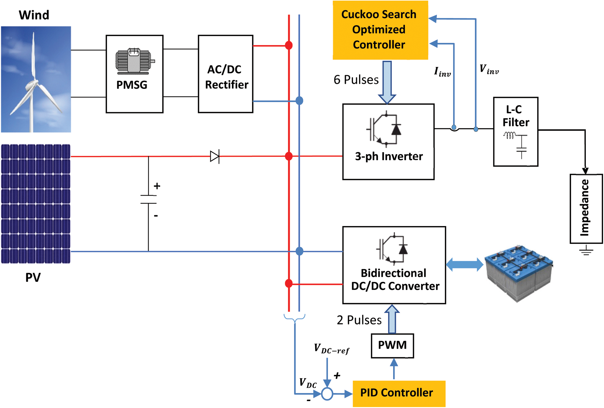
Figure 1: The proposed system block diagram
To realize the design, control, and simulation of the proposed microgrid, modeling the system is commonly the first step. The models’ parameters of the microgrid parts have been chosen to be as close to the practical case. Hence, all possible losses, voltage drops, and snubber circuits have been taken into consideration. The dynamic models of the whole microgrid components are explained in the next paragraphs.
The PV panel contained in the proposed microgrid is established from 18 PV modules. It has 3 series cells and 6 parallel strings. Fig. 2 presents the common and approximately precise model of the PV array. The model parameters are the parallel and series resistances (rp, rsh). However, (Ish) is the PV panel short circuit current.
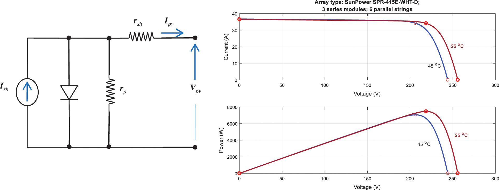
Figure 2: The PV array equivalent circuit model
The function of the turbine is to convert the wind power into rotating mechanical power. A list of symbols used is shown in Tab. 1. The generated mechanical torque (Tm) of the wind turbine is determined by [24]:
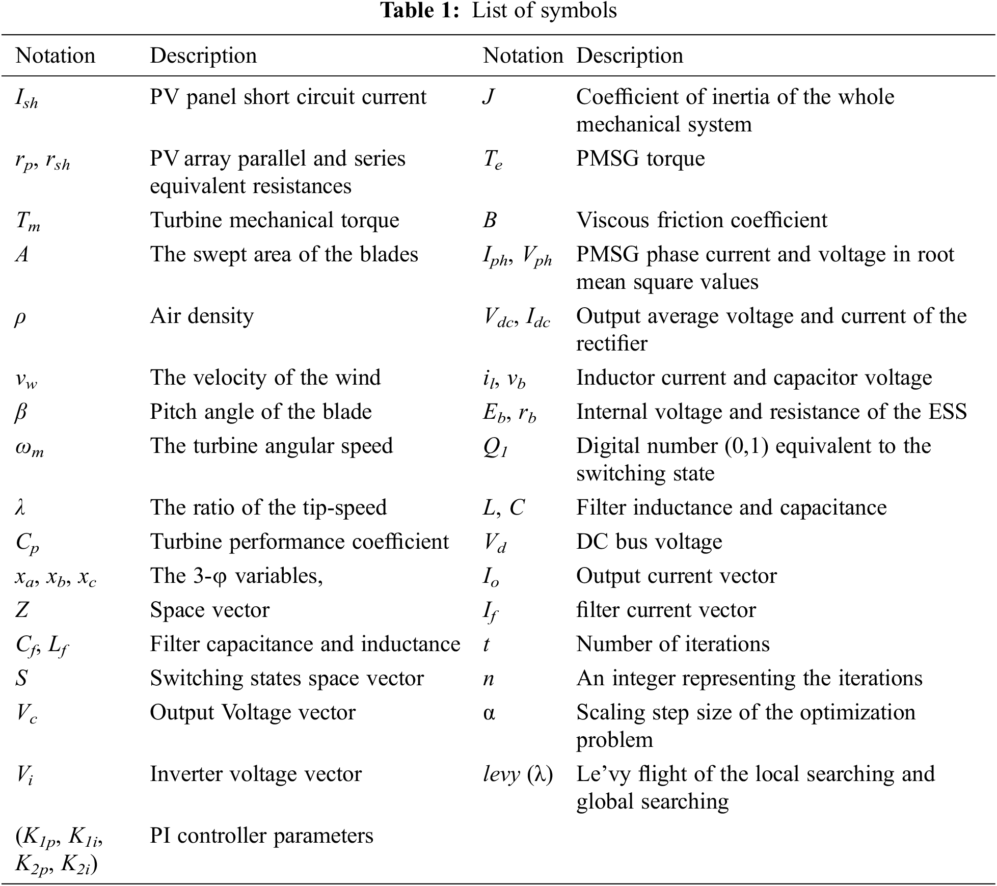
where; (A) is the swept area of the blades; (ρ) is the air density; (vw) is the velocity of the wind; (β) is the pitch angle of the blade; (ωm) is the mechanical angular-speed of the turbine, and λ is the ratio of the tip-speed that is given by :
The turbine performance coefficient (Cp) is given by:
The mechanical system formed by the turbine and the PMSG generator may be modeled by the differential equation:
where; (J) is the coefficient of inertia of the whole system, (Te) is the PMSG torque, and B is the viscous friction coefficient.
It is well known that the PMSG speed is proportional to the wind speed. Nevertheless, the wind speed varies continuously. As the PMSG output voltage and frequency depend mainly on its speed, therefore the PMSG output voltage and frequency are unregulated. However, the electrical loads usually need regulated supplies. To solve this problem, the PMSG output voltage is rectified and connected to the DC bus. Hence, an inverter is used to supply regulated voltage to the loads. An uncontrolled 3-φ rectifier bridge is utilized for this job. The average model of the rectifier is presented by [25]:
where; (Iph, Vph) are the PMSG phase current and voltage in root mean square values and (Vdc, Idc) are the output average voltage and current of the rectifier. The source impedance is neglected,
The ESS is charged/discharged via a two-directional converter shown in Fig. 3. Continuous conduction mode is assumed for this converter. The input of the converter is connected to the DC bus. However, its output is attached to the ESS. The converter has two modes of operation namely the buck/boost modes. When the transistor Q2 is off and the transistor Q1 is switched, this case represents the buck mode. In this case, the ESS is charged. However, it acts in the boost mode when transistor Q1 is off and the transistor Q2 is switched. Therefore, the ESS discharging process is indicated.
The DC/DC converter is modeled as follows:
• The buck mode:
where (il, vb) are the inductor current and capacitor voltage, (Eb, rb) are the internal voltage and resistance of the ESS, Q1 is a digital number (0,1) equivalent to the switching state, (L, C) are the filter inductance and capacitance, and (Vd) is the DC bus voltage.
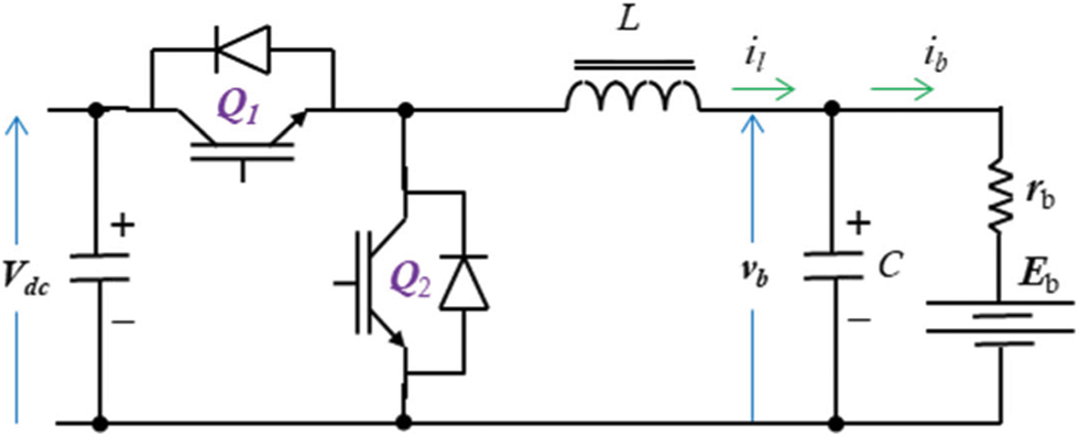
Figure 3: The DC/DC converter circuit
• The boost mode:
where Q2 is a digital number (0,1) equivalent to the switching state.
The 3-φ DC/AC converter circuit diagram incorporating an L-C filter is shown in Fig. 4a. For convenience, all voltages and currents in the circuit have been represented as space vector quantities using:
where; (xa, xb, and xc ) are the 3-φ variables, Z is the space vector, and α = ∠120°.
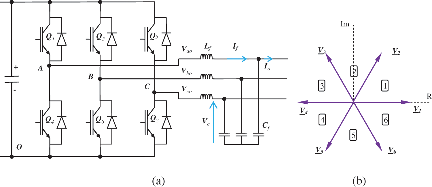
Figure 4: (a) The 3-φ inverter power circuit (b) The 3-φ inverter space vectors
According to the operating rules of the 3-φ inverter, there are 8 switching states. These states can be represented as space vectors shown in Fig. 4b. There are six active voltage vectors and two zero voltage vectors representing the output voltage. The inverter model can be represented by:
where; (Cf, Lf) is the capacitance and inductance of the filter; (S) is the switching states space vector; (Vc) is the voltage of the filter output; (Vi) is the terminal voltage of the inverter; (Io) is the output current; and (If) is and the filter.
4 The Proposed Microgrid Energy Management and Control
Two control loops are forming the control system of the proposed wind/PV microgrid. The DC/DC converter controller which controls the DC bus voltage is the first controller. The DC/AC inverter controller that controls the frequency and voltage of the load is the second controller. The controllers are explained in the next subsections.
4.1 The DC/DC Bidirectional Controller
The function of this controller is to control the ESS charging/discharging processes. Additionally, it regulates the DC bus voltage. A simple Proportional-Integral (PI) controller is assigned for controlling the current and voltage of the ESS using two nested loops, as shown in Fig. 5a. The controller stops charging the ESS batteries when it is fully charged. On the other hand, it provides a small compensating current for the ESS leakage.
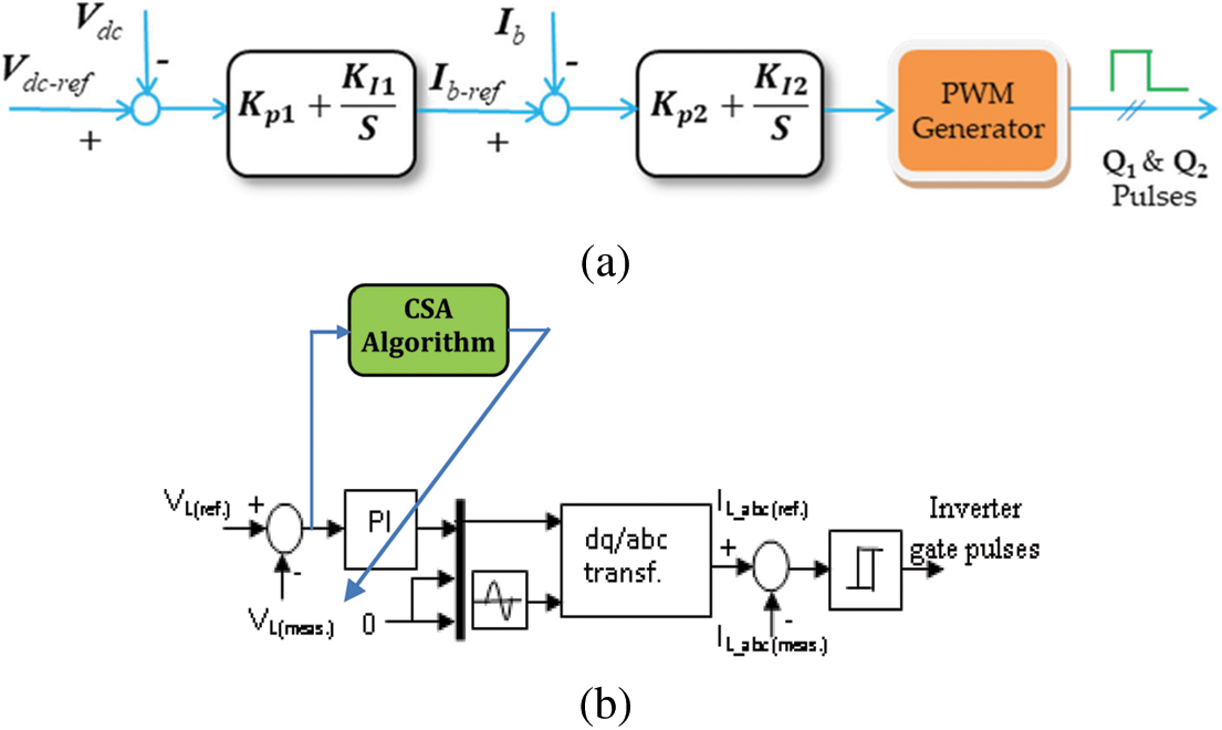
Figure 5: The block diagram of the (a) DC/DC controller (b) DC/AC controller
4.2 The DC/AC Converter Controller
The inverter utilized in the proposed system is a current-controlled voltage source inverter. Hence, the converter has two nested control loops as shown in Fig. 5b. The outer loop is the output voltage loop where the measured output voltage is compared to the reference voltage. The generated error signal is fed to a simple PI controller that generates the reference output current. Nevertheless, the PI parameters are optimized using the CSA. The reference currents are compared to the measured 3-φ currents. Then, the generated error is supplied to a Pulse Width Modulation (PWM) modulator to generate the converter switching signals. The CS optimization technique is explained in the next paragraph.
4.3 The Cuckoo Search Optimization
The CSA optimization concept is derived from the searching process of the Le’vy flight. It has been used to get the optimized solution to many problems. The random walk of the Le’vy flight is divided into steps. It is assumed that the random length of the step has a probability distribution using [26]:
where; (t) is the number of iterations. Eq. (12) indicates that the Le’vy flight has a random walk with a heavy tail.
The main idea of this optimization algorithm is to get the nest that has the optimal solutions. All the nests are considered potential nominees for the optimization. The CSA reproduction process of the cuckoo is based on the following rules [26]:
• Every cuckoo lays an egg in a random nest.
• The optimal solution is produced by the best nest
• The best nest is kept for carrying the next generation of cuckoos.
• The foreign eggs may be discovered by a host bird with a probability (pα).
The new nest of the cuckoos is generated using the global random walk or Le’vy flights:
where (n) is an integer representing the iterations, (α) is the scaling step size of the optimization problem, and (levy (λ)) is Le’vy flight of the local searching and global searching.
An objective function is usually utilized with the CSA algorithm. It helps to test the parameters’ optimization. Many objective functions are introduced in the literature [27], such as; the Integral Time Square Error (ITSE), Integral Square Error (ISE), and Integral Absolute Error (ITAE). However, the ITAE has been commonly used owing to its simplicity and perfect response. Hence, the proposed microgrid uses the ITAE as an objective function:
where; Ts is the sampling time and the PI controllers parameters (K1p, K1i, K2p, K2i) are to be determined with the following constraints:
The optimal CSA controlling parameters of the proposed microgrid are given in Tab. 2. Fig. 6 summarizes the flowchart of the CSA algorithm.
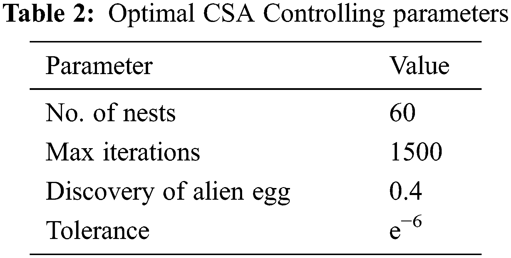
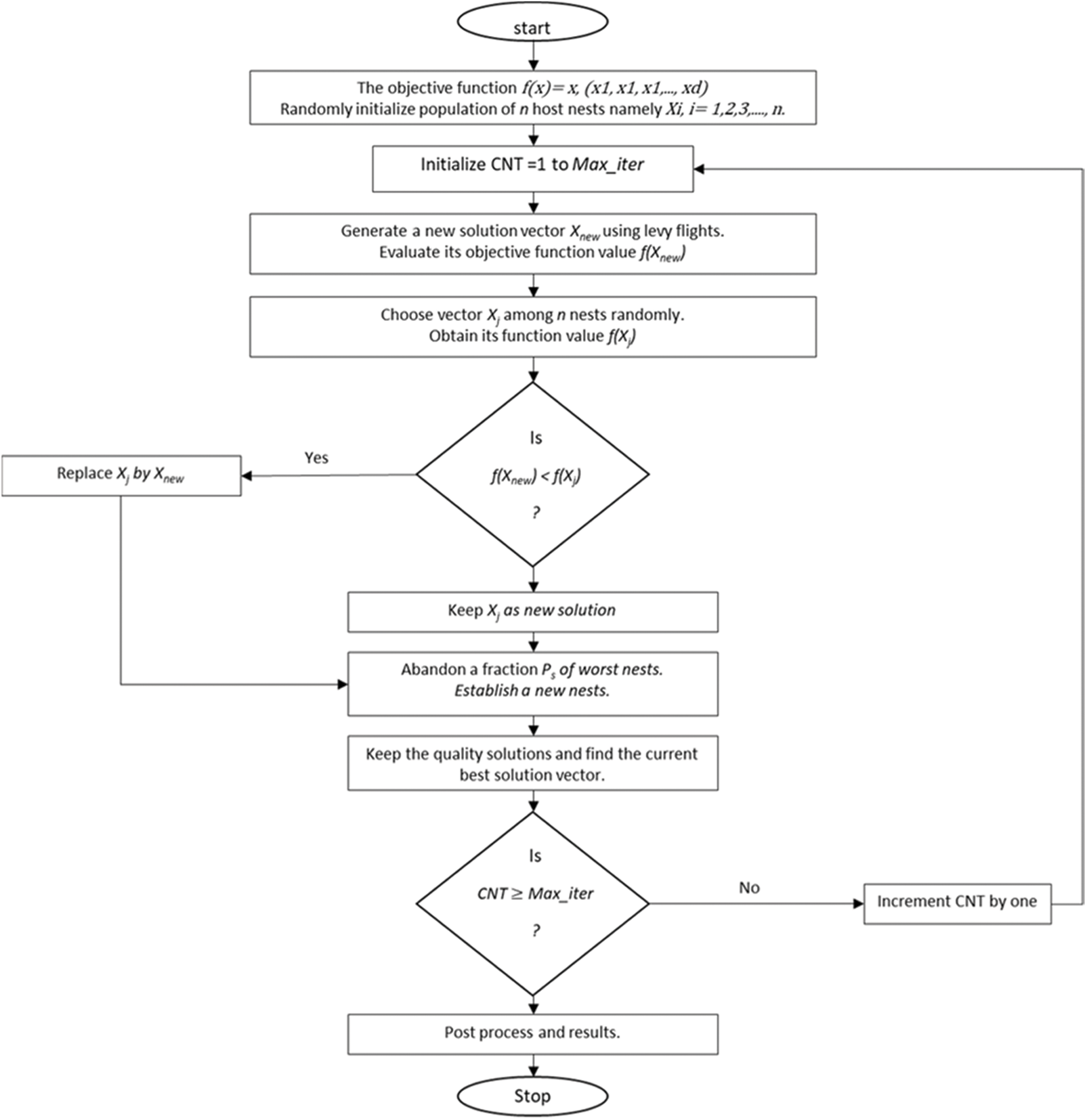
Figure 6: The CSA flowchart
The paper idea is validated using Matlab simulations for the proposed microgrid. The wind turbine and PV-panel parameters are presented in Tab. 3. The system has been tested under step changes in the wind speed and the solar irradiation level, as shown in Fig. 7. Fig. 7a shows the time variation of the wind speed level. The wind speed has kept been kept at 12 m/s until the time 4 s. It has been dropped to 7 m/s, during the period 4 to 5.7 s. The rotor speed of the PMSG is directly related to the wind speed as shown in Fig. 7b. Also, the PMSG torque is negative with a value that depends on the generated power as presented in Fig. 7c. The variation of the solar irradiation level has been presented in Fig. 7d. The irradiation level has step changes at 2 and 5 s. The battery voltage and current are shown in Figs. 7e, 7f. At the period (0 to 2 s), both the PV and the wind energy are full. Therefore, the battery is charged with its voltage increases and its current is positive. At the period (2 to 4 s), the PV energy becomes 40% and the wind energy is full. The total supplied energy is smaller than the load requirement. Hence, the battery starts discharging to compensate for the energy drop. The battery current is negative with its voltage decreasing at this period. At the period (4 to 5 s), the PV energy becomes 40% and the wind speed drops to 7 m/s. The battery continues discharging to compensate for the drop in the supplied energy. Fig. 7g presents the DC-link voltage variations under these disturbances. Nevertheless, it gives a perfect performance as it is nearly stable for all disturbances. The inverter terminal voltage is pulse width modulated that is presented in Fig. 7h. Both the load voltage and current are sinusoidal with constant amplitude and frequency as indicated by Figs. 7i, 7j.
2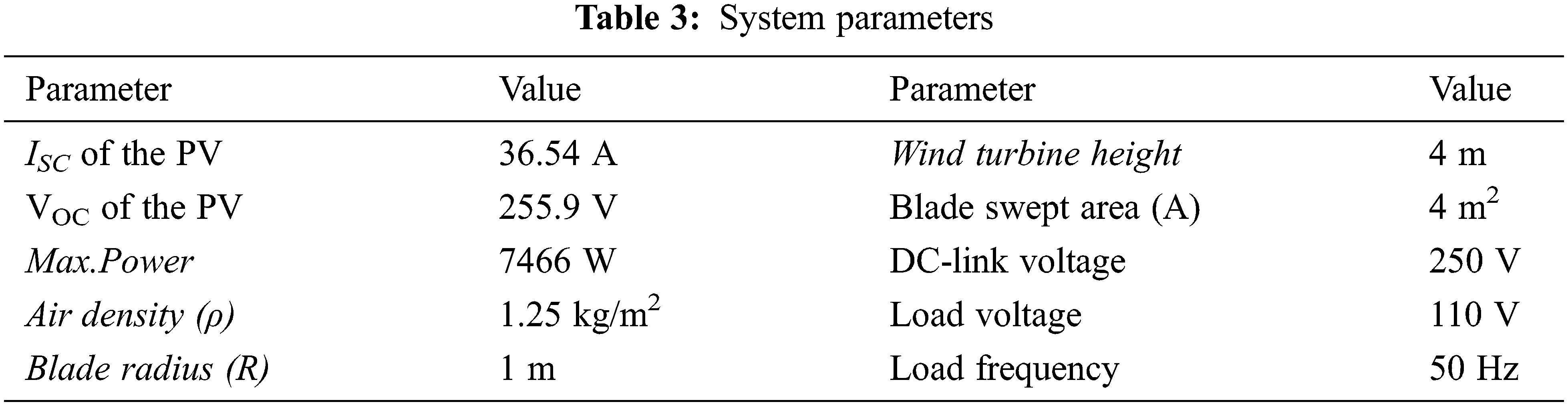
Fig. 8 shows the system responses under step changes in the load in addition to wind and solar energy variations. The time variation of the wind speed level and solar energy irradiation are presented in Figs. 8a and 8d. The wind speed has kept been kept at 12 m/s until the time 4 s. Then it has been dropped to 7 m/s, during the period 4 to 5.7 s. The irradiation level has step changes at 2 and 5 s. The system load is doubled during the period 3 to 4.5 s. The rotor speed of the PMSG is directly related to the wind speed as shown in Fig. 8b. Also, the PMSG torque is negative with a value depending on the generated power as presented in Fig. 8c. Fig. 8e presents the DC-link voltage variations under these disturbances. Nevertheless, it gives a perfect performance as it is nearly stable for all disturbances. The battery current is shown in Fig. 8f. At the period (0 to 2 s), both the PV and the wind energy are full. Therefore, the battery is charged with its voltage increases and its current is positive. At the period (2 to 3 s), the PV energy becomes 40% and the wind energy is full. The total supplied energy is smaller than the load requirement. Hence, the battery starts discharging to compensate for the energy drop. The battery current is negative with its voltage decreasing at this period. During the period (3 to 4 s), the load is doubled in addition to the previous conditions. Hence, the battery discharging current increases to compensate for the load demand. At the period (4 to 4.5 s), the PV energy becomes 40% and the wind speed drops to 7 m/s. The battery continues discharging to compensate for the drop in the supplied energy. The inverter terminal voltage is pulse width modulated that is presented in Fig. 8g. the load voltage is sinusoidal with constant amplitude and frequency for all disturbances, as indicated by Fig. 8h. Fig. 8i presents the inverter modulation index variations. Finally, the load current is presented in Fig. 8j where the current is doubled during the period (3 to 4.5 s).
Since our concerns are also in robust stability against various model uncertainties, some of the system parameters are changed. Where the PV shunt resistance is decreased by 10%, the PV series resistance is increased by 10%, and the wind blade radius is increased by 8%. For the perturbed system, the responses are shown in Fig. 9. It has been indicated in the figure that the proposed controller can stabilize the load voltage and frequency with high accuracy despite the modeling errors.
The response of the system with the proposed CSA approach is compared with the PSO algorithm at the same conditions as shown in Fig. 10. This figure shows that the DC-Link voltage performance in the case of using the CSA algorithm is better than in the case of using the PSO algorithm.
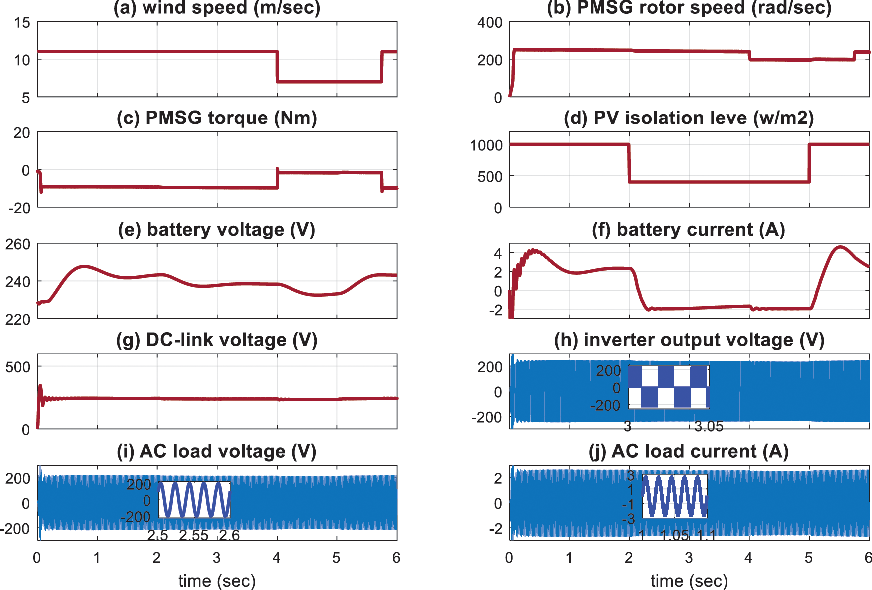
Figure 7: The simulation results with step-change in the wind speed and the solar irradiation based on CSA (a) Wind speed (b) PMSG shaft speed (c) PMSG shaft torque (d) PV irradiation level (e) Battery voltage (f) Battery current (g) DC-Link voltage (h) Inverter voltage (i) Load voltage (j) Load current
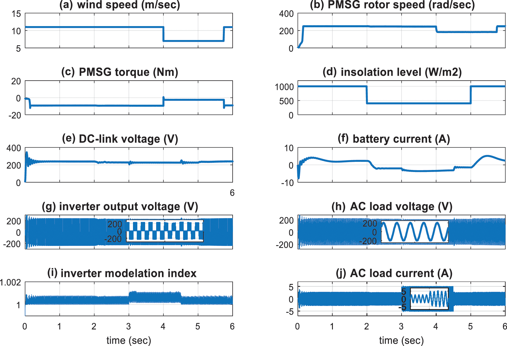
Figure 8: The simulation results with step-change in the wind speed, the irradiation level, and the load based on CSA (a) Wind speed (b) PMSG shaft speed (c) PMSG shaft torque (d) PV irradiation level (e) DC-Link voltage (f) Battery current (g) Inverter voltage(h) Load voltage (i) Inverter modulation index (j) Load current
Figure 9: The simulation results with step-change in the wind speed, the irradiation level, and the load based on CSA with parameters change. (a) Wind speed (b) PMSG shaft speed (c) PMSG shaft torque (d) PV irradiation level (e) DC-Link voltage (f) Battery current (g) Inverter voltage(h) Load voltage (i) Inverter modulation index (j) Load current
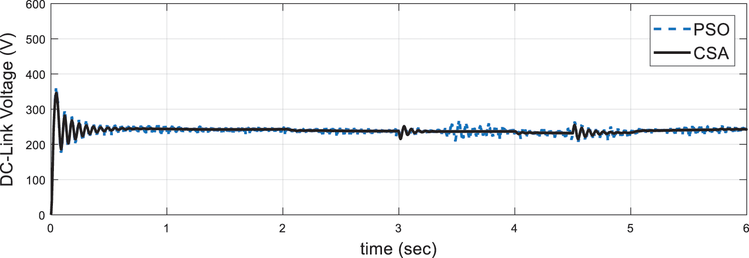
Figure 10: DC-Link voltage with step-change in the wind speed, the irradiation level, and the load based on PSO and CSA
This research introduces the modeling and energy management of an isolated wind/PV microgrid power system supported by an optimal controller design using the CSA algorithm. The system incorporates an energy storage system to enhance the power system’s efficiency and sustainability. The whole system components are modeled and simulated using the Matlab/Simulink platform. The proposed microgrid response is simulated under step variations in load demand, wind power, and the PV irradiation level. The results showed that the proposed renewable-energy-based microgrid system fed the load perfectly and tracked the required load demand under all disturbances. Moreover, the DC bus voltage is kept at its desired value and so is the AC load voltage and frequency for the applied disturbances. The performance of the storage system is excellent with the unstable wind speed and variable solar irradiation. The charging and discharging processes of the ESS are perfectly controlled to compensate for the variations in the wind and PV energies Also, the results with the optimal CSA controller are compared to that with the PSO algorithm at the same conditions. It is also found that the optimal CSA controller provides better responses regarding the overshoots and settling times. The main limitations of the proposed controller may be the trapping of CSA at local minima or having premature convergence.
Acknowledgement: The authors extend their appreciation to the Deanship of Scientific Research of the University of Tabuk for funding this work through Research Group Grant number S-1441-0055.
Funding Statement: This research was funded by the University of Tabuk, Grant Number S-1441-0055.
Conflicts of Interest: The authors declare that they have no conflicts of interest to report regarding the present study.
1. G. Francois and Z. M. Salameh, “Steady-state performance of a grid-connected rooftop hybrid wind-photovoltaic power system with battery storage,” IEEE Transactions on Energy Conversion, vol. 16, no. 1, pp. 1–7, 2001. [Google Scholar]
2. M. Mosadeghy, R. Yan and T. K. Saha, “A time-dependent approach to evaluate the capacity value of wind and solar PV generation,” IEEE Transactions on Sustainable Energy, vol. 7, no. 1, pp. 129–138, 2016. [Google Scholar]
3. M. Rezkallah, A. Hamadi, A. Chandra and B. Singh, “Design and implementation of active power control with improved P&O method for wind-PV-battery-based standalone generation system,” IEEE Transactions on Industrial Electronics, vol. 65, no. 7, pp. 5590–5600, 2018. [Google Scholar]
4. J. M. Guerrero, M. Chandorkar, T. Lee and P. C. Loh, “Advanced control architectures for intelligent microgrids—part i: Decentralized and hierarchical control,” IEEE Transactions on Industrial Electronics, vol. 60, no. 4, pp. 1254–1262, 2013. [Google Scholar]
5. S. Parhizi, H. Lotfi, A. Khodaei and S. Bahramirad, “State of the art in research on microgrids: A review,” IEEE Access, vol. 3, pp. 890–925, 2015. [Google Scholar]
6. A. Alhejji, A. Kuriqi, J. Jurasz and F. K. Abo-Elyousr, “Energy harvesting and water-saving in arid regions via solar PV accommodation in irrigation canals,” Energies, vol. 14, no. 9, pp. 2620, 2021. [Google Scholar]
7. J. Almorox, C. Voyant, N. Bailek, A. Kuriqi and J. A. Arnaldo, “Total solar irradiance’s effect on the performance of empirical models for estimating global solar radiation: An empirical-based review,” Energy, vol. 236, no. 3, pp. 121486, 2021. [Google Scholar]
8. A. Chaib, D. Achour and M. Kesraoui, “Control of a solar PV/wind hybrid energy system,” Energy Procedia, Elsevier, vol. 95, no. 10, pp. 89–97, 2016. [Google Scholar]
9. A. Merabet, K. T. Ahmed, H. Ibrahim, R. Beguenane and A. M. Y. M. Ghias, “Energy management and control system for laboratory-scale microgrid based wind-PV-battery,” IEEE Transactions on Sustainable Energy, vol. 8, no. 1, pp. 145–154, 2017. [Google Scholar]
10. S. Bae and A. Kwasinski, “Dynamic modeling and operation strategy for a microgrid with wind and photovoltaic resources,” IEEE Transactions on Smart Grid, vol. 3, no. 4, pp. 1867–1876, 2012. [Google Scholar]
11. S. Puchalapalli, S. K. Tiwari, B. Singh and P. K. Goel, “A microgrid based on wind-driven DFIG, DG, and solar PV array for optimal fuel consumption,” IEEE Transactions on Industry Applications, vol. 56, no. 5, pp. 4689–4699, 2020. [Google Scholar]
12. A. A. A. Radwan and Y. A. I. Mohamed, “Grid-connected wind-solar cogeneration using back-to-back voltage-source converters,” IEEE Transactions on Sustainable Energy, vol. 11, no. 1, pp. 315–325, 2020. [Google Scholar]
13. F. Chishti, S. Murshid and B. Singh, “Development of wind and solar-based AC microgrid with power quality improvement for local nonlinear load using MLMS,” IEEE Transactions on Industry Applications, vol. 55, no. 6, pp. 7134–7145, 2019. [Google Scholar]
14. X. Li, D. Hui and X. Lai, “Battery energy storage station (BESS)-based smoothing control of photovoltaic (PV) and wind power generation fluctuations,” IEEE Transactions on Sustainable Energy, vol. 4, no. 2, pp. 464–473, 2013. [Google Scholar]
15. S. A. Zaid, H. Albalawi, K. S. Alatawi, H. W. El-Rab, M. E. El-Shimy et al., “Novel fuzzy controller for a standalone electric vehicle charging station supplied by photovoltaic energy,” Applied System Innovation, vol. 4, no. 3, pp. 63, 2021. [Google Scholar]
16. Z. A. Arfeen, A. B. Khairuddin, R. M. Larik and M. S. Saeed, “Control of distributed generation systems for microgrid applications: A technological review,” International Transactions on Electrical Energy Systems, vol. 29, no. 9, pp. 1–26, 2019. [Google Scholar]
17. D. Chitara, K. R. Niazi, A. Swarnkar and N. Gupta, “Cuckoo search optimization algorithm for designing of a multimachine power system stabilizer,” IEEE Transactions on Industry Applications, vol. 54, no. 4, pp. 3056–3065, 2018. [Google Scholar]
18. M. Malik, I. Azim, A. H. Dar and S. Asghar, “An adaptive SAR despeckling method using cuckoo search algorithm,” Intelligent Automation & Soft Computing, vol. 29, no. 1, pp. 165–182, 2021. [Google Scholar]
19. X. Yang and S. Deb, “Cuckoo search via lévy flights,” in Proc. of 2009 World Congress on Nature & Biologically Inspired Computing (NaBIC), Coimbatore, India, pp. 210–214, 2009. [Google Scholar]
20. X. S. Yang and S. Deb, “Engineering optimisation by cuckoo search,” International Journal of Math Modeling & Numerical Optimization, vol. 1, no. 4, pp. 330–343, 2010. [Google Scholar]
21. D. N. Vo, P. Schegner and W. Ongsakul, “Cuckoo search algorithm for non-convex economic dispatch,” IET Generation Transmission & Distribution, vol. 7, no. 6, pp. 645–654, 2013. [Google Scholar]
22. A. A. El-Fergany and A. Y. Abdelaziz, “Capacitor allocations in radial distribution networks using cuckoo search algorithm,” IET Generation Transmission & Distribution, vol. 8, no. 2, pp. 645–654, 2014. [Google Scholar]
23. A. Y. Abdelaziz and E. S. Ali, “Cuckoo search algorithm-based load frequency controller design for nonlinear interconnected power system,” International Journal of Electrical Power & Energy Systems, vol. 73, no. 12, pp. 632–643, 2015. [Google Scholar]
24. I. E. Atawi, A. M. Kassem and S. A. Zaid, “Modeling management, and control of an autonomous wind/fuel cell micro-grid system,” Processes, vol. 7, no. 2, pp. 85, 2019. [Google Scholar]
25. M. Rashid, Power Electronics Handbook. The Netherlands: Elsevier Academic Press, 2011. [Google Scholar]
26. K. Vijayalakshmi and P. Anandan, “Global levy flight of cuckoo search with particle swarm optimization for effective cluster head selection in wireless sensor network,” Intelligent Automation & Soft Computing, vol. 26, no. 2, pp. 303–311, 2020. [Google Scholar]
27. H. Zhang, B. Zhu, K. Pang, C. Chen and Y. Wan, “Identification of abnormal patterns in AR (1) process using CS-SVM,” Intelligent Automation & Soft Computing, vol. 28, no. 3, pp. 797–810, 2021. [Google Scholar]
 | This work is licensed under a Creative Commons Attribution 4.0 International License, which permits unrestricted use, distribution, and reproduction in any medium, provided the original work is properly cited. |