DOI:10.32604/iasc.2022.026055
| Intelligent Automation & Soft Computing DOI:10.32604/iasc.2022.026055 | |
| Article |
Intelligent Measurement and Monitoring by Integrating Fieldbus and Robotic Arm
1Department of Electrical Engineering, National Chin-Yi University of Technology, Taichung, 411030, Taiwan
2Department of Information Technology, Takming University of Science and Technology, Taipei City, 11451, Taiwan
*Corresponding Author: Sung-Jung Hsiao. Email: sungjung@gs.takming.edu.tw
Received: 14 December 2021; Accepted: 10 February 2022
Abstract: In response to the rapid global development of industrial technologies and the resulting rapid growth in the production lines of industry and manufacturing, traditional manufacturing must become intelligent and automated, and undergo the process of informatization. Machines can reduce human errors, replace manpower, and even work better than manpower in certain aspects. Over recent years, the Internet of Things (IoT) has been applied in a wide range of fields. IoT helps control all the production information of factories in real time, and accordingly, reduces labor cost, improves quality, efficiently handles exceptions, and swiftly meets market demands, and how to achieve such a goal is a focus of current studies. This study proposes an IoT-based communication system that can monitor the operations of robotic arms and return data to users through a system interface in real time. This communication system is based on Fieldbus as the system architecture, and utilizes HIWIN Company (HI-tech WINner) Robot System Software (HRSS) and an electric gripper’s intelligent measurement function to collect and analyze data. On this basis, this study efficiently determines whether the quality of products meets the standard, and uses the Weintek human-machine interface to remotely adjust robotic arms to achieve intelligent monitoring.
Keywords: Internet of things; fieldbus; HIWIN robot system software (HRSS); weintek man-machine interface; modbus
Industry 4.0 was first proposed by Germany, and to date, Industry 4.0 has not completely replaced Industry 3.0, as it is still in the transition period from Industry 3.0 to Industry 4.0. The German government expects to maximize production automation in the next 10 to 15 years with the IoT and big data as core technologies of Industry 4.0, and replace more and even all manpower with robots, in order to ultimately achieve “unmanned factories”. IoT is generally defined as collecting data for big data analysis by combining systems and machines, and the corresponding results are used to make business transformations or decisions, and to achieve intelligent industrial operation. Nowadays, industry and manufacturing are transitioning to automated production. Industry 4.0, which is a German strategic initiative, is aimed at creating intelligent factories by interconnecting all factory components over a network to combine automation and intelligence. The vision for intelligent factories is shown in Fig. 1a [1,2].
This paper proposed a Fieldbus-based robotic arm remote control system that uses HIWIN Robot System Software (HRSS), the Weintek human-machine interface (model: MT8102ie), and the Modbus communication protocol. Through the Weintek human-machine interface, operators can remotely monitor robotic arms and collect data (such as, the axial direction of a robotic arm, Input/Output signals, program modification, and detection of end devices) for data analysis and problem handling, in order to achieve intelligent manufacturing.

Figure 1: (a) The architecture for intelligent factories (b) Modbus/TCP data transfer format
2.1 Fieldbus Communication Protocol
Fieldbus is a general term for various industrial communication protocols. Before the emergence of Fieldbus, most industrial controller systems were interconnected through the RS232 protocol for serial communications. As it was limited by the techniques and communication formats, Fieldbus could only support communications between two devices [3,4]. Now, Fieldbus is integrated with Ethernet to a greater extent, which allows connecting multiple field devices to any endpoint or controller, thus, Fieldbus is a set of protocols other than a connection type. The fieldbus technology appeared in 1988 with the completion of the ISA S50.02 standard; however, the development of the international standard took a long period of time. In 1999, the SC65C/WG6 Committee on the Standards of the International Electrotechnical Commission (IEC) held a meeting where the IEC 61158 standard was passed. The standard defined eight types of protocols. In 2008, IEC updated the IEC 61158 standard, which increased the original eight protocols to 15 protocols (Communication Profile Families, CPF) [5].
As discussed above and proposed by Modicone (Schneider Electric) in 1978, Modbus is a communication protocol contained in Fieldbus. Modbus, which uses Programmable logic controller (PLCs) for communications, is applied in a wide range of industrial control fields due to its ease of use and low resource consumption. Modbus allows serial interconnections with various devices, such as PLCs, industrial computers, and industrial robots. In 1998, Schneider proposed Modbus Transmission Control Protocol (TCP) over TCP/ Internet Protocol (IP) Ethernet, which made the application layer of Modbus applicable to more sectors for data collection over the Ethernet [6]. The Modbus communication protocol uses master-slave architecture. One device is the master and other devices are slaves. Each slave contains a unique address, which is used to connect to and communicate with the slave [7]. The Modbus protocol has many versions that are used for serial ports (RS-232, RS-422, and EIA-485) and Ethernet, which support Internet Protocol. Most Modbus devices communicate with one another through serial port EIA-485. The frame defined in the Modbus communication protocol [8] contains four fields: device address, function code, data, and error check code.
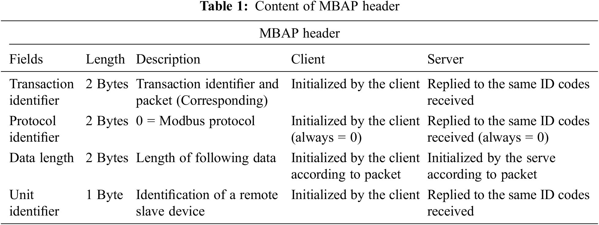
Modbus provides three data transfer modes: Modbus/ASCII (American Standard Code for Information Interchange), Modbus RTU (Remote Terminal Unit), and Modbus Ethernet TCP. These modes use different data formats. Modbus ASCII uses the easy hexadecimal ASCII (hex-ASCII) to encode data. A colon (:) is added to the start in the frame followed by the address, function code, data, and Longitudinal Redundancy Check (LRC). Carriage return and line feed are added to the end. A distinguishing characteristic of Modbus/RTU is no specific start or end character, and the use of binary coding and strong CRC error-checking. A Modbus/RTU message contains a device address, function code, data, and CRC [9]. The data transfer format, as defined in the Modbus/TCP protocol, must be complied with to allow data transfer between devices through the network and application layers using the Modbus protocol in the Modbus/TCP mode, as shown in Fig. 1b [10,11]. In addition to the basic format content in a message, the function code, and data, a Modbus Application Protocol header must be added to the start of a message. The header contains four fields: transaction identifier, protocol identifier, length, and unit identifier, as listed in Tab. 1.
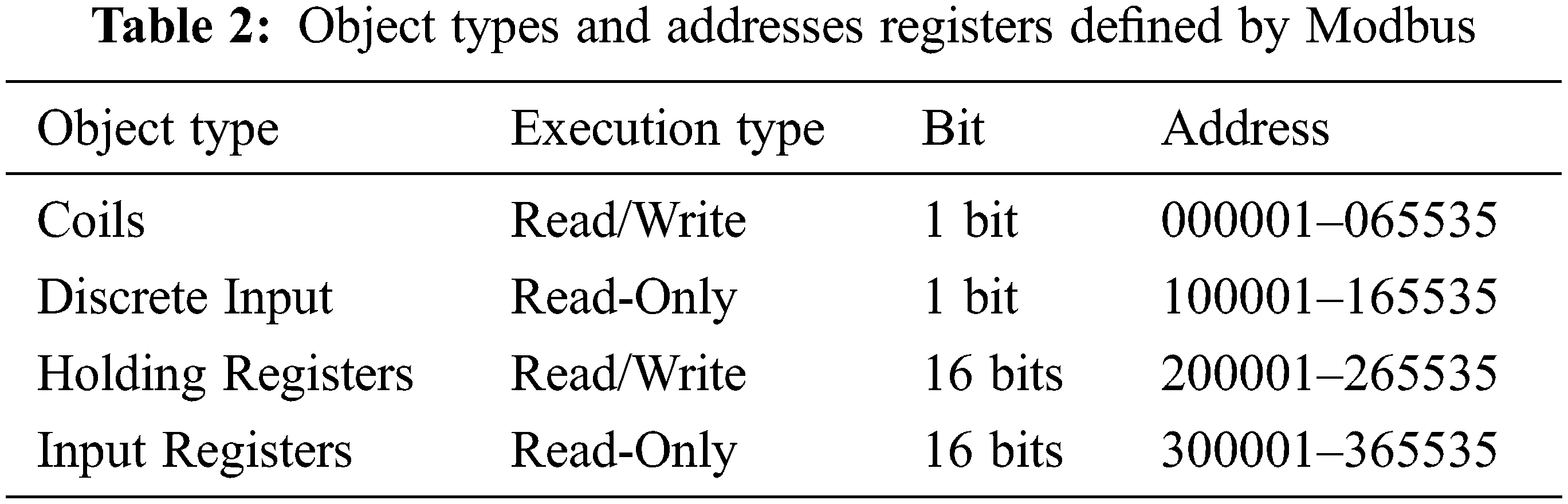
The Modbus/TCP protocol defines that the protocol identifier must be 0, and the data length is the byte count of the following fields starting from the Unit Identifier. The Modbus protocol defines the following object types: coils, discrete input, holding registers, and input registers, as listed in Tab. 2. Lists the addresses of the object registers defined by Modbus, where each object type has 65,535 reference addresses, and different registers can be planned according to specific products. Furthermore, Modbus also defines function codes for various purposes according to different object types [12].
Accuracy refers to how close an average value of successive measurements (measured value) of the same variable under the same measurement conditions (same operator, same measurement system: 2D, 3D, or vernier caliper) is to the actual (true) value; for example, the error between an average measured value and the actual (true) value. Precision refers to how close the measured values of the same variable under the same measurement conditions (same measurement method) are to each other [13–15].

Figure 2: Relationship between accuracy and precision (a) Both accurate and precise (b) inaccurate and inaccurate (c) Accurate but not precise (d) Precise and inaccurate (e) System architecture
Fig. 2 shows the relationship between accuracy and precision, and measured values must be both accurate and precise [16,17]. The result shown in Fig. 2a should be obtained if both the measurement instrument and the operator are stable and reliable. Fig. 2b indicates that both the measurement instrument and the operator are unreliable. In this case, the operator should immediately stop operation, and review and identify the problem; otherwise, inaccurate values will result in critical quality incidents and wrong decisions [18]. Fig. 2c indicates that there is a high probability that the operator used a defective measurement method or technique, and corrective measures should be taken. Fig. 2d indicates that the measurement instrument was defective, meaning inaccurate measured values were obtained despite a skilled operator. In this case, the operator needs to calibrate the instrument.
The term regression was introduced by Sir F. Galton, a British eugenicist, in the paper Regression towards mediocrity in hereditary stature in 1885, which conducted a study on the correlation between the heights of children and their parents. He showed that the height of children from very short or very tall parents would move towards the average, and called this phenomenon “regression to the mean” [19].
Regression analysis is aimed at determining the correlation between two or more variables, and building a mathematical model to observe certain variables to identify quality or incident factors, in order to facilitate judgment and study. Regression Analysis can be divided into simple regression and multiple regression. Simple regression explores the correlation between one dependent variable and one independent variable. Multiple regressions explore the correlation between one dependent variable and multiple independent variables. The following describes the formulas for simple regression and multiple regressions [20]:
Formula for Simple Regression:
where, Y: Predicted result; β0: A constant; β1: Regression coefficient; X1: Influence factor; ε: Error (residual error)
Formula for Multiple Regression:
where, Y: Predicted result; β0: A constant; β1…….. βn: Regression coefficient; X1: Influence factor; ε: Error (residual error)
This study used the regression analysis suite in Excel to analyze the variance between manually and automated measured values to build a regression analysis model.
3 System Architecture and Hardware Devices
This study divided the system architecture into three parts, as based on IoT: sensing layer, network layer, and application layer, as shown in Fig. 2e. At the sensing layer, an end device (electric gripper) was installed on a robotic arm to hold a workpiece for monitoring the dimensions of the processed workpiece, the processing errors, and determining whether the workpiece is defective. At the network layer, data was collected using the electric gripper and the robotic arm, and was sent to a computer through the HRSS installed in the master control computer and the SWITCH network switch for data analysis and statistics.
3.1.1 Work Process of the Monitoring System
The Fig. 3a presents the work process of the monitoring system, which involves gripping, and placing the processed parts with the end device (electric gripper) on the robotic arm, and sending the measured values to HRSS, which in turn transfers the data to a computer or cloud software for storage or preparing a table or chart. The operator can use such data to improve processing conditions or machine utilization.

Figure 3: (a) The architecture of the monitoring system (b) Work process of the remote-control system
3.1.2 Work Process of the Remote-Control System
Fig. 3b shows the work process of the remote-control system, which provides the results of data analysis, as implemented in the computer by the operator, in order to determine whether or not to change program parameters. Through the Weintek human-machine interface, the operator can modify the HRSS arm parameters and end clamping force, and save the modified values, and the processing data is continuously returned for records.
This system used an ASUS P5440U laptop computer as the Modbus message window. The developed HRSS application was installed in this computer, and used to connect to the end electric gripper and the human interface device. This system used the Weintek human-machine interface (model: MT8102ie). The operator could control the robotic arm and modify parameters on this interface through a network port and computer link. The Fig. 4a shows the Weintek human-machine interface.

Figure 4: (a) Weintek human-machine interface (b) The HIWIN electric gripper XEG-32 (c) Operating inference of HRSS
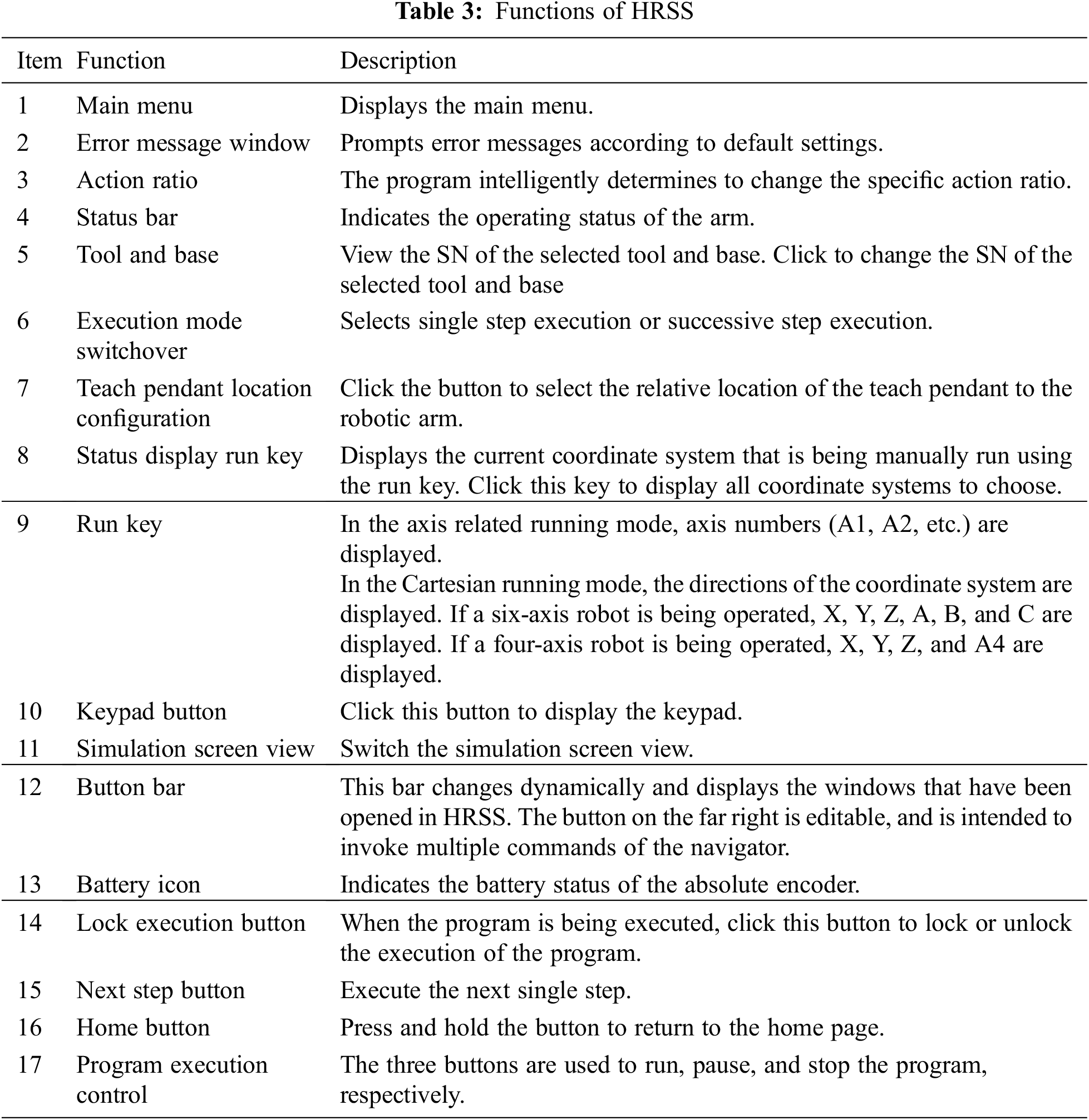
HIWIN Robot System Software (HRSS) is combined the HIWIN and HRSS, the HIWIN electric gripper XEG-32 is equipped with a stepper motor combined with an encode HRSS r and is a two-finger type intelligent gripper with intelligent functions, such as auto-tuning original reset, gripping force model establishment, instant self-adjusting clamping force, stroke boundary detection and correction. It can also output the signals of the gripper state, abnormal alarms, object identification, etc. Fig. 4b shows the HIWIN electric gripper XEG-32 lists its specifications. HRSS is a free human-machine interface developed by HIWIN. Users can download HRSS from the official website of HIWIN and install it in their computers for use. The HRSS includes all functions for HIWIN’s robots, such as I/O signal, counter, and communication test. Even without a robotic arm, users can use HRSS for offline simulation. The programming language used by HRSS is similar to C and C++, meaning it offers ease of use. Fig. 4c shows the operating interface of HRSS, and Tab. 3 describes the functions of HRSS marked in Fig. 4c.
The XEG-W1+ electric gripper software is developed by HIWIN. With this software, operators can easily control the electric gripper, and set up complex instructions, such as gripping range, object recognition, value interpretation, and actions (move, grip, read, write, etc.). With a robotic arm, PLC, and a linear motor module, when the end device grips and senses an object, the software can return data to the operator for intelligent monitoring. The software provides a simple interface for ease of use. Fig. 5a [21] shows the operating interface of the EG-W1+ electric gripper software, and Tab. 4 describes the functions of HRSS marked in Fig. 5a.

Figure 5: (a) Operating interface of the XEG-W1+ electric gripper software (b) Manual measurement operations

3.3 Experimental Simulations and Result Analysis
To understand the differences in accuracy and stability between an automated measurement system and manual measurement, this study implemented ANOVA, prepared control charts for variables, and implemented regression analysis to analyze whether traditional factories can reduce manpower in quality testing and defect screening by introducing Industry 4.0 and innovating with robotic arms and electric grippers for intelligent measurement. Furthermore, the parameters of robotic arms and electric grippers can be remotely returned, and object data can be returned to users for efficient management.
3.4 ANOVA Experimental Simulation
Data must be collected to understand the measurement accuracy of manual measurement and intelligent measurement using an electric gripper. Tab. 5 lists the manual measurement instrument and its specifications. In this experiment, the measurement objects were metric hexagon socket head cap screws (1/2) Dimensions: M6, M8, and M10, where the measured part was the screw head. Tab. 6 lists the measurement objects and their specifications. Dimension error tolerance was determined based on Page 5 of the standard mechanical design handbook, as prepared by Fujio Oguri and Atsuo Oguri [22].


First, three engineers (operator A, operator B, and operator C) manually measured metric hexagon socket head cap screws M6, M8, and M10 for five times, respectively, using the same Mitutoyo electronic caliper. The caliper was reset after each measurement to ensure the accuracy of the measurement instrument. The manual measurement operation pictures are shown in Fig. 5b.
Formulas for calculating the total variance of engineers A, B, and C are, as follows, respectively:
Then, this study used an electric gripper to collect data and implement experimental analysis. Tab. 7 listed the automated measurement instrument and its specifications.

The use of the HIWIN XEG-32 electric gripper required HRSS for automated measurement; therefore, HRSS was used for programming to collect data, as shown in Fig. 6a.

Figure 6: (a) Automated measurement program (b) Placement of a measurement object (c) Measured values were stored in the buffer
The three engineers (operator A, operator B, and operator C) performed automated measurements of metric hexagon socket head cap screws M6, M8, and M10 for five times, respectively, using the same electric gripper. In order to ensure the accuracy of the electric gripper, the electric gripper was reset after each measurement. The measurement object was placed in the measuring area of the electric gripper, as shown in the red box in Fig. 6b. [23,24] The automated measurement steps are, as follows: 1. Trigger DI3 in the program for an automated measurement. 2. Trigger DI2 to open the gripper after the measurement. 3. Remove the measurement object and reset the gripper. 4. Place the measurement object in the measuring position again and repeat steps 1 to 3 for another four times. Then, repeat steps 1 to 4 with another measurement object till completion of the measurement of all measurement objects. Measured values in each measurement were directly stored in the HRSS buffer, as shown in the red box in Fig. 6c. As the underlying computing method in HRSS required adding $C[A] = EG_GET_POS * 1000 in the program, each measured value was rounded to the third decimal place.
3.5 Control Charts for Variables
Data must be collected to understand the quality analysis variances, as resulted from manually measured values and intelligently measured values using an electric gripper. Tab. 8 lists the manual measurement instrument and its specification.

This study also used the electric gripper to collect data for preparing the Xbar-R control charts and implementing experimental analysis. Fig. 7 lists the automated measurement instrument and its specifications. The use of the electric gripper required HRSS for automated measurement; therefore, HRSS was used for programming to collect data, as shown in Fig. 8.

Figure 7: (a)

Figure 8: (a)
This experiment used three independent variables: measurement time, screw dimensions, and number of measurements. These three variables are considered as major factors for measurement errors.
3.6.1 Regression Analysis of Manual Measurement and Automated Measurement
This experiment engaged 15 operators with different years of service to obtain random measurement times, M6 screw dimensions, and the number of measurements, in order to compare manual measurement results with automated measurement results. First, this study collected data on years of service, random measurement time, M6 screw dimensions, and number of measurements. The R2 and P-values of measurement time (min), M6 screw dimensions (mm), and the number of measurements in manual measurement were obtained and compared, and then, analyzed under the level of significance α = 0.05 to determine whether manual measurement was correlated with measurement time (min), M6 screw dimensions (mm), and the number of measurements [25,26].
b1, b2, and b0 were obtained using the data listed in the preceding table through a multiple regression equation.
The statistics of the multiple regression equation are estimated, as follows:
R2 and modified R2 were calculated using the preceding statistics of the multiple regression equation.
The formulas for calculating the modified R2 are, as follows:
Fig. 9a Regression analysis for manual measurement. The coefficient of correlation R2 is 0.59, and the modified R2 is 0.49, which have minor differences with the calculated results using the preceding formulas. A R2 value that is more approximate to 1 means a smaller prediction error. Fig. 9b Regression analysis for automated measurement. The coefficient of correlation R2 is 0.26, and the modified R2 is 0.062, which have minor differences with the calculated results using the preceding formulas. A R2 value more approximate to 1 means a smaller prediction error.

Figure 9: (a) Regression analysis for manual measurement in Excel (b) Regression analysis for automated measurement in Excel
3.7 System Implementation and Application
3.7.1 System Monitoring Interface
This study used the Fieldbus interconnection technique to connect a laptop computer to a HIWIN robotic arm and electric gripper, as shown in Fig. 10a. The experiment opened HRSS, set the electric gripper, and selected the model and specifications to connect. The measured values, as obtained by using the electric gripper to hold the measurement object, were stored in the HRSS buffer, as shown in Fig. 10b. The measured values were then exported to the laptop computer through Modbus, as shown in Fig. 10c, in order to prepare the Excel file, as shown in Fig. 11a, then, the file was edited for analysis and study. When the electric gripper failed to grip a measurement object or the dimensions of the measurement object were abnormal, an error message was displayed, as shown in Figs. 11b and 11c, in order to prompt the operator to handle the issue and prevent the production of a large amount of defective products.

Figure 10: (a) Connection between the electric gripper and the robotic arm (b) The measured values were stored in the buffer (c) Data was transferred to the computer through Modbus

Figure 11: (a) An Excel file was exported from HRSS (b) An error message was displayed indicating that the electric gripper failed to hold the measurement object (c) An error message was displayed indicating that the dimensions of the measured object were abnormal
3.7.2 Remote Monitoring Interface
As mentioned in the preceding section, the robotic arm utilized the Fieldbus interconnection technology for data collection and monitoring. When a machine was abnormal or must be handled or adjusted, we could make adjustment through the system interface developed by ourselves. Fig. 12a shows the architecture of the remote system.

Figure 12: (a) The architecture of the remote system (b) The system interface was in the disconnected status (c) Steps to connect the system interface
The simulated remote-control system is comprised of a laptop computer, an electric gripper and the Weintek human-machine interface. First, this study opened the system interface, which was in the disconnected status, meaning no signal lamp was displayed in the upper right corner, as shown in the red box in Fig. 12b. The operators starts the HRSS and then sequentially presses the arm button, file button, fieldbus button, and setting button, and then connects the system, as shown in Fig. 12c. After the system interface was successfully connected, the Protcol2 indicator was lit in red, as shown in the red box in Fig. 13a; and the signal lamp in the upper right corner was displayed, as shown in Fig. 13b. Then, we proceeded with robotic arm adjustment.
The X, Y, Z, and C coordinates were the actual monitored positions of the robotic arm using HRSS, in order that we could better know the position of the robotic arm, as shown in the red box in Fig. 13c. To adjust the execution speed of the robotic arm, click Position in the system interface, and then, select X, Y, Z, and C to adjust. After the adjustment, click “OK” to save the changes. Then, the robotic arm would move based on the new position coordinates.

Figure 13: (a) The system interface was successfully connected (b) The system interface was successfully connected to HRSS (c) Coordinate values in HRSS and the remote control system
The Fieldbus interconnection technology was the basis for data collection and robotic arm status monitoring in this paper. The automated measurement function of the end electronic gripper was utilized to collect the dimension data of the measurement object, and the same data was exported for analysis and quality determination. In this manner, operators can analyze the probability of defects in current production, understand whether there are problems in a production line as early as possible, and monitor the conditions of the production line in real time. Furthermore, HRSS was connected to the remote control system to allow operators to handle and tune gripper position remotely, rather than conducting on-site handling and adjustment with a teaching pendant.
This paper aimed at realizing an extension of intelligent manufacturing, as proposed by Industry 4.0, to address the unnecessary losses caused by human errors in traditional manufacturing, which relies on manpower-intensive production, manufacturing, quality control, and monitoring. This paper proposed a remote-control system that features automated measurement, data collection, and status monitoring, as based on the Fieldbus communication protocol, by integrating several intelligent products to achieve the purpose of the IoT and intelligent manufacturing. This system is comprised of HRSS, an electric gripper, and a human-machine interface, and uses the Modbus TCP/IP Ethernet in the Fieldbus communication protocol to collect test data. In order to analyze whether the data collected using this system is reliable to allow operators to quickly analyze data and reduce human errors, this study compared the automated measurements using this system and manual measurements. According to the results of variance analysis in the preceding experimental sections, the accuracy of manual measurements depend on the operator’s skills and mental state, and is uncorrelated to the type of measurement object.
This study used one robotic arm, one electronic gripper, one computer, and one control interface to control and collect data. If this system is applied in factories in the future, one computer can receive and collect the data transferred from multiple robotic arms, and centrally control these robotic arms, in order to save labor and time. In this manner, operators can handle problems as early as possible and prevent the production of defective products. In subsequent studies, other end and sensing devices, as well as visual devices, can be introduced to collect diversified data, meaning more than just the dimensions of measurement objects, in order to help factories transition to intelligent factories and improve their competitiveness.
Acknowledgement: This research was supported by the Department of Electrical Engineering, National Chin-Yi University of Technology. The authors would like to thank the National Chin-Yi University of Technology, Takming University of Science and Technology, Taiwan, for financially supporting this research
Funding Statement: The authors received no specific funding for this study.
Conflicts of Interest: The authors declare that they have no conflicts of interest to report regarding the present study.
1. B. Bajic, A. Rikalovic, N. Suzic and V. Piuri, “Industry 4.0 implementation challenges and opportunities: A managerial perspective,” IEEE Systems Journal, vol. 15, no. 1, pp. 546–559, 2021. [Google Scholar]
2. Y. Liu, X. Ma, L. Shu, G. P. Hancke and A. M. Abu-Mahfouz, “From industry 4.0 to agriculture 4.0: Current status, enabling technologies, and research challenges,” IEEE Transactions on Industrial Informatics, vol. 17, no. 6, pp. 4322–4334, 2021. [Google Scholar]
3. Z. You and L. Feng, “Integration of industry 4.0 related technologies in construction industry: A framework of cyber-physical system,” IEEE Access, vol. 8, pp. 122908–122922, 2020. [Google Scholar]
4. S. A. Dadenkov, A. N. Kamenskikh and E. L. Kon, “Algorithm for design fieldbus infrastructure of DCS design of fieldbus-network,” in Proc. 2017 XX IEEE Int. Conf. on Soft Computing and Measurements (SCM), St. etersburg, Russia, pp. 213–216, 2017. [Google Scholar]
5. C. Xi, L. Zhang, Y. Zhang and W. Sun, “The reliable and traceable design of fieldbus network applied in nuclear power plant,” in Proc. 2019 IEEE 4th Advanced Information Technology, Electronic and Automation Control Conf. (IAEAC), Chengdu, China, pp. 2526–2529, 2019. [Google Scholar]
6. T. P. Mussolini, F. G. R. Ramos, R. L. Moreno and T. C. Pimenta, “Development of foundation fieldbus h1 controller IC,” in Proc. 2019 IEEE 10th Latin American Symp. on Circuits & Systems (LASCAS), Armenia, Colombia, pp. 213–216, 2019. [Google Scholar]
7. B. Li and Y. Pei, “Measures for error avalanche and energy avalanche effect in secure wireless fieldbus systems,” China Communications, vol. 16, no. 2, pp. 202–214, 2019. [Google Scholar]
8. A. Maalla, “Research on fault diagnosis of fieldbus state in converter station,” in Proc. 2019 IEEE 3rd Information Technology, Networking, Electronic and Automation Control Conf. (ITNEC), Chengdu, China, pp. 2553–2557, 2019. [Google Scholar]
9. S. Mangkalajan, W. Koodtalang, T. Sangsuwan and N. Pudchuen, “Virtual process using LabVIEW in combination with modbus TCP for fieldbus control system,” in Proc. 2019 9th IEEE Int. Conf. on Control System, Computing and Engineering (ICCSCE), Penang, Malaysia, pp. 21–24, 2019. [Google Scholar]
10. P. Pannil, S. Jaroenla, A. Julsereewong and S. Kummool, “Feedforward hybrid control using foundation fieldbus: A case study of temperature control with DeltaV system,” in Proc. 2018 3rd Int. Conf. on Control and Robotics Engineering (ICCRE), Nagoya, Japan, pp. 104–108, 2018. [Google Scholar]
11. H. Gang, Y. Zhilou, C. Naikuo, F. Guirong, Z. Lei et al., “Development of OPC UA based centralized server fieldbus data high efficiency transmit architecture,” in Proc. 2020 39th Chinese Control Conf. (CCC), Shenyang, China, pp. 4580–4585, 2020. [Google Scholar]
12. S. Zang and L. Xu, “Design about the pressure hole device cleaning mechanism of the precision seeder based on TRIZ theory,” in Proc. 2018 Int. Conf. on Robots & Intelligent System (ICRIS), Changsha, China, pp. 66–69, 2018. [Google Scholar]
13. F. Deeba and R. Rohling, “Repeatability and reproducibility of quantitative ultrasound parameter estimation using spatially weighted total variation (SWTV) regularization,” in Proc. 2020 IEEE Int. Ultrasonics Symp. (IUS), Las Vegas, NV, USA, pp. 1–4, 2020. [Google Scholar]
14. Y. M. Ling, Y. J. Chen and C. F. Chien, “A measurement system analysis research framework for measurement system and empirical study with automation time-domain measurements,” in Proc. 2019 Joint Int. Symp. on e-Manufacturing & Design Collaboration (eMDC) & Semiconductor Manufacturing (ISSM), Hsinchu, Taiwan, pp. 1–4, 2019. [Google Scholar]
15. X. Li, “The relationship between cognition function and three factors based on big data and ANOVA text,” in Proc. 2020 Int. Conf. on Big Data and Social Sciences (ICBDSS), Xi’an, China, pp. 24–28, 2020. [Google Scholar]
16. H. Wibowo, D. Nurpratama, W. Suharso, A. E. Minarno and G. Wasis, “Impact evaluation of procedurally content generated against immersion games using ANOVA,” in Proc. 2020 8th Int. Conf. on Information and Communication Technology (ICoICT), Yogyakarta, Indonesia, pp. 1–6, 2020. [Google Scholar]
17. W. K. Lau, Z. L. Chong and P. S. Ng, “One-sided variable sampling interval control chart for monitoring the coefficient of variation,” in Proc. 2018 4th Int. Conf. on Electrical, Electronics and System Engineering (ICEESE), Kuala Lumpur, Malaysia, pp. 40–43, 2018. [Google Scholar]
18. M. B. C. Khoo, J. L. Khoo, W. C. Yeong and W. L. Teoh, “A comparative study between the variable sampling interval X and double sampling X charts,” in Proc. 2016 IEEE Int. Conf. on Control and Robotics Engineering (ICCRE), Singapore, pp. 1–4, 2016. [Google Scholar]
19. S. Liu, L. Fang, Z. Zhou and Y. Hong, “Uncertain Box-Cox regression analysis with rescaled least squares estimation,” IEEE Access, vol. 8, pp. 84769–84776, 2020. [Google Scholar]
20. Liu Y., Zhang R., Nie F., Li X. and Ding C., “Supervised dimensionality reduction methods via recursive regression,” IEEE Transactions on Neural Networks and Learning Systems, vol. 31, no. 9, pp. 3269–3279, 2019. [Google Scholar]
21. J. Y. Kuo and K. T. Song, “A design for remote center of motion control using a software computing approach,” in Proc. 2020 Int. Automatic Control Conf. (CACS), Hsinchu, Taiwan, pp. 1–5, 2020. [Google Scholar]
22. T. P. Phan, P. C. P. Chao, J. J. Cai, Y. J. Wang and S. C. Wang, “A novel 6-DOF force/torque sensor for COBOTs and its calibration method,” in Proc. 2018 IEEE Int. Conf. on Applied System Invention (ICASI), Chiba, Japan, pp. 1228–1231, 2018. [Google Scholar]
23. T. H. S. Li, P. H. Kuo, Y. F. Ho and G. H. Liou, “Intelligent control strategy for robotic arm by using adaptive inertia weight and acceleration coefficients particle swarm optimization,” IEEE Access, vol. 7, pp. 126929–126940, 2019. [Google Scholar]
24. J. Desai, B. Schabron and Y. Yihun, “Force Myography controlled intelligent assistive wheelchair-mounted robotic exoskeleton for arm movements,” in Proc. 2019 IEEE Int. Symp. on Measurement and Control in Robotics (ISMCR), Houston, TX, USA, 2019. [Google Scholar]
25. M. Farag, A. N. A. Ghafar and M. H. Alsibai, “Real-time robotic grasping and localization using deep learning-based object detection technique,” in Proc. 2019 IEEE Int. Conf. on Automatic Control and Intelligent Systems (I2CACIS), Selangor, Malaysia, 2019. [Google Scholar]
26. R. Shiva, G. Vimal, M. Kaviyarasu and K. J. Lakshmi, “Intelligent farming using delta robot,” in Proc. 2020 Int. Conf. on Power, Energy, Control and Transmission Systems (ICPECTS), Chennai, India, 2020. [Google Scholar]
 | This work is licensed under a Creative Commons Attribution 4.0 International License, which permits unrestricted use, distribution, and reproduction in any medium, provided the original work is properly cited. |