DOI:10.32604/iasc.2022.026651
| Intelligent Automation & Soft Computing DOI:10.32604/iasc.2022.026651 | |
| Article |
Adaptive Multicale Transformation Run-Length Code-Based Test Data Compression in Benchmark Circuits
Department of Electronics and Communication Engineering, K.S.R. College of Engineering, Tiruchengode, 637215, Tamilnadu, India
*Corresponding Author: P. Thilagavathi. Email: thilagaramaniece@gmail.com
Received: 31 December 2021; Accepted: 10 February 2022
Abstract: Test data volume reduction and power consumption during testing time outlines are two main problems for Very Large Scale Integration (VLSI) gadgets. Most the code-based arrangements have been utilized to diminish test data volume, although the most notable way that test data volume is high. The switching action that happens between the test carriers leads would expand power consumption. This work presents a compression/decompression methodology for limiting the amount of test data that should be kept on a tester and conveyed to each center in a System on a Chip (SOC) during a test utilizing the Adaptive Multiscale Transformation Run Length Code (AMT-RLC). The data transmission capacity between the tester and the SOC is a block when testing modern SOCs with a few centers to check how long the test can run. The proposed work keeps the tester in the SOC and the test vectors in a compacted memory structure. A modest quantity of On-chip equipment is needed to release different test vectors. Due to its variouscharacteristics that decrease the test data volume, the Adaptive Multiscale Transformation Run Length Code is picked for a center test vector framework. These attributes ensure that the code words overhead is decoded (and applied to the center's output exhibit grouping commitment) utilizing an exact cell cluster that occupies less space. The suggested strategy may provide test data compression with much-reduced Area overhead for the decoder and low power consumption, according to the results. The abstract shall be running continuously (not structured) and shall not include reference citations. Abbreviations should be defined in full the first time they appear. Abbreviations could be then used, quoted in-between parentheses.
Keywords: Compression; decompression; run-length code; fault coverage
The most recent advancements in System-on-a-Chips (SoC) have combined the large growth in circuit density with late innovations in circuit density, test data volume, and test power dispersion. As the agility of SoCs grows, testing expenses such as difficulty and chip size are quickly increasing [1]. The SoC test is concerned with the vast amount of test data recorded in the test memory and transported to the test circuit. Test power is expected to consider the great responsibility for developing the exchange during the test, a massive activity in most testing power. Test Data Compression [2] offers SoCs test data volume and a favorable response about test time, high power and unique power abuse. The pre-registered test cluster for the Intellectual Property (IP) position is compressed with a little test, stored in the Advanced Test Equipment (ATE) memory. In the literature, many strategies for regulating test data, test application time, and power consumption volume in the test model were described [3,4]. Test data compression mode and Built-In Self-Test (BIST) techniques are effective ways [5,6]. Regardless of these methods, test data amount and test application time may be more suitable for compression system testing [7]. Regardless, this stabilized test set achieves reduced disclosure of non-physical errors shown. However, BIST does not require more draw test application time and is still the most commonly used logic test for memory testing. Alternative techniques used to reduce the amount of test data for system-on-chip depend on the data compression strategy used, for example, verification coding, run-length coding, and Columbus decoding [8,9]. None of these codes are logic circuits that reproduce the specific attributes of the pre-registered test set. The use of variable-length input Huffman to encode the press test data is presented in [10]. Be that as it may, the decoding intricacy for large square sizes of data compression for code-based methods makes it unacceptable for on-chip decompression. Like this, a substitute method has to defeat the downsides of test data compression. So in this work, use an Adaptive Multiscale Transformation Run-Length Code algorithm for test data compression and fault detection for benchmark circuits. The following methodologies are motivated for this research work.
i) To increase the compression ratio using efficient run-length coding compression methods.
ii) To introduce a compression/decompression scheme based on the Adaptive Multi-Scale Transformation Run Length Code (AMT-RLC) for reducing the amount of test data that needs to be saved on a tester and transferred to each core in a System on a Chip (SOC) during a test
iii) To compare these new techniques with conventional techniques to achieve less power dissipation, less memory and High fault coverage.
The rest of this work is organized into five sections: The introduction of test data compression is discussed in Section 1. The literature survey in Section 2 is based on current test data compression methods. The suggested Adaptive Multiscale Transformation Run Length Code is discussed in Section 3. (AMT-RLC). The suggested Adaptive Multiscale Transformation Run Length Code (AMT-RLC) based test data compression is discussed in Section 4 along with its simulation results and performance analysis. The conclusion of the Adaptive Multiscale Transformation Run Length Code (AMT-RLC) based test data compression is discussed in Section 5. It will speed up the review and typesetting process.
Three test compression strategies, including an appropriate direct decompression-based system [11], a broadcast check-based system, and a code-based system [12], can minimize the size of test data. Among them, it is a typical compression method, which uses the information required by the circuit from the immediate decompression-based system to the age of the fault generation or test configuration. The transmission check-based system then applies necessary data to the circuit displaying shortcomings through which the test grid is compressed and the test configuration is in progress. Regardless, the code-based system is not the most reasonable to focus on secure development, so the circuitry data required is a worry and prefers high test data pressure. Coding schemes based on fundamental coding techniques, run length, and additional coding systems are the three categories of code-based initiatives. Variable-Length Input Huffman Code (VIHC) [13], Selective Huffman Code (SHC) [14], and ideal clear Huffman code [15] are the real length coding approaches. These Coding schemes revolve around repetition in the context of predominantly test data images. Regardless, the method includes different run-length coding methods, such as Frequency Directed Run-Length (FDR) Code [16], Extended Frequency Directed Run-Length (EFDR) Code [17], Alternate Run Length Code [18], Multi-Dimensional Part Run-Length Code (MDPRC) code [19], Variable-length PRL (VPRL) code [20], Computable Pattern Run Length (CPRL) code [21], Equal Run Length Code (ERLC) [22], 2n Pattern Run Length (2n-PRL) code [23].
One of the codings runs that runs backward and continues to the next 0 or 1 s is one of the aforementioned coding strategies that rely on 0 or 1 s. Block Blending (BM) codes [24,25], nine-code compression technique (9C) codes [26], block combination and eight-code (BM-8C) methods [27] are some of the other coding systems. After the test data is stacked into the scan chain and combinational circuit by the mobile task, the progression of unreasonable logic states occurs to expand the Output of the test power spread [28,29]. Therefore, a process has been established to reduce the test power spread [30]. Its down-utilization cannot ignore the bit filling plan, such as the amount of change, 0 filling plan, 1-filling plan and MT-filling plan, and other coding schemes are equivalent. The Extended Run Length Code (ERLC) and the multi-level coding method are used to reduce test data . The authors [31] introduce Augmented Recurrence Hopping Based Run-Length Coding (ARHRLC) to reduce the test data sequence.
3 Proposed Adaptive Multiscale Transformation Run-Length Code-Based Data Compression Method
The proposed Adaptive Multi-Scale Transformation Run Length Code (AMT-RLC) system, is made up of various functional or logical blocks. To begin, the whole test vectors are saved in memory and supplied to RJC during each testing session. The Reconfigurable Johnson Counter (RJC) architecture is used to create these test sequences at random. If the length of the current test sequence is too long, the data was split into 10-bit blocks using a spilt test block. Using the AMT-RLC algorithm, the suggested test sequence is compared and matched to the following test sequence. Based on the correlation of the various test sequences, it generates distinct state values. Those test sequences are then transmitted to Circuit Under Test (CUT). The block diagram of the proposed system is shown in Fig. 1.
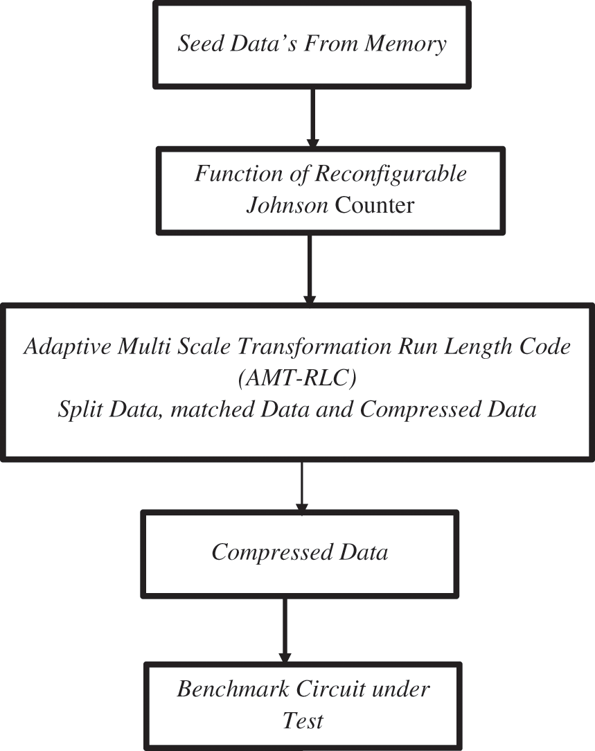
Figure 1: Block diagram of proposed system
3.1 Input Scan Operation of Test Data for Benchmark Circuit
Benchmark testing is the process of putting a part of a whole system through its paces to determine the application's display characteristics. The benchmark test is reproducible in the sense that the introductory assessments only vary by a few percent each time it is done. This enables single changes to be made to the program or setup, intending to determine if the appearance improves or degrades. Benchmarking may be used to combine parts of security testing. When benchmarking firewalls, a model is used. This necessitates the execution of system and customer loads, as well as security intrusions, against the section's presentation benchmark. Benchmarking goals are usually divided into two categories.
1. To test and tune the framework to arrive at a presentation necessity or Service Level Agreement (SLA). For this situation, a progression of benchmark tests is led related to iterative cycles of execution tuning.
Hardware Description Language (HDL) portrayal of the benchmark circuit is thought; at that point, the Fault has been infused into a unique circuit. Test Pattern is created by contrasting the yield of a unique and Fault circuit. Limited or decreased test vectors are taken and actualized in Field Programmable Gate Array (FPGA). The execution of the two algorithms is contrasted at last and has with the check, which has more effectiveness. This exploration work ISCAS 89’ circuit is chosen. This research work has chosen multiple stuck at Fault in the circuit. Stuck Fault may be stuck at “0” or “1” fault. Fig. 2 shows that stuck at “1” fault is injected at the Output of a9 (Output of NAND Gate).
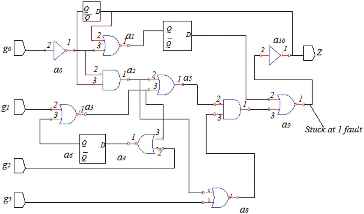
Figure 2: Stuck –at-1-fault (a9)
The S27 circuit, which belongs to the ISCAS 89’ benchmark circuit family, exhibits a stuck at “1” faults response, as shown in Tab. 1. It's a circuit with four data sources in a row: Two inverters, output, D-1ype flip failures eight gates (one AND, one NAND, two ORs, and four NORs) are shown in Fig. 2. Built-In-Self Test has been used to test the circuit. At first, defects are incorporated in the circuit's various bits. A similar procedure was followed for other ISCAS benchmark circuits for all nodes based on circuit capacity.
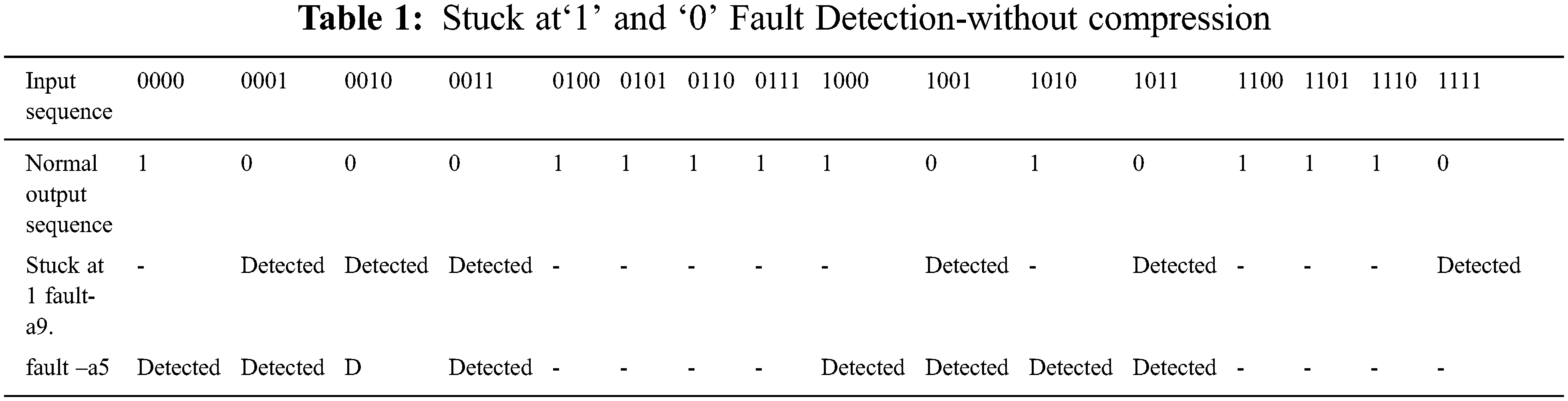
Fig. 3 shows that stuck at “0” fault is injected at a5 (input AND Gate, which is Common for the input of flip flop.) Tab. 1 shows the stuck at ‘0” faults reaction of the S27 circuit, which has a place with the ISCAS 89’ benchmark circuit family. It is a consecutive circuit with four data sources: Output, D-type flip failures, two inverters eight gates (1 ANDs + 1 NANDs + 2 ORs + 4 NORs), Shown in Fig. 3. The circuit has been tested by utilizing Built In-Self Test. At first, faults are embedded into the different bits of the circuit. The comparable method was followed for different ISCAS benchmark circuits for all nodes dependent on the circuit limit.
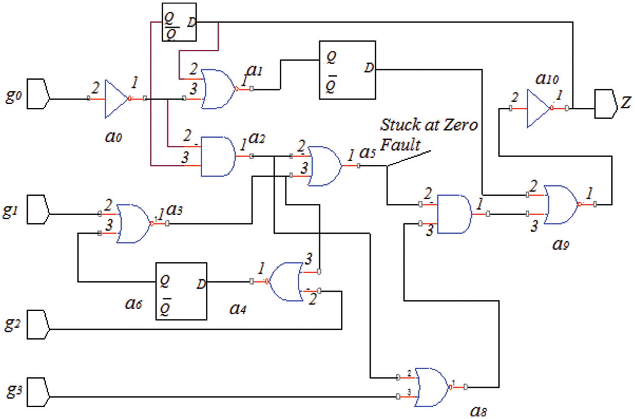
Figure 3: Stuck at fault at ‘0’ (a5)
3.2 Implementing Adaptive Multi-Scale Transformation Based Test Data Compression
When compared to the existing run-length code-based Linear Feedback Shift Register (LFSR) system, the proposed AMT-RLC logic reduces the test sequence. When comparing the AMT-RLC LFSR design to their trademark polynomial, this AMT-RLC logic, which is based on some rules, executes progressive bounces between states. The least amount of test information is stored in this AMT-RLC logic by picking the test information in the meaningless bits of the test design. Turning the heading of all the data flow between the latches indicated in the AMT-RLC logic tapping (XOR-ing 0th and 9th bit stored in 2ndposition) and taping the 10th and 6th contributions to the third lock executes the trade between the musical designs.
3.2.1 Implementation of Reconfigurable Johnson Counter
The Reconfigurable Johnson Counter (RJC) is made up of D-flip flops (D-FF) and a multiplexer that may be used to build unique test designs by selecting the activity method. CLK, enable (en), choice line, D-FF, and qn-1 then single yield as qn are the five information sources in the redesigned RJC structure. When the recommended RJC counter reaches the determination line, which is equivalent to logic “0,” it generates new test designs that employ tally activity to avoid back-to-back test groups. The current test sequence (seeds) is handled from memory if the choice line is set to logic “1.”. The implementation of RJC employing D-FFs XOR-ed with the feedback loop results in a new sequence of the test vector, as shown in Fig. 4.

Figure 4: Work flow structure of RJC
3.2.2 Test Data Split Using AMT-RLC
The underlying test data set TD, for a circuit with n test plans made by the Automatic Test Pattern Generation (ATPG) might be addressed by an n-tuple set, TD = TD1, TD2, TD3…, TDn, where the length of the ith test data, TDi, which comprises of 0 s, 1 s, and Xs, arranges the length of the output chain, ISC. Following the obtaining of the previously mentioned test data TD, the subsequent stage is for each TDi to be remembered for the length of the ISR. Thus, the mxn split enlightening test assortments become as follows:
Each Tdi is a subset of TDi, with ISR being the length of these subsets. As shown in Fig. 5, test information TD is composed of subsets of Tdi with cuts of m × n.

Figure 5: Test data split scheme
Because this length is connected to the hardware area overhead and compression ratio, the value of ISR must be determined by a specified standard. The following criteria can be used to predict the amount of compressed test information needed to determine a suitable ISR:
where CB (TD) = Sequence of Compressed data and TD, |TD| = Test data's Size
,1–,P-m..(,-d-i.,,-d-i+1.) = Probability of match between,-d-i.and, T-d-i+1.
The Probability of match can be updated as follows
Finally, the essential is that the words,-m .., T-d-i., T-d-i+1..] and m are both susceptible to ISR. In this approach, the compression ratio and hardware area overhead are associated with ISR. The effort required to obtain a complete region for good ISR is critical for better results. The overall functional block diagram of the multi-scale transformation operation is shown in Fig. 6. This block diagram has the complex operation of multiscale transformation-based test compression.

Figure 6: Block diagram of multi-scale transformation operation
The Mode Program includes test vectors and needs a SOC test. After agreeing to recover the non-trivial interesting test vectors in the decompression software, the test vectors were applied to each and the SOC to assess yield reactions. The test vectors are separated by 8 bits of the shipper's proportionate size, and the block size is determined by the total amount of vector bits. Bits of Block Assurance Within a couple of blocks, the entire number of blocks of the same size are dispersed. The number of bits per block in this work is an unambiguous 8-bit coding word. The quantity of blocks is brought out here, such as 8 = blocks equal to b = 0 b = 7. The decision has obstructed the remainder of the byte code and the ID bit scheme used for the encoded section is utilized in the tests, which rely on the presently limited high-request bits. An ID bit project controls which code words should be used in which sequence in the text. The decoder is employed with relative id bits to break the encoded bits, which are then encoded to id bits and byte code, with RLC connection to encoding test data. These results achieve improved memory for storing during significant test vectors in limited memory. The suggested AMT-RLC logic fulfills the matching sequence to increase efficiency. Two procedures should be taken to compress the split test data: 1) a forward X-filling for a larger number of matching test data sets, and 2) a backward X-filling for a smaller number of test data sets. Tdi, the unfilled split test data, is transformed into Tpi, a filled multiscale transformation, where Tpi={Tp(i−1)m+1,Tp(i−1)m+2,…,Tpim}; they are a subset of TP. Finally, the matching point is stored in the split variable T di and the filling variable T padded.
3.2.3 Function of Test Data Decompression
Fig. 7 depicts the suggested decompression architecture. The useful segment counter is not started with the RJC counter value when the value of the new seed is fed into the decompression architecture to count the total number of useful sections created per seed.

Figure 7: AMT-RLC-decompression architecture
A chain environment with RJC and AMT-RLC test code counters, relevant segment counters, and decoder circuitry in the proposed decompression architecture. Whenever a new seed is an input, many counters are utilized to compare and AMT-RLC the sequence, and the resulting seed is then supplied to the usable segments counter. After then, a new batch of seeds is picked for further processing. The Mode Select unit is utilized to determine the user segment's excellence. All values of the Segment Counter and RJC Counter are encoded for this assessment. The Mode Select unit receives the decoded output and uses it to drive the suggested test data AMT-RLC circuitry. The following are the steps in the Decompression algorithm. Encode Bits to take any of the ID pieces and blocks, the ID bits are decoded in the presence and 8-bit code word modified, counters until it is shown to be 1. 0 s. This scale is eventually used to check the number of 0 s associated with achieving the first uncompressed test vector that is moved over the code word and bytes. Achieve the first uncompressed bits on finding the overall thought of the emphasis on drawing. Tab. 2 discusses the test data sequence stuck at fault detection of the S27 benchmark circuit with the proposed system.

The Stuck at ‘1’ and Stuck at ‘0’ Fault Detection utilizing without compression sequence approach with three state method. When compared to the regular scan mode, the AMT-RLC approach detects all flaws. The stuck at ‘1’ fault is detected using a total of 64 bits in conventional scan mode, however, the planned tetra state AMT-RLC only needs 48 bits.
4 Simulation Results and Discussion
The simulation results and performance analysis of the suggested test data compression system are discussed in this section. Testing time and power consumption during the testing of SoCs are getting progressively significant with an expanding volume of test information in licensed innovation cores in SoCs. This work presented an Adaptive Multiscale transformation algorithm to decrease the scan-in power and test information volume utilizing the Adaptive Multiscale transformation-based run-length coding algorithm.
4.1 Simulation Results Analysis
The simulation result of standard output and stuck at Fault detected Output of S27 benchmark circuit is shown in Figs. 8a and 8b. The simulation result of the floor plan view is shown in Fig. 9.

Figure 8: Simulation output of S27

Figure 9: Simulation result of floor plan view–S27
4.2 Performance Analysis of Compression Ratio
The proposed Test data compression proportion can be assessed as
TD = Uncompressed Data
TS = Test Sets
TP = Skipped Data Separately
Tab. 3 compares the compression ratio performance of the proposed system to that of various other current approaches. Fig. 10 depicts a graphical analytical comparison of the compression ratio based on Tab. 3.

Figure 10: Test data compression ratio analysis

Fig. 10 compares the performance of the proposed Adaptive Multiscale transformation-based run-length coding technique to existing test data compression methods in terms of the Test Data Compression Ratio. When compared to standard approaches, this comparison clearly shows that the suggested method produces the best results. The suggested system's test data compression ratio in the S27 circuit was 68.85%.
4.3 Performance Analysis of Fault Coverage Ratio
The fault coverage of the proposed designs depends on the length of the test vector. The outcome of the test will depend on its fault coverage against functional faults, the proposed fault coverage ratio was estimated in Eq. (5) and fault coverage ratio comparison was shown in Tab. 4.

The performance analysis of the fault coverage ratio for the proposed system with some other existing methods is discussed in Tab. 4. Based on Tab. 4, the graphical analysis comparison of the fault coverage ratio is shown in Fig. 11.

Figure 11: Fault coverage ratio analysis
In terms of fault coverage ratio, Fig. 11 looks at the proposed Adaptive Multiscale transformation-based run-length coding with conventional compression methods. This examination plainly outlines that the proposed system conveys the greatest results when compared with common techniques. In the S27 circuit, the proposed method achieved a 98.65% compression ratio.
4.4 Performance Analysis of Area Overhead
The performance analysis of Area overhead for the proposed system with some other existing methods is discussed in Tab. 5. Based on Tab. 5, the graphical analysis comparison of area overhead is shown in Fig. 12.
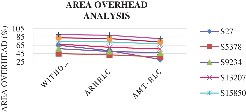
Figure 12: Performance of area overhead

Fig. 12 compares the proposed Adaptive Multiscale transformation-based run-length coding technique to existing test data compression methods in terms of area overhead consumption ratio. When compared to standard approaches, this comparison clearly shows that the suggested method produces the best results. The suggested system's area overhead consumption ratio in the S27 circuit for 31%.
4.5 Performance Analysis of Power Consumption
The performance analysis of power consumption for the proposed system with some other existing methods is discussed in Tab. 6. Based on Tab. 6 the graphical analysis comparison of power consumption is shown in Fig. 13.

Figure 13: Power consumption analysis
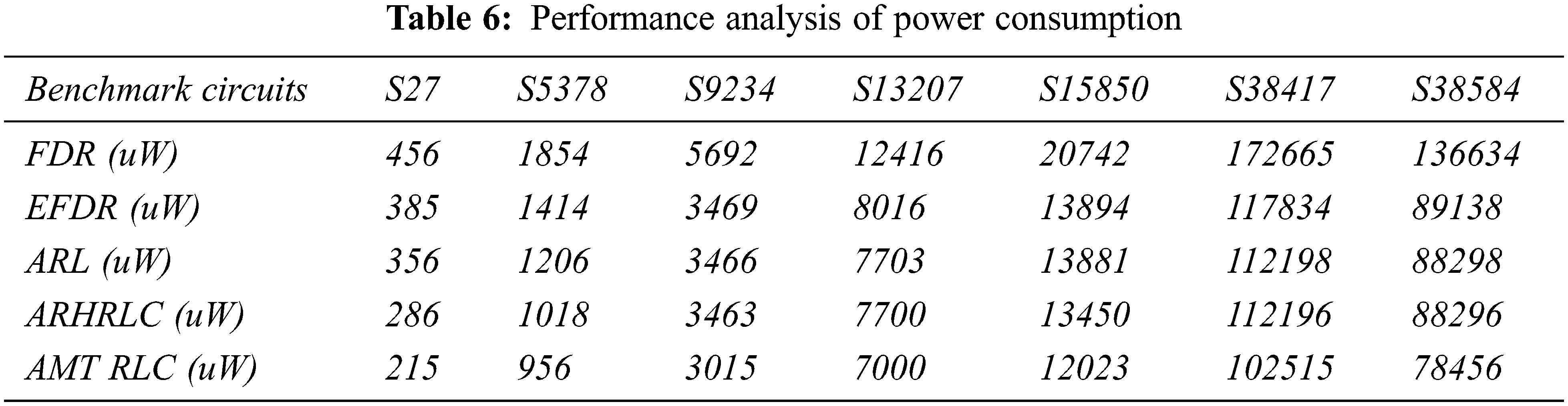
Fig. 13 compares the proposed Adaptive Multiscale transformation-based run-length coding technique to known test data compression methods in terms of power consumption ratio. When compared to standard approaches, this comparison clearly shows that the suggested method produces the best results. The suggested system's total power consumption ratio in the S27 circuit for 215uW.
4.6 Performance Analysis of Power Delay Product
The performance analysis of the power delay product for the proposed system with some other existing methods is discussed in Tab. 7. Based on Tab. 7, the graphical analysis comparison of the power delay product is shown in Fig. 14.

Figure 14: Performance analysis of power delay product

Fig. 14 compares the performance of the proposed Adaptive Multiscale transformation-based run-length coding technique with known test data compression methods in terms of power delay product. When compared to standard approaches, this comparison clearly shows that the suggested method produces the best results. The suggested system's total power delay product in the S27 circuit for just 9 s.
This work presented data compression techniques and a decompression system for testing ICAS89 benchmark circuits. The proposed approach utilizes Adaptive Multiscale transformation-based run-length coding and the inner output chain(s) of the code under test. It outperforms an ongoing compression technique based on Adaptive Multiscale Transformation-based run-length coding by a wide margin. An Adaptive Multiscale Transformation Run Length Code decreases the measure of test data that should be held on a tester and moved to each center of a System on a Chip (SOC) during a test. The data transfer speed between the tester and the SOC is a square when testing refined SOCs with a few centers to check how long the test can run. The proposed work keeps the tester in the SOC and the test vectors in a compressed memory structure. Because of its numerous qualities that reduce the test data volume, the Adaptive Multiscale Transformation Run Length Code is chosen for a core test vector system. These characteristics guarantee that the code words overhead is decoded utilizing a straightforward cell exhibit that occupies less room. The proposed realistic packs test data strikingly well, as per test results for the ISCAS 89 benchmarks. The findings also suggest that ATPG compaction isn't always necessary for preserving ATE memory and reducing testing time. The overall fault coverage and compression ratio of the proposed system are 95% and 70%.
Funding Statement: The authors received no specific funding for this study.
Conflicts of Interest: The authors declare that they have no conflicts of interest to report regarding the present study.
1. S. Mitra and D. Das, “An efficient VLSI test data compression scheme for circular scan architecture based on modified ant colony meta-heuristic,” Journal of Electron Test, vol. 36, pp. 327–342, 2020. [Google Scholar]
2. D. Gizopoulos, K. Roy, P. Girad, N. Nicolici and X. Wen, “Power-aware testing and test strategies for low power devices,” in Design, Automation and Test in Europe, DATE’08, IEEE Computer Society, Munich, Germany, pp. 1–14, 2008. [Google Scholar]
3. A. Asokan and J. P. Anita, “Multistage test data compression technique for VLSI circuits,” in Proc. Int. Conf. on Advanced Communication Control and Computing Technologies(ICACCCT), Ramanathapuram, India, pp. 65–68, 2016. [Google Scholar]
4. P. K. Biswal and S. Biswas, “On-line testing of digital VLSI circuits at register transfer level using high-level decision diagrams,” Microelectronics Journal, vol. 67, pp. 88–100, 2017. [Google Scholar]
5. N. A. Touba, “Survey of test vector compression techniques,” IEEE Design and Test of Computers, vol. 23, no. 4, pp. 294–303, 2006. [Google Scholar]
6. S. Lenin Babu and N. S. MurtiSarma, “Automatic test pattern generation-A survey,” in Proc. Int. Conf. on Energy, Communication, Data Analytics and Soft Computing (ICECDS), Chennai, India, pp. 3012–3017, 2018. [Google Scholar]
7. P. S. Dilip, G. R. Somanathan and R. Bhakthavatchalu, “Reseeding LFSR for test pattern generation,” in Proc. Int. Conf. on Communication and Signal Processing (ICCSP), Chennai, India, pp. 0921–0925, 2019. [Google Scholar]
8. N. V. Teja and E. Prabhu, “Test pattern generation using NLFSR for detecting single stuck–at faults,” in Proc. Int. Conf. on Communication and Signal Processing (ICCSP), Chennai, India, pp. 0716–0720, 2019. [Google Scholar]
9. S., Sivananthamand, S. B. Aravind, B. Ramki and P. Mallick, “Test data compression with alternating equal-run-length coding,” International Journal of Engineering and Technology, vol. 7, no. 4, pp. 1089, 2018. http://dx.doi.org/10.14419/ijet.v7i4.10.27925. [Google Scholar]
10. G. N. Balaji, S. C. Pandian and D. Rajesh, “Fast test pattern generator using ATALANTA M 2.0,”Asian Journal of Research in Social Science and Humanities, vol. 7, no. 2, pp. 721–729, 2017. [Google Scholar]
11. U. S. Mehta, K. S. Dasgupta and M. D. Niranjan, “Run-length-based test data compression techniques: How far from entropy and power bounds?—A survey,” VLSI Design, vol. 2010, no. 670476, pp. 1–10, 2010. [Google Scholar]
12. K. R. Krishnapriya and M. A. Muthiah, “An efficient test data compression based on iterative XOR matrix computation,” ARPN Journal of Engineering and Applied Sciences, vol. 11, no. 9, pp. 1–14, 2006. [Google Scholar]
13. J. Lee and N. A. Touba, “LFSR-Reseeding scheme achieving low-power dissipation during the test,” IEEE Transactions Computer Aided Design of Integrated Circuits and System, vol. 26, no. 2, pp. 396–401, 2007. [Google Scholar]
14. N. A. Touba, “Survey of test vector compression techniques,” IEEE Design and Test of Computers, vol. 23, no. 4, pp. 294–303, 2006. [Google Scholar]
15. P. T. Gonciari, B. M. Al-Hashimi and N. Nicolici, “Variable-length input huffman coding for system-on-a-chip test,” IEEE Transactions on Computer-Aided Design of Integrated Circuits and Systems, vol. 22, no. 6, pp. 783–796, 2003. [Google Scholar]
16. A. Jas, J. Ghosh-Dastidar, M. E. Ng and N. A. Touba, “An efficient test vector compression scheme using selective huffman coding,” IEEE Transaction on Computer Aided Design of Integrated Circuits and Systems, vol. 22, no. 6, pp. 797–806, 2003. [Google Scholar]
17. X. Kavousianos, E. Kalligeros and D. Nikolos, “Optimal selective huffman coding for test-data compression computers,” IEEE Transactions, vol. 56, no. 8, pp. 1146–1152, 2007. [Google Scholar]
18. A. Chandra and K. Chakrabarty, “Test data compression and test resource partitioning for system-on-a-chip using frequency-directed run-length (FDR) codes,” IEEE Transactions on Computers, vol. 52, no. 8, pp. 1076–1088, 2003. [Google Scholar]
19. E. H. Aiman, “Test data compression for system-on-a-chip using extended frequency-directed run-length code,” IET Computers and Digital Techniques, vol. 2, no. 3, pp. 155–163, 2008. [Google Scholar]
20. A. Chandra and K. Chakrabarty, “Reduction of SOC test data volume, scan power, and testing time using alternating run-length codes,” in Proc. 2002 Design Automation Conf. (IEEE Cat. No.02CH37324), New Orleans, LA, USA, pp. 673–678, 2002. [Google Scholar]
21. X. Ruan and R. Katti, “An efficient data-independent technique for compressing test vectors in systems-on-a-chip,” in IEEE Computer Society Annual Symp. on Emerging VLSI Technologies and Architectures (ISVLSI'06), Karlsruhe, Germany, pp. 25–41, 2006. [Google Scholar]
22. H. Yuan, J. Mei, H. Song and K. Guo, “Test data compression for system-on-a-chip using count compatible pattern run-length coding,” Journal of Electronic Testing, vol. 30, no. 2, pp. 237–242, 2014. [Google Scholar]
23. W. Zhan and A. El-Maleh, “A new collaborative scheme of test vector compression based on equal-run-length coding,” in Proc. of the 2009 13th Int. Conf. on Computer Supported Cooperative Work in Design, Santiago, Chile, pp. 21–25, 2009. [Google Scholar]
24. C. H. Chang, L. J. Lee, W. D. Tseng and R. B. Lin, “2n pattern run-length for test data compression,” in Proc. 2010 Int. Computer Symposium (ICS2010), IEEE, Tainan, Taiwan, pp. 562–567, 2010. [Google Scholar]
25. A. H. El-Maleh, “Efficient test compression technique based on block merging,” IET Computers and Digital Techniques, vol. 2, no. 5, pp. 327–335, 2008. [Google Scholar]
26. M. Tehranipoor and S. Nourani, “Nine-coded compression technique for testing embedded cores in SOCs,” IEEE Transactions on Very Large Scale Integration (VLSI) Systems, vol. 13, no. 6, pp. 719–731, 2005. [Google Scholar]
27. T. B. Wu, H. Z. Liu and P. X. Liu, “Efficient test compression technique for soc based on block merging and eight coding,” Journal of Electronic Testing: Theory and Applications, vol. 29, no. 6, pp. 849–859, 2013. [Google Scholar]
28. H. Yuan, J. Mei, X. Sun, K. T. Cheng and K. Guo, “A power-efficient test data compression method on count compatible prl coding,” Journal of Circuits, Systems, and Computers, vol. 24, no. 6, pp. 1550084–17, 2015. [Google Scholar]
29. S. Sivanantham, M. Padmavathy, G. Gopakumar, P. S. Mallick and J. R. P. Perinbam, “Enhancement of test data compression with multistage encoding,” Integration, vol. 47, no. 4, pp. 499–509, 2014. [Google Scholar]
30. A. Chandra and K. A. Chakrabarty, “A unified approach to reduce SOC test data volume, scan power, and testing time,” IEEE Transactions on Computer-Aided Design of Integrated Circuits and Systems, vol. 22, no. 3, pp. 352–363, 2003. [Google Scholar]
31. K. Radhika and D. Geetha, “Augmented recurrence hopping based Run-length coding for test data compression applications,” Wireless Personal Communications, vol. 102, no. 8, pp. 1–21, 2018. [Google Scholar]
 | This work is licensed under a Creative Commons Attribution 4.0 International License, which permits unrestricted use, distribution, and reproduction in any medium, provided the original work is properly cited. |