DOI:10.32604/iasc.2023.024179
| Intelligent Automation & Soft Computing DOI:10.32604/iasc.2023.024179 | |
| Article |
Machine Learning Controller for DFIG Based Wind Conversion System
1Department of Electronics and Communication Engineering, Amrita College of Engineering and Technology, Nagercoil, 629002, India
2Department of Electrical and Electronics Engineering, Ponjesly College of Engineering, Nagercoil, 629002, India
*Corresponding Author: P. Srinivasan. Email: srinivasanpaul@gmail.com
Received: 08 October 2021; Accepted: 27 February 2022
Abstract: Renewable energy production plays a major role in satisfying electricity demand. Wind power conversion is one of the most popular renewable energy sources compared to other sources. Wind energy conversion has two major types of generators such as the Permanent Magnet Synchronous Generator (PMSG) and the Doubly Fed Induction Generator (DFIG). The maximum power tracking algorithm is a crucial controller, a wind energy conversion system for generating maximum power in different wind speed conditions. In this article, the DFIG wind energy conversion system was developed in Matrix Laboratory (MATLAB) and designed a machine learning (ML) algorithm for the rotor and grid side converter. The ML algorithm has been developed and trained in a MATLAB environment. There are two types of learning algorithms such as supervised and unsupervised learning. In this research supervised learning is used to power the neural networks and analysis is made for various hidden layers and activation functions. Simulation results are assessed to demonstrate the efficiency of the proposed system.
Keywords: Doubly fed induction generator; machine learning; convertors; generators; activation function
Wind power generation based on the doubly-fed induction generator (DFIG) has gained growing esteem due to numerous advantages, including smaller converters rating around 30% of the generator rating, variable speed and four-quadrant, active and reactive power operation capabilities, lower converter cost, and power losses compared with the fixed-speed induction generators or synchronous generators with full-sized converters [1]. Over the past few years, many researchers have carried out extensive research for DFIG wind turbine generator to enable frequency regulation and frequency support capability [2]. In DFIG, Sliding Mode Control (SMC) method can be used to control the stator and rotor currents with respect to rotor speed [3]. A number of new control strategies were examined to improve the operational performance of the DFIG. In addition a proportional derivative regulator (PD) is added to the Rotor Side converter (RSC) DFIG power [4] and the output varies for the changing error [5]. Kinetic energy is utilized to support grid frequency from serious actuations [6], but the medication of power reference will lead to severe frequency secondary drop [7], which is determined by the sudden loss of active power support since DFIG rotor speed has reached its permitted limit [8]. In the traditional control scheme of DFIG systems, two proportional-integral (PI) controllers were applied in the current control loop [9]. On the basis of the decomposition of positive and negative sequence components in and out frames are created [10]. The current controllers were implemented in the positive and negative synchronous reference frames, respectively [11]. Due to timing and control errors introduced through the decomposition of positive and negative components of the sequence, the dynamic performance and stability of the system could be degraded [12]. Considering the consumer loads that are located at a considerable distance away from the wind farm, a long-distance transmission line will be needed to link the wind farm and the grid [13]. The overall network reactance increases for long-distance transmission lines resulting in a reduction in power transfer capacity leading to voltage drop and hence the power factor of the system decreases which is explained using Eq. (1).
where P is the actual power flow through-line,
i) In order to achieve the specified control objectives in the non-ideal grid condition, the fundamental, negative and harmonic components of the grid tension must be extracted. The extraction process would use numerous notch and low pass filters; therefore, phase delay and control error would be unavoidable [15].
ii) In order to implement the different control targets by employing voltage oriented control (VOC) or direct power control (DPC) strategy, the control reference calculation of rotor current in VOC or active/reactive power in DPC is always complicated and time-consuming. Furthermore, the deviation between the DFIG parameters and the fundamental, negative and harmonic change in the grid voltage would also affect the accuracy of the baseline calculation of control target [16].
iii) Some DFIG characteristics, such as the lack of short circuit capacity, low inertia, and uncertainty of damping, are likely detrimental to overall system voltage stability, frequency stability, and oscillation damping in actual operation [17].
iv) To achieve a smooth active power output of the DFIG system to the grid, the conventional control strategy, similar as, would allow the existence of active power pulsed in the RSC, while the grid side converter (GSC) is controlled to generate the opposite active power pulsation of the same quantity as RSC [18].
v) This paper proposes the machine learning algorithm strategy for both DFIG’s RSC and GSC under the unbalanced grid voltage, which can achieve the different control targets for the overall DFIG system [19].
The following are the core contributions of this paper: Section 2 explains the design of DFIG based wind energy conversion system. Section 3 explains the Machine learning algorithm with the simulation using the MATLAB environment. Section 4 draws several conclusions.
The doubly-fed induction generator (DFIG) system is a popular system in which the power electronic interface controls the rotor currents to achieve the variable speed necessary for maximum energy capture in variable winds. As power electronics only process the rotor power, typically less than 25% of the overall output power, the DFIG offers the advantages of speed control with reduced cost and power losses. In the steady-state analysis, the derivatives of flow linkages are equal to zero, since the system is stable. In contrast, derivatives of flow connections are taken into account for the dynamic analysis. The magnetization circuit is represented by the shunt inductance Lm, which is calculated without taking into account R0. The voltages of the stator and rotor are converted from the back frame to the synchronously spinning direct quadrature (DQ) frame, and they are defined by Eqs. (2)–(5).
where
The modified voltage equations can be represented as Eq. (6)
The situation and organize matrix of the DFIGs can be expressed as
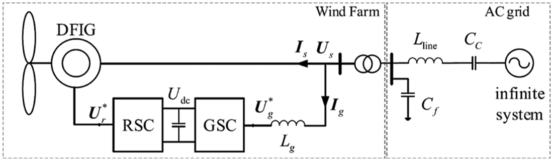
Figure 1: Block diagram
The DFIG wind energy system features two main controllers such as the grid-side converter controller and the rotor-side converter controller. Both converters play important roles in wind energy systems based on the DFIG. The grid side converter has two major controllers which are the voltage regulator and current regulator. The DFIG-based 1.5 MW wind energy conversion system was simulated in the MATLAB environment as shown in Fig. 2.
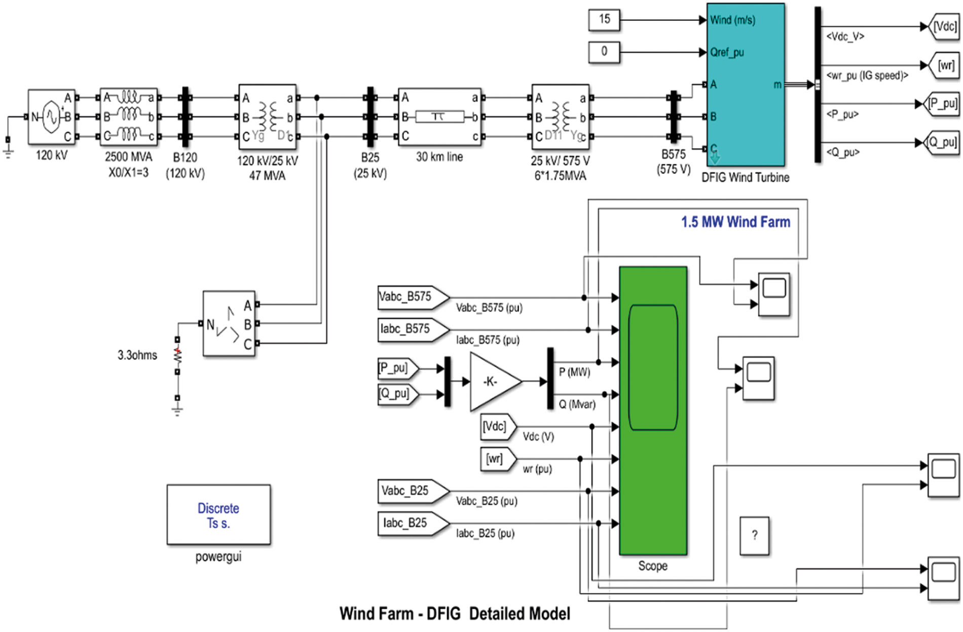
Figure 2: A simulation model of DFIG based wind energy system
The voltage and current regulator have been developed in MATLAB and the controller by Machine learning algorithm is shown in Figs. 3 and 4.
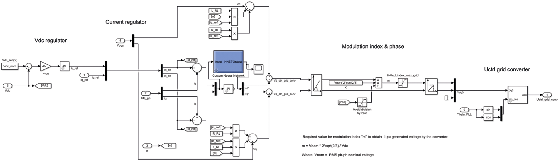
Figure 3: Machine learning-based grid side converter control system
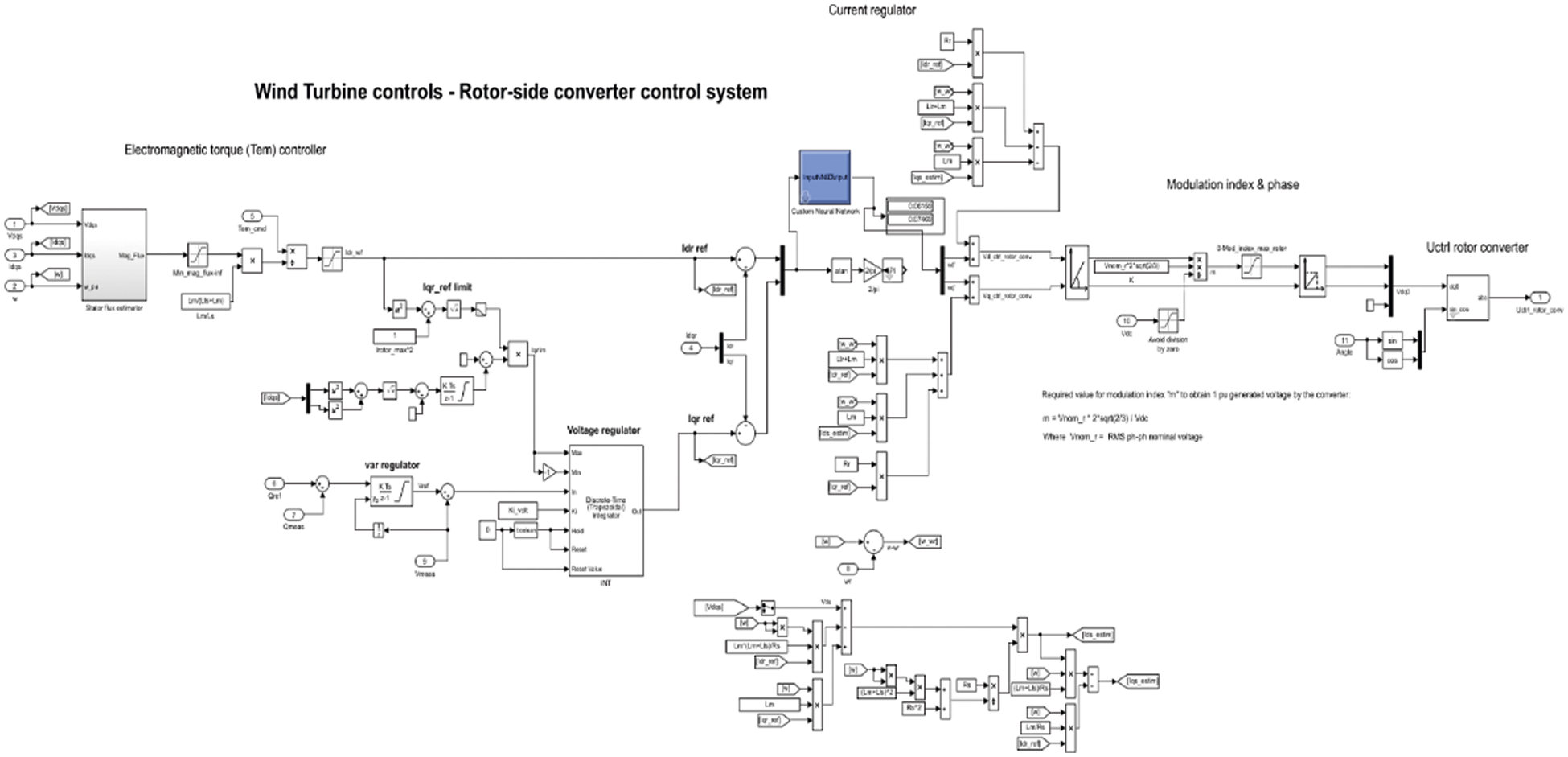
Figure 4: Machine learning-based rotor side converter control system
3 Machine Learning Algorithm Simulation and Results
The ML algorithm is a very powerful tool for the design and management of nonlinear problems. The ML algorithm treats machine learning by using input and output data collection and then predicting future values. These are two types of learning algorithms commonly used for engineering applications such as supervised learning and unsupervised learning. In this research work, supervised learning was used for power neural networks and analyses with various hidden layer sizes and activation functions. In the ML representation of the DFIG model, the electromagnetic torque of wind turbine generator (WTG) is obtained by sending feedback signals to the control system. The DFIG is controlled by the signals (−g) from the wind turbine, regulated voltages (
3.1 Two Hidden Layers–Rotor Side
This model has been modeled for rotor side converter control and it has two hidden layers used to develop a machine learning algorithm with a sigmoidal activation function. The feedforward network has 2 input layers such as direct axis current (Id) and quadrant axis current (Iq). Two hidden layers are developed with 20 and 25 neurons and it is connected to output layers which have two output parameters such as direct axis voltage Vd and quadrant axis voltage (Vq) as shown in Fig. 5.

Figure 5: Rotor side controller using two hidden Machine learning networks
Then network has been trained been observed data collected from the simulation model and it is feed into ML algorithm to provide training of feedforward network. The network best performance and validation check data are presented in Figs. 6 and 7.
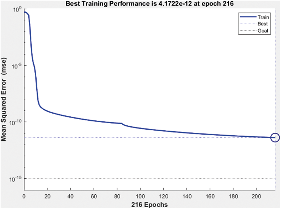
Figure 6: Best performance of machine learning network
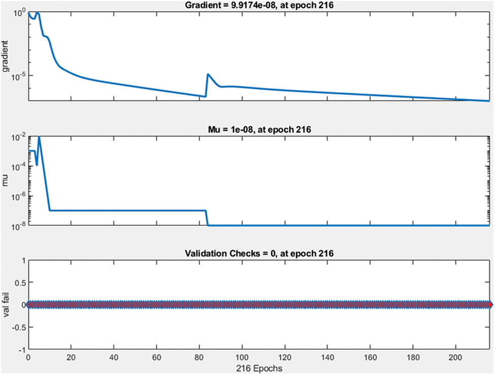
Figure 7: Validation check data
The best performance of the network model is 4.1722 e−12 at epoch 216 and gradient 9.917e−4 at disclose at the submission stage any restrictions on the availability of materials or information.
3.2 Two Hidden Layers–Grid Side
This model has been modeled for grid side converter control and it has two hidden layers used to develop a machine learning algorithm with a sigmoidal activation function. The feedforward network has 2 input layers such as direct axis current (Id) and quadrant axis current (Iq). Two hidden layers are developed with 20 and 25 neurons and it is connected to output layers which have two output parameters such as direct axis voltage Vd and quadrant axis voltage Vq as shown in Fig. 8.
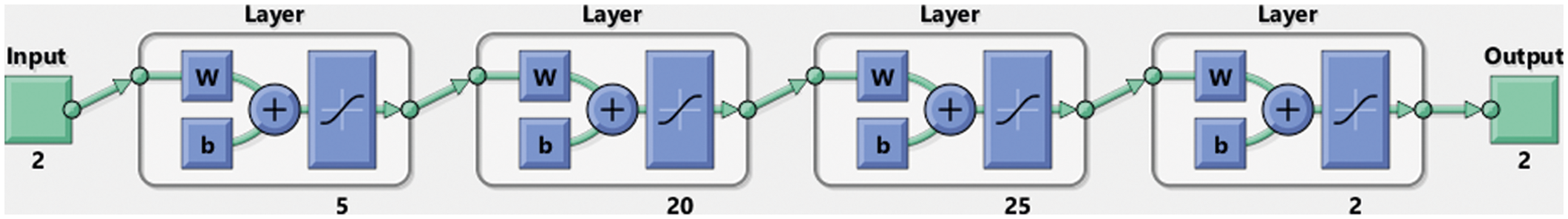
Figure 8: Grid side controller using two hidden machine learning networks
Then network has been trained been observed data collected from the simulation model and it is fed into ML algorithm to provide training of feedforward network. The network best performance and validation check data are presented in Figs. 9 and 10.
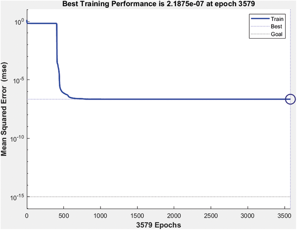
Figure 9: Best performance of machine learning network
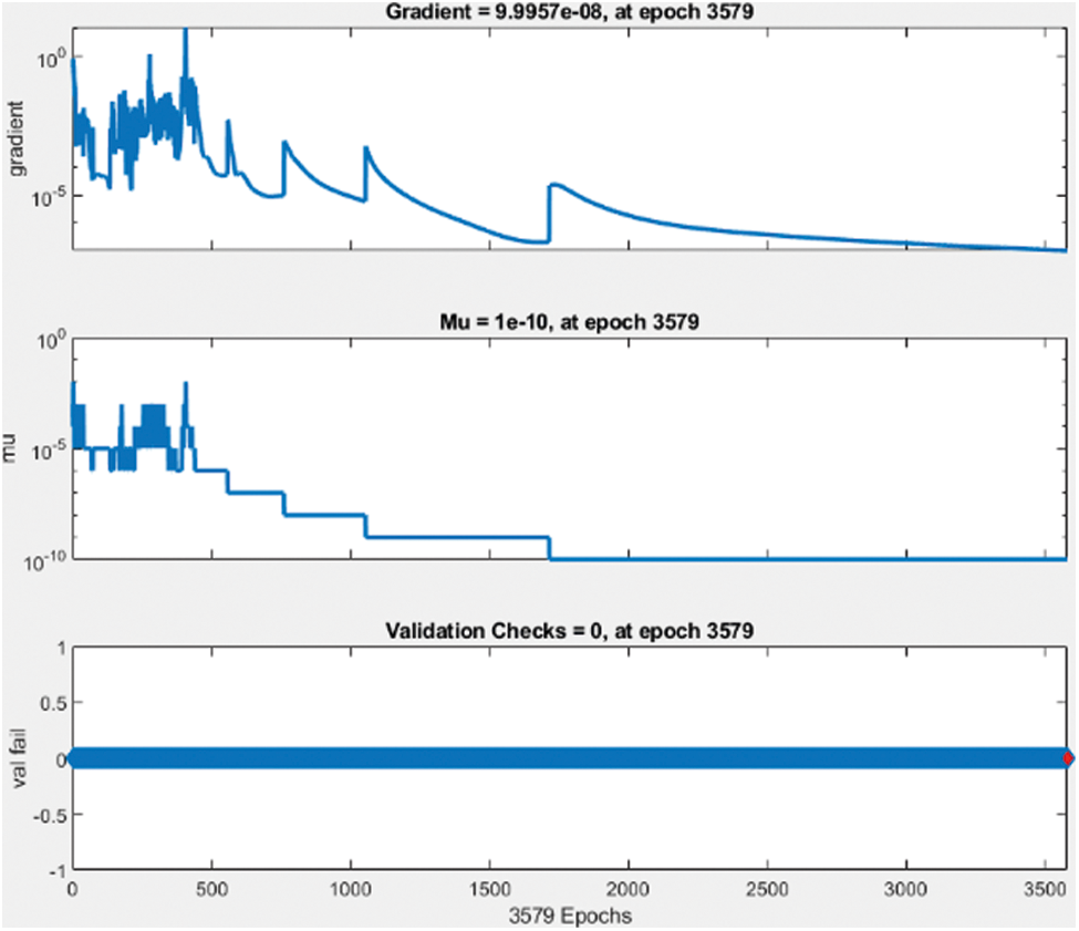
Figure 10: Validation check data
The best performance of the network model is 2.1875 e−7 at epoch 3579 and gradient 9.9957 e−8 at epoch 3579. After the design and training of the machine learning algorithm, the Simulink model has been developed in MATLAB environment. This Simulink controller block has been used for the grid side converter controller and rotor side converter controller. The proposed DFIG based wind energy system has been simulated for up to 7 s. The simulation results are presented for the real and reactive power of DFIG based wind energy system with the grid as shown in Fig. 11.
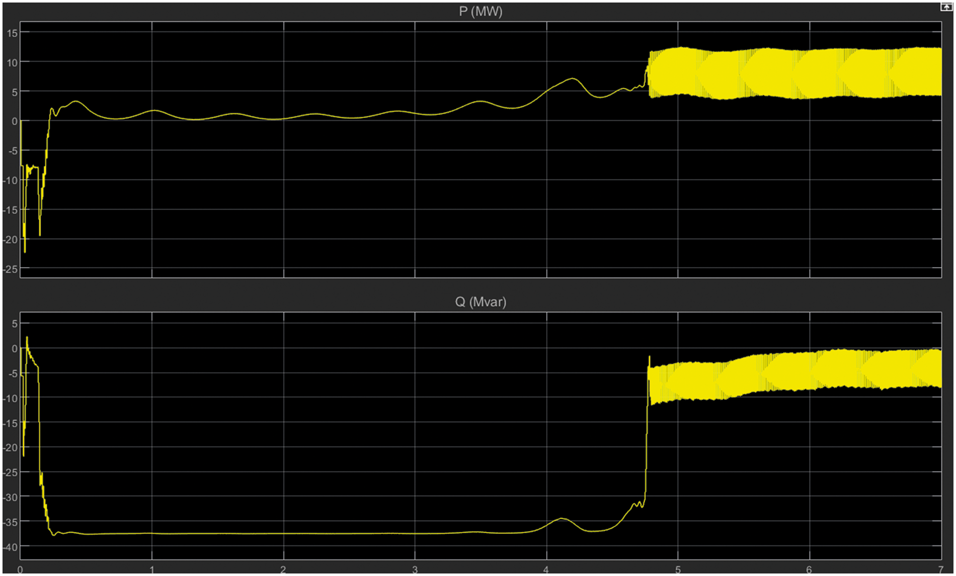
Figure 11: Real and reactive power
Fig. 12 presents the details of the direct current (DC) voltage of the converter side. Based on the simulation results there are many disturbances and fluctuations in the waveform.
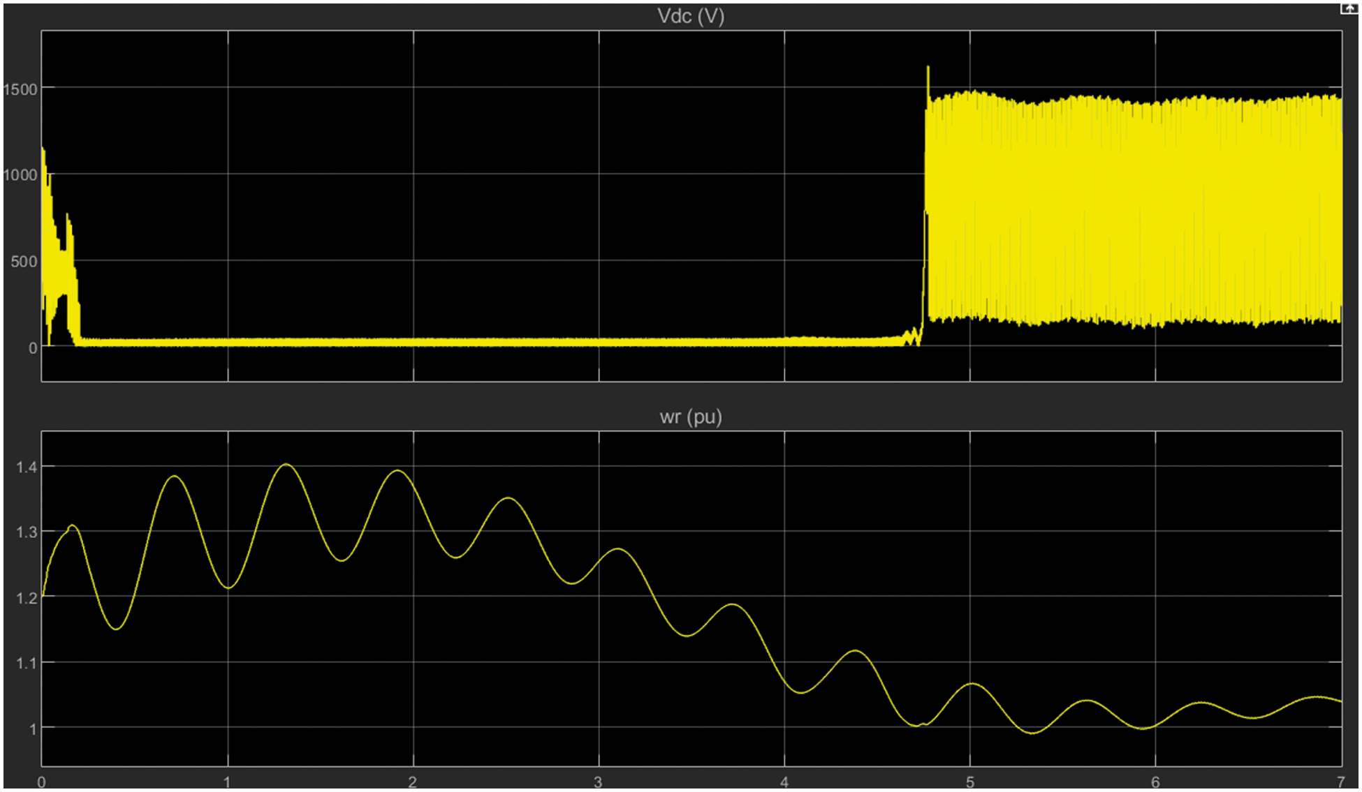
Figure 12: DC voltage
3.3 Four Hidden Layers–Grid Side
This model has been modeled for the grid-side converter control and has two hidden layers used to develop a machine learning algorithm with a sigmoid activation function. The feedforward network has 2 input layers such as direct axis current (Id) and quadrant axis current (Iq). Four hidden layers are developed with 20, 30, 35 and 25 neurons, respectively, and it is connected to output layers which have two output parameters such as direct axis voltage Vd and quadrant axis voltage Vq. Then the network was formed was observed the data collected from the simulation model and it is input into the ML algorithm to provide the formation of the feedback network. The best performance control and network validation data are presented in Figs. 13 and 14.
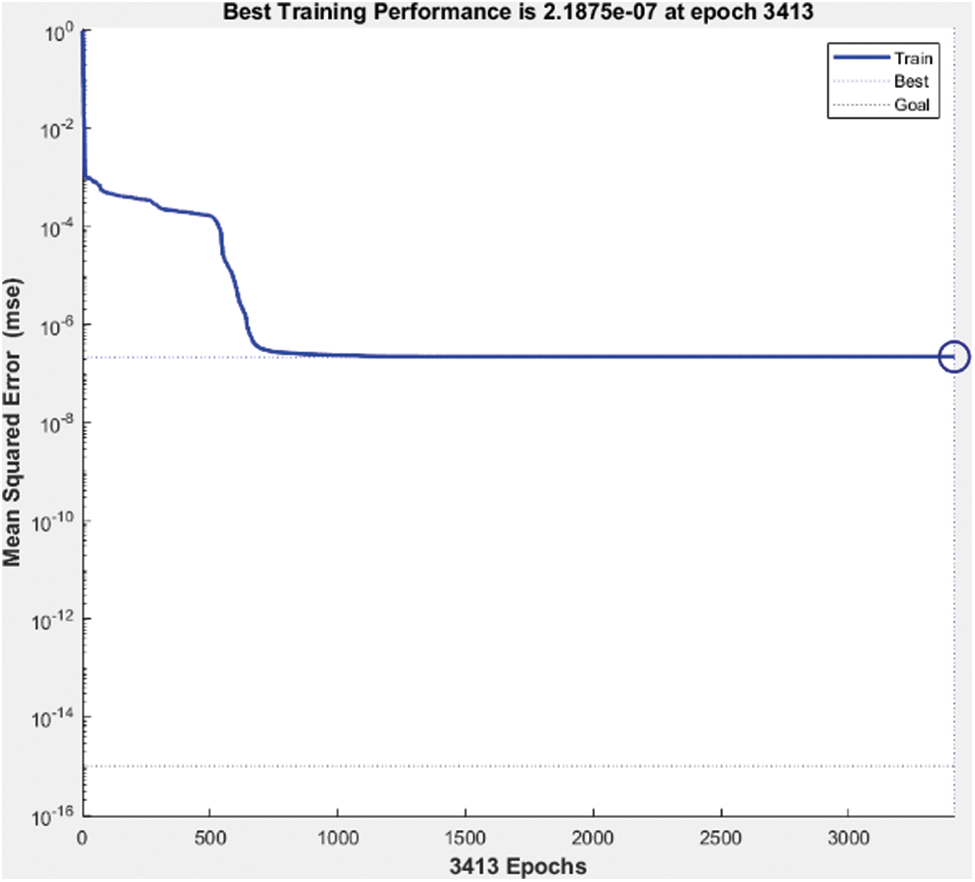
Figure 13: Best performance of machine learning network
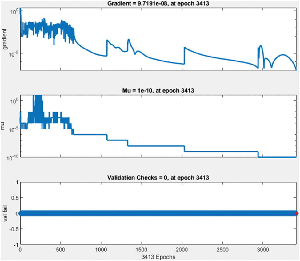
Figure 14: Validation check data
The best performance of the network model is 2.1875 e−7 at epoch 3413 and gradient 9.719e−8 at epoch 3413.
3.4 Four Hidden Layers–Rotor Side
This model has been modeled for the rotor side converter control and it has two hidden layers used to develop a machine learning algorithm with a sigmoid activation function. The feedforward network has 2 input layers such as direct axis current (Id) and quadrant axis current (Iq). Four hidden layers are developed with 20 30, 35 and 25 neurons, respectively, and it is connected to output layers which have two output parameters such as direct axis voltage Vd and quadrant axis voltage Vq. Then network has been trained been observed data collected from the simulation model and it is fed into ML algorithm to provide training of feedforward network. The best performance control and network validation data are presented in Figs. 15 and 16.
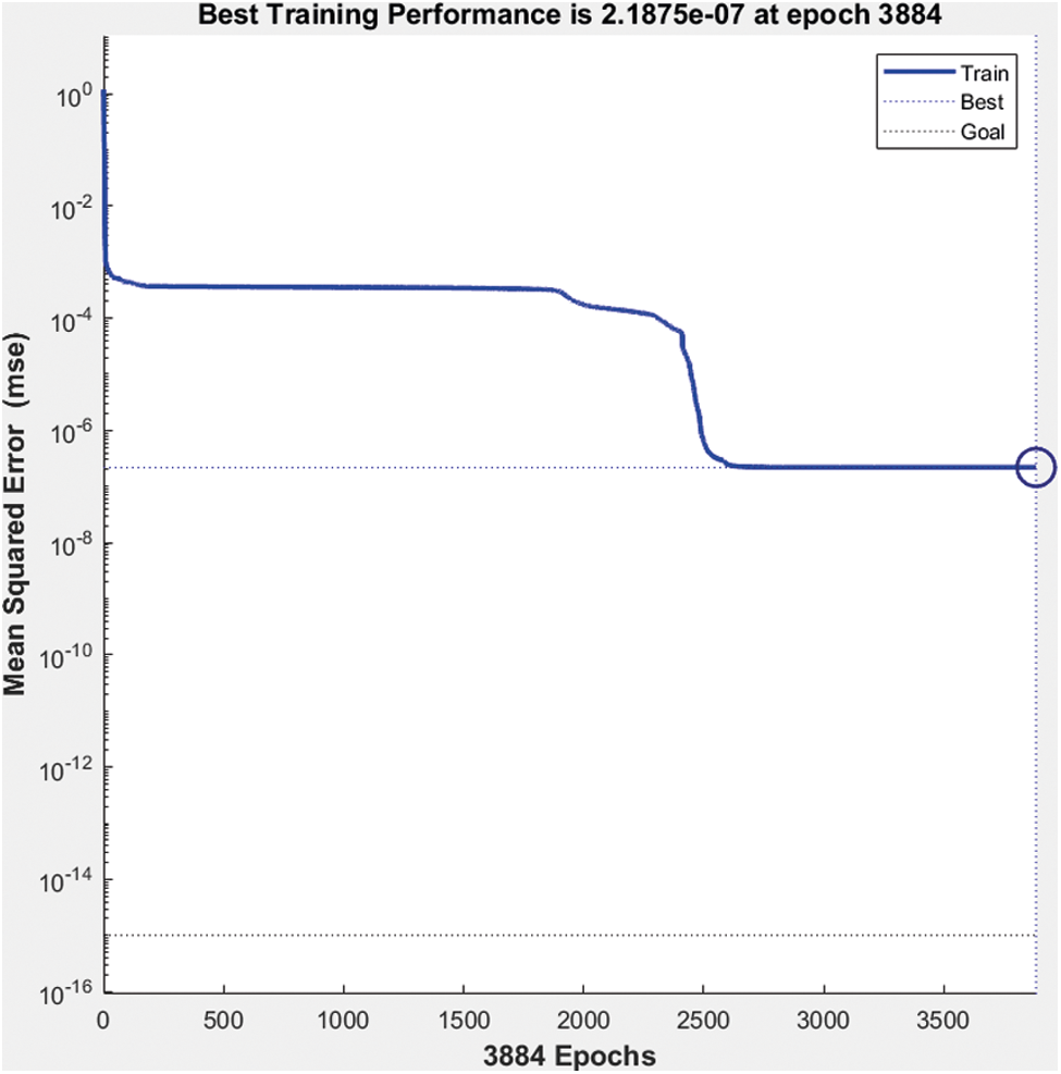
Figure 15: Best performance of machine learning network
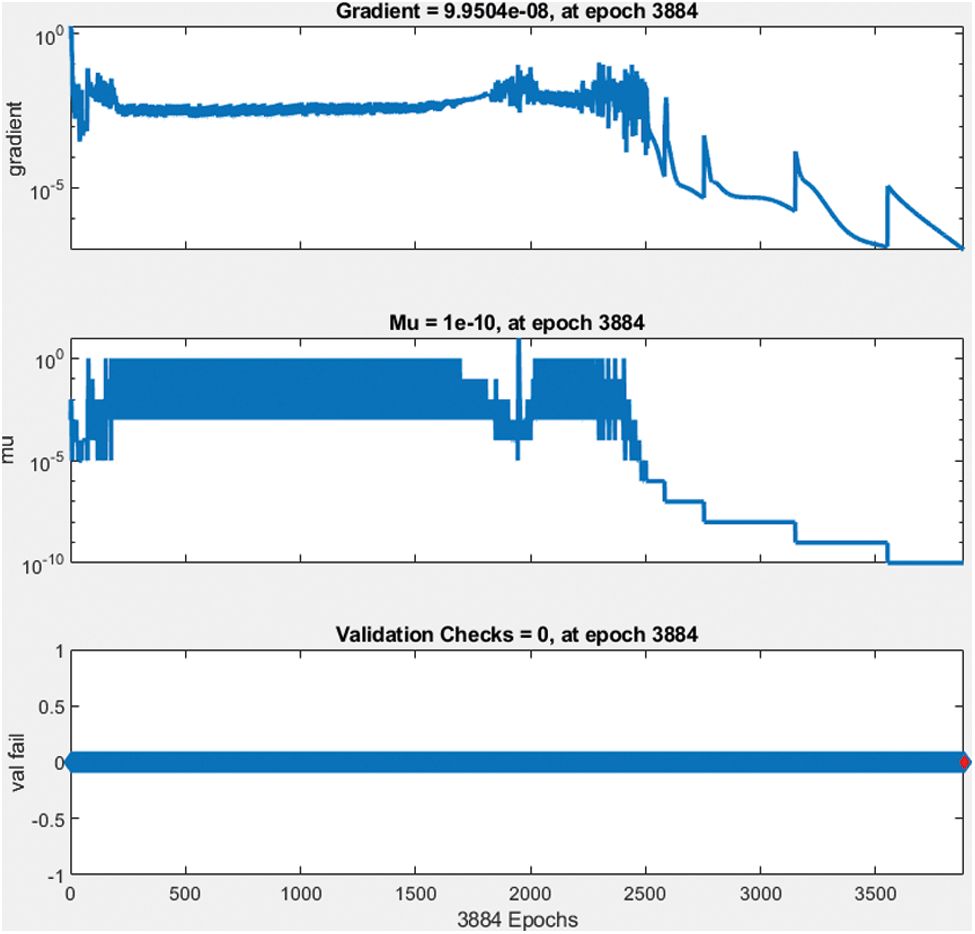
Figure 16: Validation check data
The best performance of the network model is 2.1875 e−7 at epoch 3884 and gradient 9.9504 e-8 at epoch 3384.
3.5 Four Hidden Layers with Linear Activation Function – Rotor Side
This model has been modeled for rotor side converter control and it has two hidden layers used to develop a machine learning algorithm with a linear activation function. The feedforward network has 2 input layers such as direct axis current (Id) and quadrant axis current (Iq). Four hidden layers are developed with 20, 30, 35 and 25 neurons respectively and it is connected to output layers which have two output parameters such as direct axis voltage Vd and quadrant axis voltage Vq as shown in Fig. 17.

Figure 17: Rotor side controller using two hidden machine learning networks
Then network has been trained been observed data collected from the simulation model and it is fed into ML algorithm to provide training of feedforward network. The network best performance and validation check data are presented in Figs. 18 and 19.
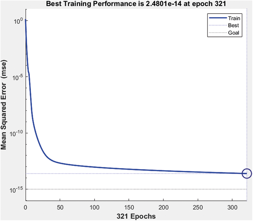
Figure 18: Best performance of machine learning network
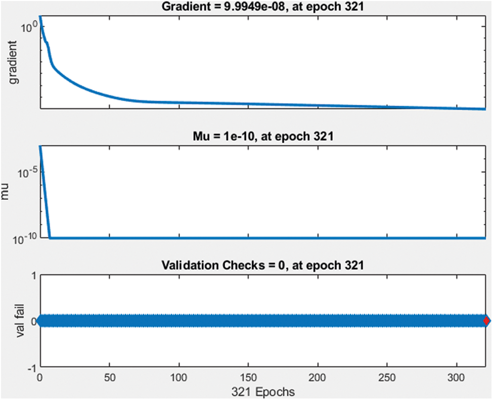
Figure 19: Validation check data
The best performance of the network model is 2.4801 e−14 at epoch 321 and gradient 9.9949 e−8 at epoch 321. Compared to the previous network size and activation function proposed network and activation model provide good results.
3.6 Four Hidden Layers with Linear Activation Function
This model has been modeled for grid side converter control and it has two hidden layers used to develop a machine learning algorithm with a sigmoidal activation function. The feedforward network has 2 input layers such as direct axis current (Id) and quadrant axis current (Iq). Four hidden layers are developed with 20, 30, 35 and 25 neurons respectively and it is connected to output layers which have two output parameters such as direct axis voltage Vd and quadrant axis voltage Vq as shown in Fig. 20.
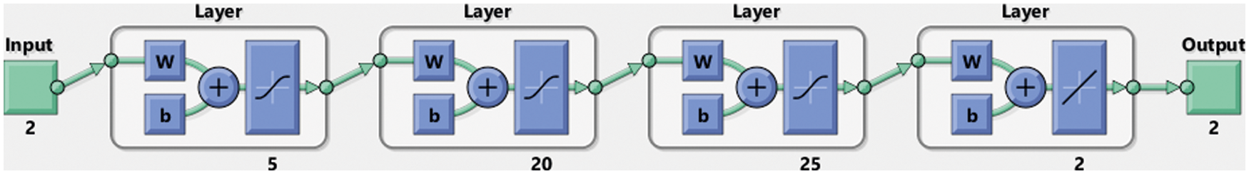
Figure 20: Grid side controller using two hidden machine learning networks
Then network has been trained been observed data collected from the simulation model and it is fed into ML algorithm to provide training of feedforward network. The network best performance and validation check data are presented in Figs. 21 and 22.
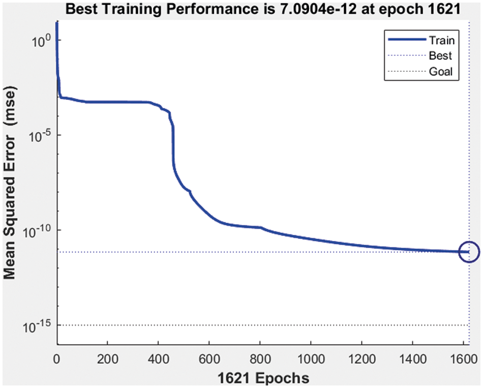
Figure 21: Best performance of machine learning network
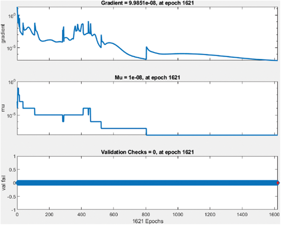
Figure 22: Validation check data
The best performance of the network model is 7.090 e−12 at epoch 1621 and gradient 9.9851 e−8 at epoch 1621. Compared to the previous network size and sigmoidal activation function the proposed 4 hidden layer networks and linear activation function provide better performance.
Various wind speeds and compensation levels are shown in Tab. 1, which correspond to modes with super synchronous frequencies higher than 50 hertz (198 Hz). The Eigenvalues (_1 _2) are associated with the super synchronous mode of oscillations, which has frequencies that are higher than the system frequency. Unlike other modes of operation, these modes are always stable and do not become unstable when the operating circumstances vary. Considering that the mechanical system frequencies are always below 50 Hz, the super synchronous frequencies are never in sync with the mechanical system frequencies. As a result, these modes are never unstable. Because of the differences in wind speeds and correction levels, the frequency of these modes remains unchanged. Increasing wind velocity has a smaller effect on the real portion of the Eigenvalues than decreasing wind velocity.
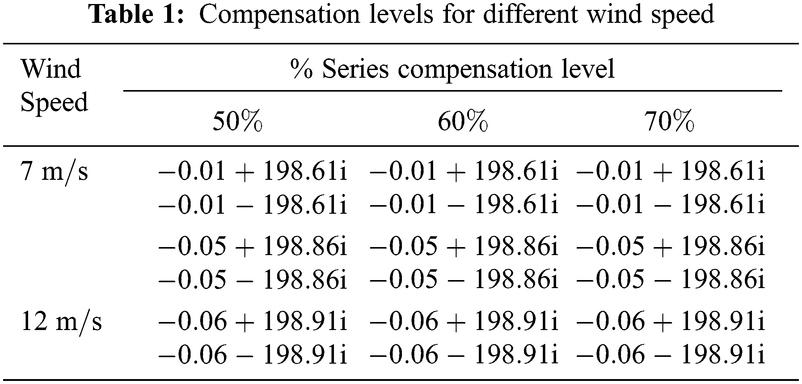
Variations in the operating circumstances have an important impact on the stability of the system in question. Due to the possibility of negative consequences caused by the existence of low-frequency modes, it is necessary to investigate them using the tiny indicator firmness examination using the Eigen cost method. The Eigen assessment examination is agreed out for a variety of wind speed circumstances, compensation levels, and stiffness coefficients, among other parameters. The value of the stiffness coefficient varies as a result of the age of the machine, and this may have a significant effect on the machine’s stability.
After designing and training the machine learning algorithm the Simulink model has been developed in MATLAB environment. This Simulink controller block has been used for the grid side converter controller and rotor side converter controller. The proposed DFIG based wind energy system has been simulated for a period of 7 s. The simulation results are presented for the real and reactive power of DFIG based wind energy system with the grid as shown in Fig. 23.
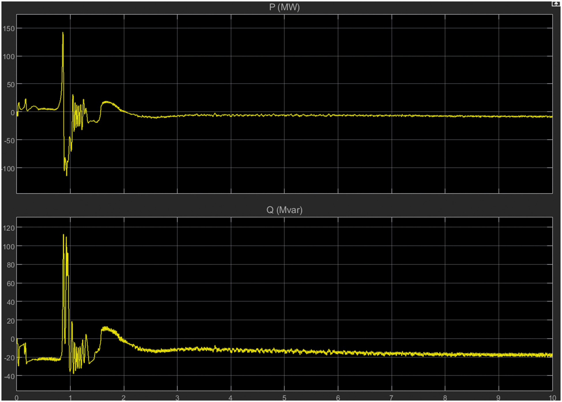
Figure 23: Real and reactive power
Fig. 24 presents the details of the DC voltage of the converter side. Based on the simulation results there are many disturbances and fluctuations in the waveform. Hence the next section the machine learning algorithm network hidden layer size remains the same and changes the activation function from sigmoidal to linear activation function.
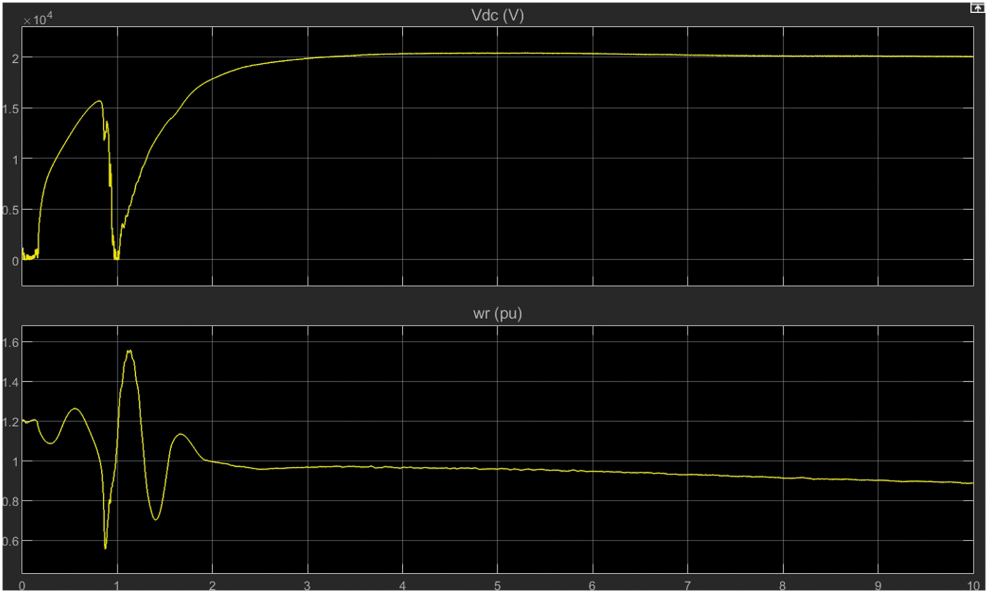
Figure 24: DC voltage
The rotor and grid side convertors are simulated using a machine learning algorithm using the hidden layer network. Two types of activation function namely linear activation function and sigmoid activation function were used and the results are examined.
This paper examined the operation and the different control techniques used in the DFIG system. The DFIG was modeled in MATLAB’s simulation atmosphere and analyzed its performance as a function of wind speed and other operating conditions. Based on the analyses and evaluation of simulation results the machine learning algorithm has been developed for a wind power conversion system to generate maximum power under different conditions of wind speed. In this document, the DFIG wind power conversion system was developed in MATLAB and the machine learning algorithm design for the rotor side and converter side grid. Different kinds of neural networks have been developed such as two layers and four network layers under different activation functions. The ML algorithm was developed and trained in a MATLAB environment and controls the converter at the rotor end and the converter at the grid end. Finally, the simulated outcomes are assessed and demonstrate the effectiveness of the proposed system.
Acknowledgement: We would like to express my deep gratitude to Professor Dr. C. Mythili and Dr. H. Vennila for their guidance and encouragement in planning and developing this research work. We would also like to thank Dr. S. Suresh Kumar for spending his valuable time for providing technical support. Finally, we thank our family for their support and encouragement throughout the research.
Funding Statement: The authors received no specific funding for this study.
Conflicts of Interest: The authors declare that they have no conflicts of interest to report regarding the present study.
1. H. Shao, X. Cai, Z. Li, D. Zhou, S. Sun et al., “Stability enhancement and direct speed control of DFIG inertia emulation control strategy,” Institute of Electrical and Electronics Engineers Access, vol. 7, pp. 120089–120105, 2019. [Google Scholar]
2. X. Zhu, S. Liu and Y. Wang, “Second-order sliding-mode control of DFIG-based wind turbines,” in Proc. 3rd Renewable Power Generation Conf., Naples, Italy, pp. 706–712, 2014. [Google Scholar]
3. A. Djoudi, H. Chekireb, S. Bacha and E. M. Berouk, “Lower gain adaptive sliding mode control of DFIG stator powers,” in Proc. 3rd Renewable Power Generation Conf., Naples, Italy, pp. 409–415, 2014. [Google Scholar]
4. M. Venkateshkumar and R. Raghavan, “Hybrid photovoltaic and wind power system with battery management system using fuzzy logic controller,” International Journal of Applied Power Engineering, vol. 5, no. 2, pp. 72–78, 2016. [Google Scholar]
5. P. Cheng and H. Nian, “Collaborative control of DFIG system during network unbalance using reduced-order generalized integrators,” Institute of Electrical and Electronics Engineers Transactions on Energy Conversion, vol. 30, no. 2, pp. 453–464, 2014. [Google Scholar]
6. T. Hemanand, N. P. Subramaniam and M. Venkateshkumar, “Comparative analysis of intelligent controller based microgrid integration of hybrid PV/wind power system,” Journal of Ambient Intelligence and Humanized Computing, vol. 99, no. 5, pp. 1–20, 2018. [Google Scholar]
7. R. A. J. Amalorpavaraj, P. Kaliannan, S. Padmanaban, U. Subramaniam and V. K. Ramachandaramurthy, “Improved fault ride through capability in DFIG based wind turbines using dynamic voltage restorer with combined feed-forward and feed-back control,” Institute of Electrical and Electronics Engineers Access, vol. 5, pp. 20494–20503, 2017. [Google Scholar]
8. K. Xiahou, Y. Liu, L. Wang, M. S. Li and Q. H. Wu, “Control of DFIG’s rotor-side converter with decoupling of current loops using observer-based fractional-order sliding-mode regulators,” Institute of Electrical and Electronics Engineers Access, vol. 7, pp. 163412–163420, 2019. [Google Scholar]
9. P. Cheng, C. Wu, J. Ma and F. Blaabjerg, “Coordinated derived current control of DFIG’s RSC and GSC without PLL under unbalanced grid voltage conditions,” Institute of Electrical and Electronics Engineers Access, vol. 8, pp. 64760–64769, 2020. [Google Scholar]
10. Y. Song and H. Nian, “Modularized control strategy and performance analysis of DFIG system under unbalanced and harmonic grid voltage,” Institute of Electrical and Electronics Engineers Transactions on Power Electronics, vol. 30, no. 9, pp. 4831–4842, 2014. [Google Scholar]
11. K. Xiahou, Y. Liu, L. Wang, M. S. Li and Q. H. Wu, “Switching fault-tolerant control for DFIG-based wind turbines with rotor and stator current sensor faults,” Institute of Electrical and Electronics Engineers Access, vol. 7, pp. 103390–103403, 2019. [Google Scholar]
12. P. Li, J. Wang, L. Xiong and M. Ma, “Robust nonlinear controller design for damping of sub-synchronous control interaction in DFIG-based wind farms,” Institute of Electrical and Electronics Engineers Access, vol. 7, pp. 16626–16637, 2019. [Google Scholar]
13. B. Xu, D. Chen, M. Venkateshkumar, Y. Xiao, Y. Yue et al., “Modeling a pumped storage hydropower integrated to a hybrid power system with solar-wind power and its stability analysis,” Applied Energy, vol. 248, no. 3, pp. 446–462, 2019. [Google Scholar]
14. S. Tian, Z. Li, H. Li, Y. Hu and M. Lu, “Active control method for torsional vibration of DFIG drive chain under asymmetric power grid fault,” Institute of Electrical and Electronics Engineers Access, vol. 8, pp. 155611–155618, 2020. [Google Scholar]
15. D. Sun, H. Long, K. Zhou, Y. Lv, J. Zheng et al., “Research on SCESS-DFIG DC bus voltage fluctuation suppression strategy for frequency inertia regulation of power grid,” Institute of Electrical and Electronics Engineers Access, vol. 8, pp. 173933–173948, 2020. [Google Scholar]
16. A. M. Eltamaly, M. S. Al-Saud and A. G. Abo-Khalil, “Dynamic control of a DFIG wind power generation system to mitigate unbalanced grid voltage,” Institute of Electrical and Electronics Engineers Access, vol. 8, pp. 39091–39103, 2020. [Google Scholar]
17. A. Djoudi, H. Chekireb, E. Berkouk and S. Bacha, “Real time estimation of DFIG inductances and rotor currents,” in Proc. 3rd Renewable Power Generation Conf., Naples, Italy, pp. 433–438, 2014. [Google Scholar]
18. J. Han, Z. Liu and N. Liang, “Nonlinear adaptive robust control strategy of doubly fed induction generator based on virtual synchronous generator,” Institute of Electrical and Electronics Engineers Access, vol. 8, pp. 159887–159896, 2020. [Google Scholar]
19. X. Tian, Y. Chi, W. Wang, G. Li, H. Tang et al., “Transient characteristics and adaptive fault ride through control strategy of DFIGs considering voltage phase angle jump,” Proc. Journal of Modern Power Systems and Clean Energy, vol. 5, no. 5, pp. 757–766, 2017. [Google Scholar]
 | This work is licensed under a Creative Commons Attribution 4.0 International License, which permits unrestricted use, distribution, and reproduction in any medium, provided the original work is properly cited. |