DOI:10.32604/iasc.2023.025884
| Intelligent Automation & Soft Computing DOI:10.32604/iasc.2023.025884 | |
| Article |
Intelligent MRI Room Design Using Visible Light Communication with Range Augmentation
Department of CSE, Coimbatore Institute of Technology, Coimbatore, 641014, India
*Corresponding Author: R. Priyadharsini. Email: dharsini.r@gmail.com
Received: 08 December 2021; Accepted: 15 February 2022
Abstract: Radio waves and strong magnetic fields are used by Magnetic Resonance Imaging (MRI) scanners to detect tumours, wounds and visualize detailed images of the human body. Wi-Fi and other medical devices placed in the MRI procedure room produces RF noise in MRI Images. The RF noise is the result of electromagnetic emissions produced by Wi-Fi and other medical devices that interfere with the operation of the MRI scanner. Existing techniques for RF noise mitigation involve RF shielding techniques which induce eddy currents that affect the MRI image quality. RF shielding techniques are complex and lead to RF leakage. VLC (Visible light Communication) is an emerging and efficient technology to avoid RF interference near MRI scanners. Range augmentation with power conservation of the LED is a big challenge in existing VLC systems. The major objective of the proposed work is to develop an intelligent-MRI room design without RF interference using visible light communication and enhance the distance between VLC transmitter and VLC receiver. In this paper, it is proposed to implement VLC using On-Off keying modulation and enhance distance using large active area photodiodes with Automatic Gain Control Circuit (AGC) using software and hardware. The performance of the proposed intelligent MRI-VLC system is analyzed by calculating Bit Error Rate at an inclined distance of 50 cm away from line of sight of the LED. The Experimental results showed that the maximum distance achieved was 400 cm at Bit Error Rate (BER) of 1.5 × 10⁻⁵.
Keywords: Visible light communication; intelligent magnetic resonance imaging in VLC; BER
Magnetic Resonance Imaging (MRI) machines use a powerful magnetic field to produce two Dimensional (2D) or three Dimensional (3D) images of the internal body. It is a non-invasive radiology which has the capability to represent morphological alterations in the body. It is used to differentiate a healthy and a diseased tissue of internal organs. It helps in early detection and treatment of disease without any side effects. Positron Emission Tomography (PET) combined with MRI, a hybrid imaging technique is useful for functional, structural, and molecular imaging. Simultaneous acquisition of PET data when PET detectors are integrated into MRI gantry can produce RF interference which can result in noise artifacts in MRI images. The strong magnetic field of MRI rooms malfunctions any electronic equipment inside the room due to RF interference. To prevent electromagnetic radiation from distorting the MRI signal and to prevent the electromagnetic radiation generated by the MRI scanner from causing interference with nearby medical devices, RF shielding is mandatory.
The RF shielding includes enclosure of the entire room such as walls, floor, and ceiling with copper wrapped wood panels. This RF shielding technique is very tedious and complex, since the ceiling should be suspended from the RF shield to provide space for lightning. The door must be sealed by a set of electric contacts or metallic pneumatic tube. Due to repetitive opening and closing, the RF shield around the door is frequently damaged and provides a common source of RF leakage into the room. Moreover, pipes and wires through the walls require penetration panels that contain RF filters and waveguides. The RF shielded MRI room produces RF leaks when a high field strength magnet over 4000 kg is placed inside shielded room [1]. Also after installation of the field strength magnet, environmental factors such as moisture also creates problem in RF shielding that leads to RF leakage.
The Existing systems use Radio Frequency (RF) shielding techniques to avoid RF interference in hospitals. Lepola et al. proposed a method for mitigation of Radiofrequency interference for EEG measurement. The electrodes of the Electroencephalograph (EEG) device were shielded by graphite or silver, which reduced the radiofrequency interference of the electrodes due to power lines. The silver layer shielding achieved a better immunity (p < 0.05) than the graphite shielding (p = 0.029) to the RF interference [2]. Pastore et al. proposed an application of carbon nano powder for concrete in building walls of hospital environment to mitigate the radiofrequency interference with the medical devices [3]. Konpang et al. developed a four port network using diplexers for wireless communication for RF interference rejection [4]. Debaillie et al. developed a dual-polarized antenna and an electrical balance duplexer for RF interference cancellation. But implementation of Duplexer and Diplexers increases the noise figure in the receiver and also simultaneous transmission and reception is not possible using duplexers [5].
Maramraju et al. proposed an aluminum shield and segmented copper shield to minimize the RF interference in MRI compatible Positron Tomography [6]. Eclov et al. implemented a notch filter to reduce RF interference in the PET data for simultaneous acquired PET-MRI [7]. Gebhardt et al. proposed RESCUE-Reduction of MRI-Signal to Noise Ratio (SNR) degradation by using an MR-synchronous low-interference PET Acquisition technique. In this method, the PET data acquisition during the reception of the MR signal was interrupted to minimize the RF interference and the SNR of the MRI data was preserved [8]. Gebhardt et al. also implemented a modified firmware using Field Programmable Gate Array (FPGA) in an MR-compatible PET device. The clock frequencies of the PET device were shifted to reduce the RF interference [9]. Lee et al. implemented optical cables of 20 m long instead of electrical connection between the PET and MRI ground. The optical cables make the PRT detectors float from the MRI ground which can reduce the RF interference in PET compatible MRI [10]. Lim et al. proposed an aluminum-plated conductive fabric shield for PET detectors in hybrid PET/MRI. The Aluminum conductive fabric shield was inserted into the PET detector to reduce the RF interference in hybrid PET/MRI [11]. But the existing RF shielding in MRI, induce eddy currents which affect the MRI image quality. Additionally, the installation of filters, optical cables, and firmware increases the complexity of the MRI and the cost of installation. The proposed Intelligent MRI system is based on VLC (Visible light Communication), one of the emerging and efficient technologies to avoid RF interference near MRI scanners. VLC is very safe, cost effective, and robust for communication against radio frequency interferences [12].
VLC uses Light Emitting Diode (LED) for transmission, where the data is encoded with the intensity of light. Photo detectors such as photodiodes, Light Dependent Resistors (LDRs), and photo-transistors are used. A photodiode is highly recommended in VLC, since it has better fall-rise time compared to photo-transistor and LDR. On the other hand, a photodiode can be replaced by an LED that can act both as transmitter and receiver. White to white LED communication was proposed by Kim and Lee, where a data rate of 200 b/s and a distance of 10 cm were achieved [13]. A red to red LED VLC system was implemented by Varanava and Kantipudi at a frequency of 1 KHz and distance achieved was 7.6 cm [14].
Cheong et al. investigated a VLC system for biomedical signal transmission. Electrocardiography (ECG) signal with patient information was transmitted at a distance of 50 cm and a BER of 10−6 was achieved [15]. Dhatchayeny et al. demonstrated transmission of Electroencephalography signal (EEG) using VLC. RGB LEDs were used to transmit the EEG data in parallel streams of red, green, and blue color at a limited distance of 50 cm. By using this color cluster of LEDs for EEG transmission, the reliability and efficiency of the VLC system were improved [16]. Tan et al. transmitted real-time biomedical signal ECG signal along with patient information using VLC following HL7 protocol at a distance of 50 cm [17]. Priyadharsini and Kunthavai discussed a limited range VLC system of about 60 cm for Photoplethysmograph and Oxygen Saturation (SPO2) transmission [18]. He et al. proposed a real-time audio and video broadcasting system. Audio and video were captured using a Video camera, amplified and both the data were superimposed with the help of a T-bias circuit [19]. The distance achieved using this method was 2 m. The distance achieved by the existing VLC systems was very less which can be enhanced by a cluster of LEDs at the transmitter. This could not be considered as an optimal solution as more energy is wasted by using a cluster of LEDs that decreases the power efficiency of the VLC system. The main objective of the proposed intelligent MRI-VLC is
• To reduce RF interference in MRI scanners using VLC.
• To increase the range of communication even when the transmitter and the receiver are at non-line of sight with each other.
The proposed system can be used by doctors and healthcare experts for MRI image analysis. In the proposed system, the MRI procedure room is linked to the MRI control room as well as to the diagnosis room. The Image acquisition is performed by the MRI technician in the MRI control room. The doctors analyze the received MRI image in the diagnosis room.
2 Intelligent MRI-VLC System Design
MRI machines, in the presence of Wireless Fidelity (Wi-Fi) or any other medical devices, produce Radio frequency interference. Currently, RF shielding techniques are mandatory in MRI procedure rooms to avoid RF interference. Owing to the complexity of RF shielding techniques, the intelligent MRI indoor room design is proposed that uses visible light communication for MRI images, instead of Wi-fi. MRI rooms are already equipped with LED lights through which MRI is transmitted. The geometrical model of the proposed design is shown in Fig. 1. The proposed intelligent MRI-VLC set up has LED as transmitter, fixed to the ceiling and the receiver is attached to the MRI bed that moves inward and outward direction to scan and produce 2D or 3D images of the internal body of the patient. The received images are sent to the diagnosis center for further investigation.
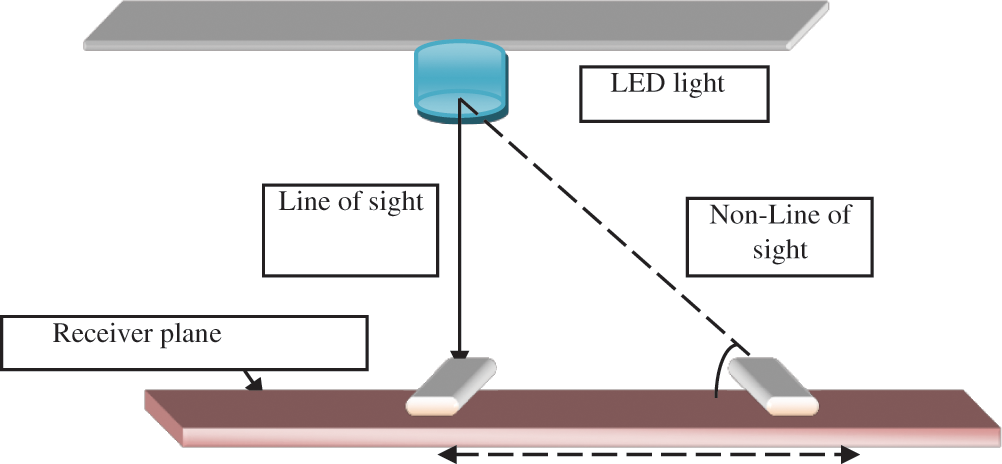
Figure 1: The geometrical model for the proposed design
When the transmitter and the receiver are in the line of sight with each other, the radiation angle of the LED will be wide and directed towards the field of view of the receiver. Consequently, the output voltage will be optimized. The radiation angle of the LED will be directed away from the field of view of the receiver when both the transmitter and the receiver are in non-line of sight with each other as a result of which the received output voltage will be minimized. There is a need to increase output voltage for demodulation in the case of non-line of sight communication. Figs. 2 and 3 show the Intelligent MRI-VLC system with Transmitter in Line Of Sight (LOS) and non-line of sight with the receiver.
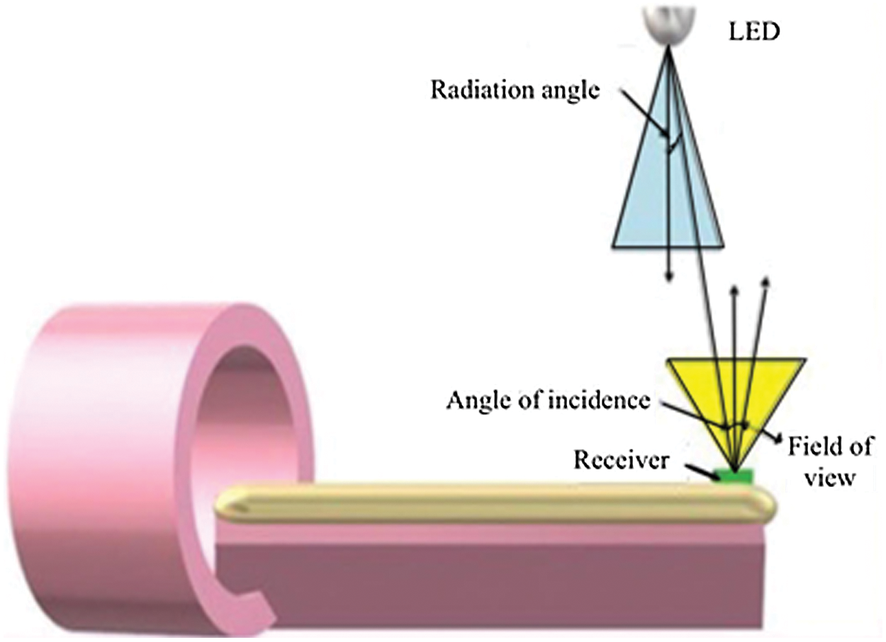
Figure 2: Intelligent MRI-VLC system with transmitter in line of sight (LOS) with receiver
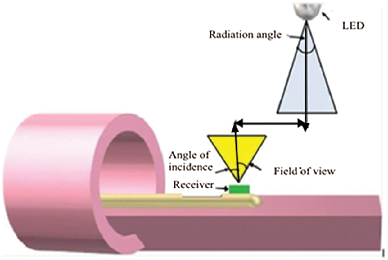
Figure 3: Intelligent MRI-VLC system with transmitter in non-LOS with receiver using AGC
The Transmitter in the MRI procedure room is linked to the Personal Computer (PC) in the control room where the MRI image acquisition is performed by the MRI technician and the receiver placed in the MRI bed is linked to the diagnosis room, where the doctors interpret the results. The MRI bed comes into the line of sight as shown in Fig. 2 and to the non-line of sight as shown in Fig. 3 with the receiver. As the patient lies on the MRI bed, the 2D or the 3D image of the body is viewed by MRI technician in the control room, the PC in the control room is embedded with the LabVIEW code for VLC transmission through the LED. The VLC transmission code is a LabVIEW program for image transmission through a VISA port. The image acquisition is performed using NI-IMAQ in LabVIEW. The acquired MRI image is read and converted into pixel values. The pixel values are extracted into the 2D array and converted into spreadsheet strings using the spreadsheet string function. These spreadsheet strings are to be transmitted through a VISA port. An FDTI-USB to UART driver converts the spreadsheet strings into data signals and sends them to the transmitter circuit.
The transmitter circuit has a 555 timer circuit that generates 100 KHz carrier signals to drive the LED. The modulation is performed by a 555 timer using On-Off Keying (OOK) modulation. ULN203 is used as an LED driver to boost the voltage signals that drive high-power LED. A 3 watt LED is used for communication as well as illumination. The Receiver circuit is attached to the MRI bed. At the stationary position, the receiver is in the line of sight with the transmitter. The field of view of the LED is increased without using high-power LEDs in the MRI room. The receiver circuit consists of a trans-impedance amplifier with a photodiode. The received signal is corrupted by noise from the ambient atmosphere and the receiver electronics. Hence, the signal is applied to a high pass filter to recover the original signal from noise. When the patient MRI-bed is moved inward, the received signal is attenuated as the voltage of the trans-impedance amplifier decreases as the distance increases. Hence there is a need for an automatic gain control circuit to produce constant output voltage, even though incident light is minimal. The output voltage of AGC is fed to the PC in the diagnosis room. The architectural diagram for image transmission and reception is shown in Fig. 4.
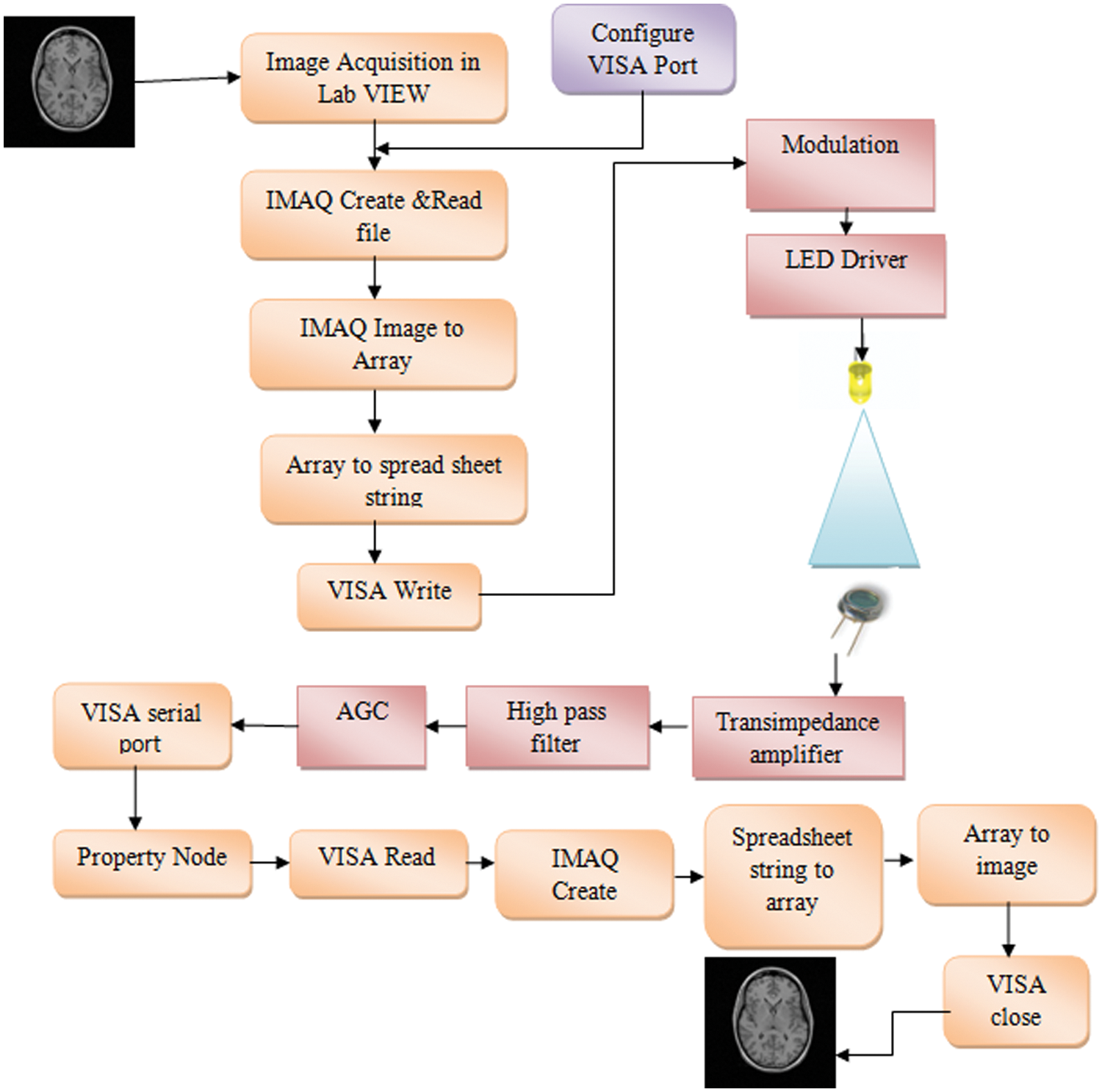
Figure 4: The architectural diagram for image transmission and reception using VLC
In the diagnosis room, the signals are converted from Transistor-Transistor Logic (TTL) logic into RS-232 logic. Demodulation using LabVIEW code is done where the incoming strings are converted into the array and then into an MRI image.
2.1 MRI-VLC Transmitter Design
The proposed VLC transmitter has a 555-timer circuit to generate carrier signals for data modulation as shown in Fig. 5. The hardware circuit of the transmitter circuit is shown in Fig. 6. Fig. 7 shows the oscilloscope output for the 555 timer circuit after OOK modulation.
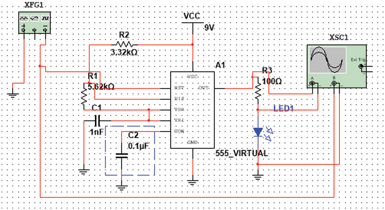
Figure 5: Transmitter 555 timer circuit
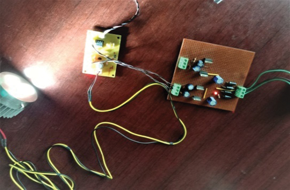
Figure 6: Hardware of the transmitter 555 timer circuit
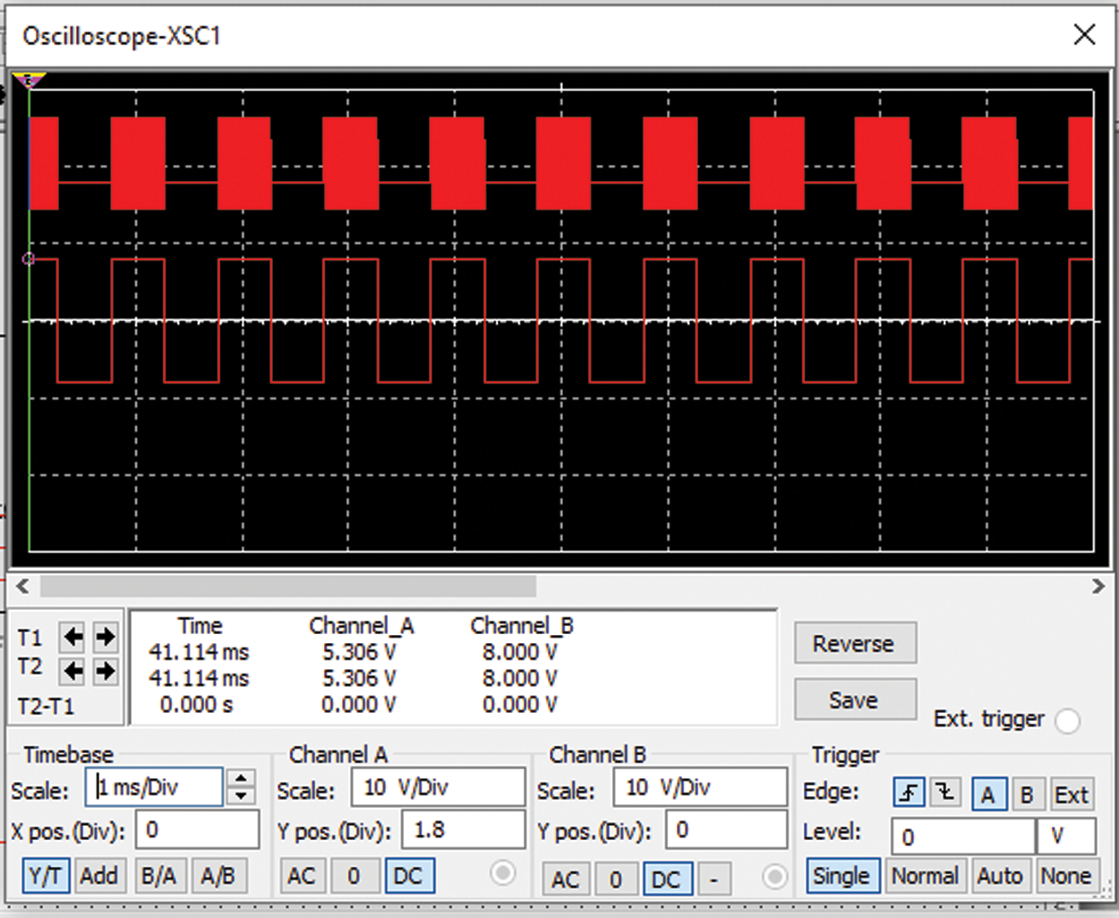
Figure 7: Oscilloscope output of 555 timer circuit after OOK modulation
The proposed analog VLC receiver design has a photodiode, trans-impedance amplifier, filter, Automatic Gain control Circuit (AGC). Along with the hardware design; the circuit was simulated using a simulator tool, TINA TI simulation software that has all features needed for a circuit simulation that helps to run and compile the design and thus saves time and cost for building the circuit in real-time implementation.
The proposed design used two large active photodiodes. One photodiode was OSD-100E from Centronics. It has a responsivity of 60 nA and an active area of 100 mm2. At 12 V, it has a junction capacitance of 520 and 2500 pF at 0 V. This photodiode has peak sensitivity at 630 nm and shunt resistance of 15 M ohm. Another photodiode used is PS-100H from the first sensor. It has an active area of 100 mm2 and a high-speed epitaxial Positive Intrinsic Negative (PIN) photodiode. This photodiode has a non-hermetic ceramic carrier package with a glass window. It has a junction capacitance of 350 pF at 20 V and 1400 pF at 0 V. This photodiode has a shunt resistance of 50 M ohm and responsivity of 0.4 A/Watt at 632 nm.
The trans-impedance amplifier chosen is AD712 from analog devices. This amplifier is desirable for the long-range line of sight and non-line of sight application. The TINA simulation for OSD-100E and PS-100H with trans-impedance amplifier is shown in Figs. 8 and 9. The hardware of the receiver circuit is shown in Fig. 10.
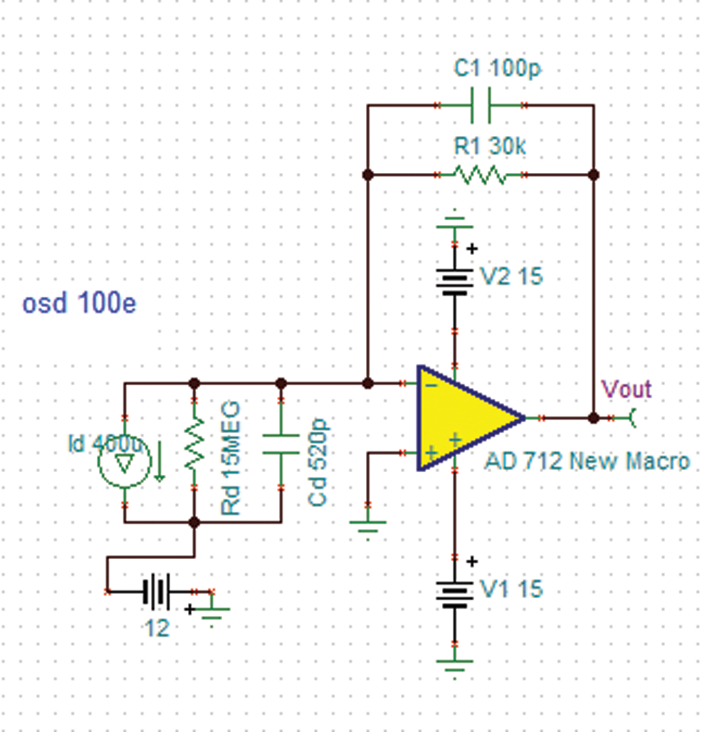
Figure 8: Circuit simulation for OSD-100E
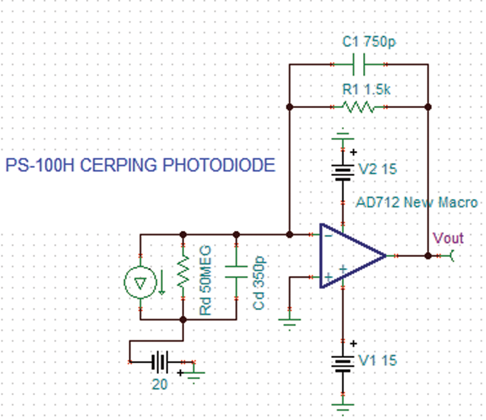
Figure 9: Circuit simulation for PS-100H
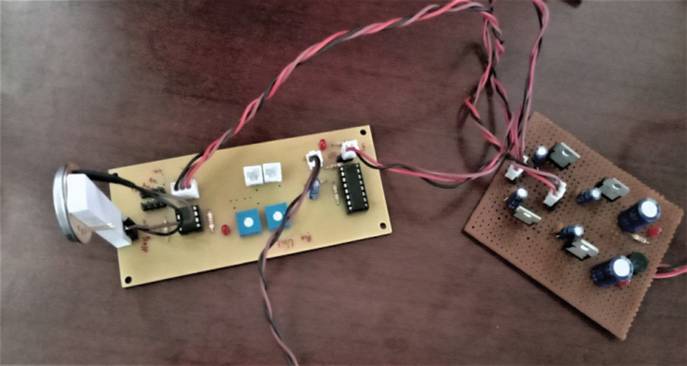
Figure 10: Hardware of the reciever circuit
The design of trans-impedance amplifier uses feedback resistance (Rfb), and feedback capacitance (Cfb) connected in parallel with each other. The value of Rfb [20] is calculated by using Eq. (1)
where, Rfb is the feedback resistance.
Ipeak is the peak current of the photodiode.
Vout is the desired output voltage of the trans-impedance amplifier.
The value of Cfb [20] is calculated using the Eq. (2)
where, Cfb is the feedback capacitance
Cjn is the junction capacitance and Cinput is the input capacitance of the amplifier
F is the desired frequency
The photodiode used in the proposed work is configured in photoconductive mode, where reverse bias is applied to the PN junction of the photodiode, which minimizes the junction capacitance of the photodiode and hence maximizes the width of the depletion region of the photodiode. As a result, the amplifier’s response is fast and stable.
In the proposed intelligent MRI design, an active area high pass filter with a cutoff frequency of 20 kHz using Sallenkey topology was designed to eliminate the interference from the sunlight and ambient incandescent light frequency as shown in Fig. 11. The use of a non-inverting amplifier in Sallenkey topology increases the voltage gain which is apt for long-range communication. The transfer function for the Sallenkey topology [20] is shown in Eq. (3).
where, ω’o = 2πfcC
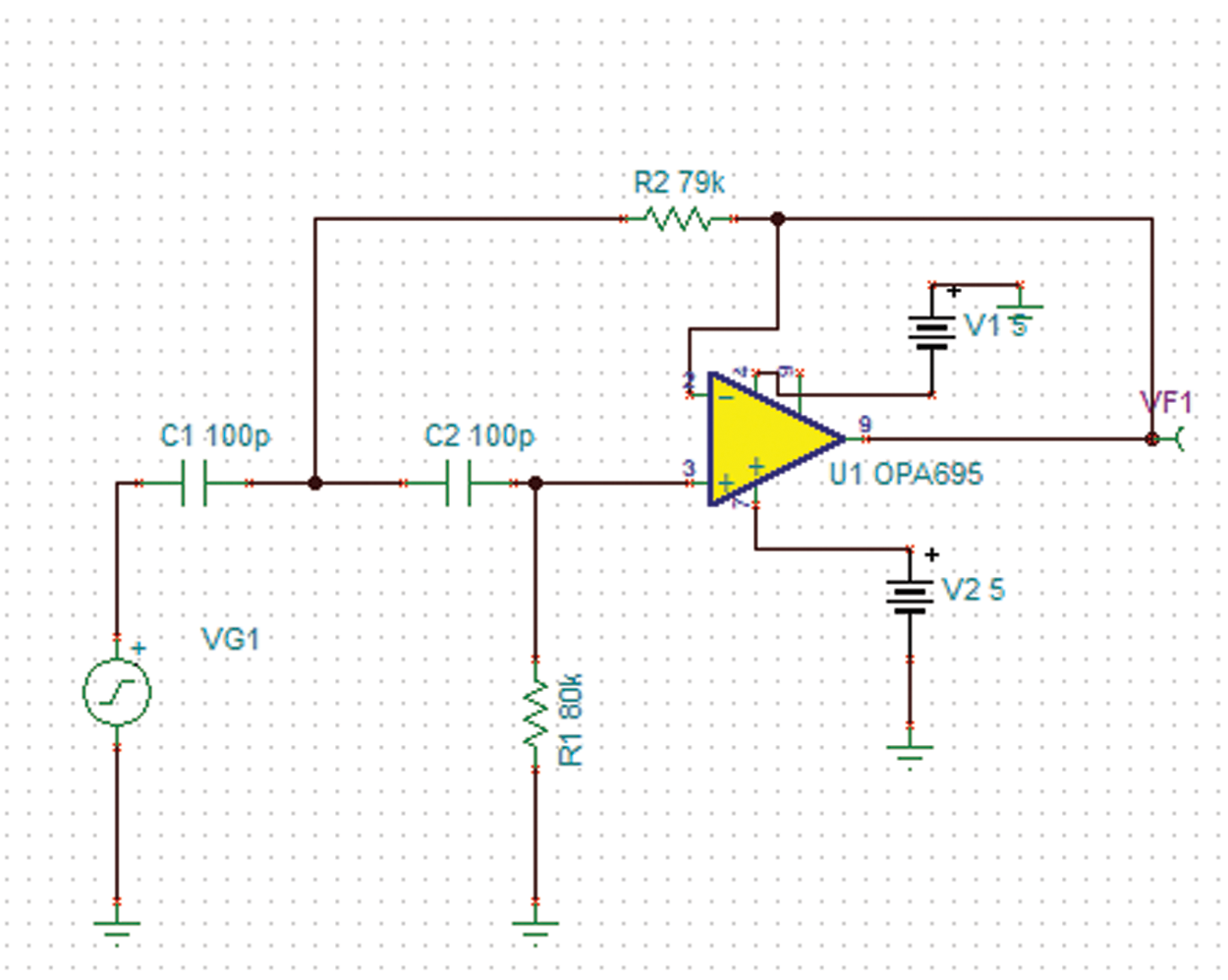
Figure 11: Simulation of high pass filter
In Equation [20] (4), Ra = Rb = R’ and Ca = Cb = C’ = 100 pF is set. The cut off frequency fc = 30 kHz. The value of R is calculated using equation [20] (6) and R = 79 K ohm is obtained.
The main objective of the intelligent-MRI VLC system is to receive MRI images even when both the LED and photodiodes are in non-line of sight and when the MRI scanner is in mobility. Hence, there is a need for an automatic gain control at the output. The design of AGC in an analog front-end receiver circuit makes the output voltage stable without the requirement of the analog comparator with hysteresis in VLC [21]. Yeh et al. proposed automatic gain control in the receiver design where the output received were only up to 1.5 meters [22]. Zhang et al. proposed automatic gain control for dynamic visible light communication where the maximum distance achieved were 3 meters [23]. Fuada et al. designed a VLC system using automatic gain control circuit where the optical distance varied between 30 to 150 cm [24]. An automatic gain control circuit increases the receiver gain when the signal is very weak and reduces the receiver gain when the signal is very strong. The automatic gain control circuit designed for the proposed intelligent MRI system uses LM13700 from Texas instruments. Fig. 12 shows the circuit simulation for the automatic gain control circuit.
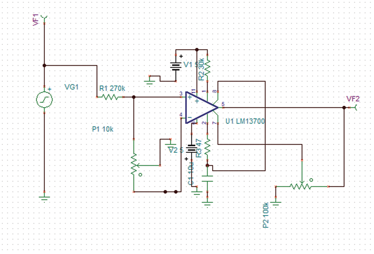
Figure 12: Circuit simulation of automatic gain control circuit
An intelligent-MRI VLC has been implemented for MRI image transmission using VLC and RF interference is eliminated. The proposed intelligent-MRI VLC system is experimentally analyzed using MRI images of different sizes i.e., 100, 115, and 120 KB respectively. These MRI images of the chest are downloaded from a medical database physionet.org. The downloaded MRI images are of T1 weighted type, which has grey matter darker than white matter was used for the proposed work. Images are acquired using Image Acquisition (IMAQ) in LabVIEW and transmitted using visible light in an indoor environment. The downloaded MRI images of various sizes are shown in Figs. 13–15.
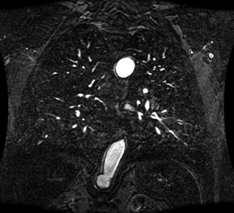
Figure 13: 100 KB MRI image
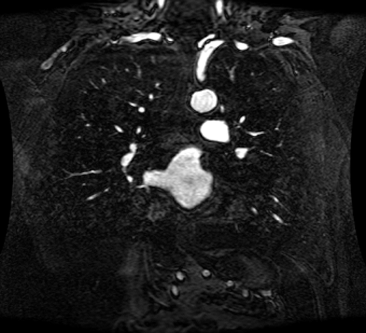
Figure 14: 115 KB MRI image
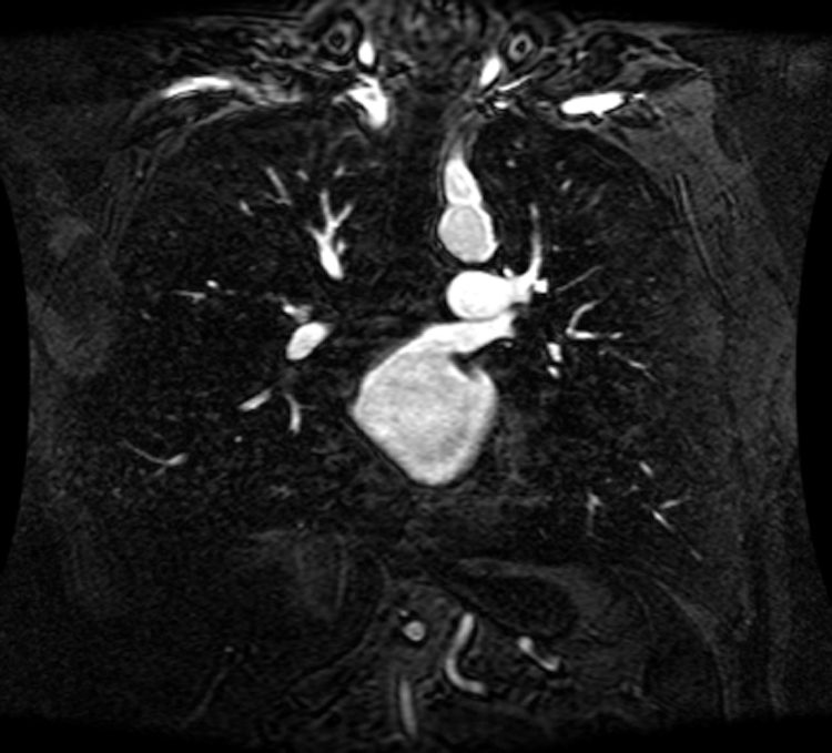
Figure 15: 120 KB MRI image
The field of view of the Receiver is increased by using two large active area photodiodes along with automatic gain control in the receiver. The plot of gain and phase against the frequency of the photodiode is analyzed by ac transfer characteristics. The AC transfer characteristics for OSD-100E and PS-100H photodiodes are shown in Figs. 16 and 17. From Figs. 16 and 17, it is inferred that the photodiode OSD-100E has a better gain of 83 db compared to the PS-100H photodiode that has 59 db at 100 kHz. The gain of the OSD-100E trans-impedance amplifier is better because of its fast response, as the junction capacitance is high for OSD-100E compared to PS-100H which results in a larger collective area and better response compared to the PS-100H photodiode trans-impedance amplifier.
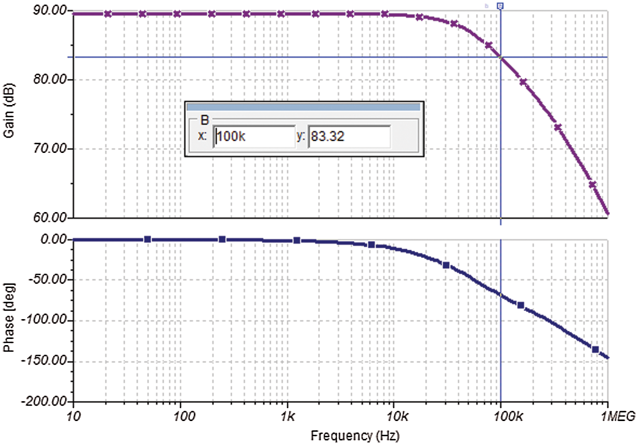
Figure 16: AC transfer characteristics of OSD-100E
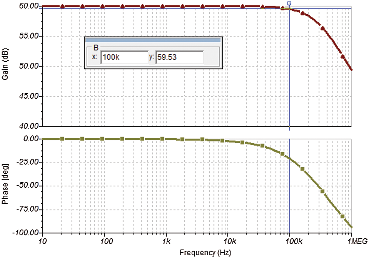
Figure 17: AC transfer characteristics of PS-100H
An active high pass filter with a cut-off frequency of 20 kHz was designed using IC opa695 using Sallenkey topology. This cutoff frequency is chosen to eliminate the ambient light interference. The ac transfer characteristics for the high pass filter are shown in Fig. 18. The automatic gain control circuit was designed using LM13700. The relationship between the input and the output voltage of the AGC circuit is analyzed using the dc transfer characteristics. The dc characteristics of the automatic gain control with input 0.5 to 1 V as well as 0 to 20 V are shown in Figs. 19 and 20, respectively.
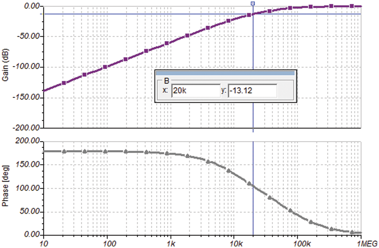
Figure 18: AC transfer characteristics of high pass filter
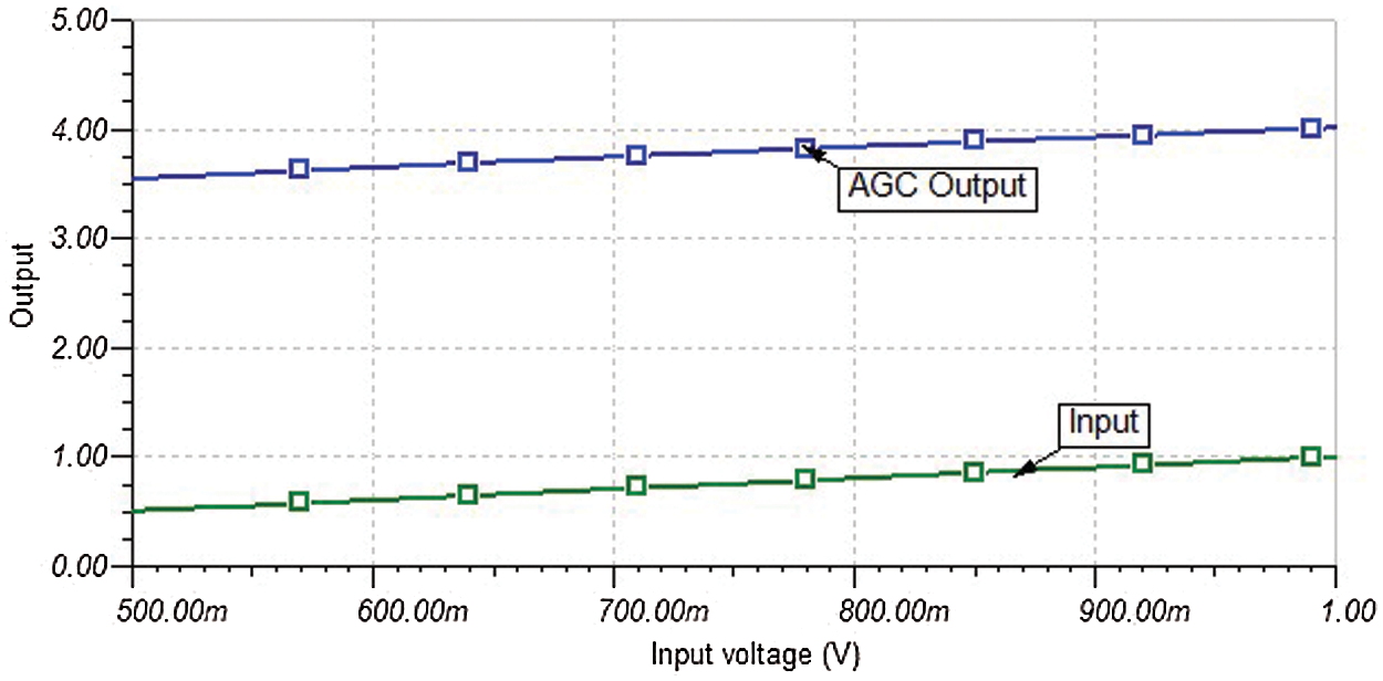
Figure 19: DC transfer characteristics of automatic gain control circuit with input 0.5 to 1 V
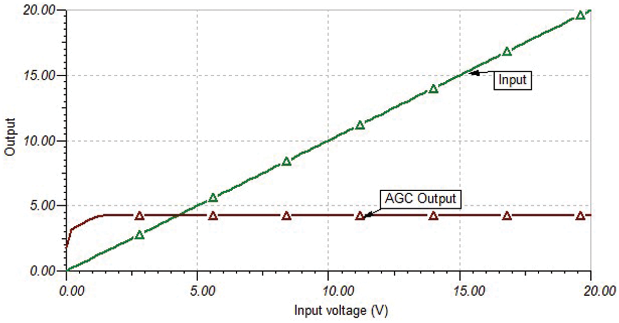
Figure 20: DC transfer characteristics of automatic gain control circuit with input 0 to 20 V
From Figs. 19 and 20, it is observed that even if the input voltage is varied 0.5 to 1 V, and from 0 to 20 V, the output voltage is constant (4 V). Hence, it can be observed that even when the transmitted LED signal is very low, the receiver is able to produce a constant output voltage at a long-range. The proposed intelligent MRI VLC is implemented in both software as well as hardware. MRI images of different sizes are transmitted using LED on the roof of the MRI room and are received at different baud rates in the receiver. The graphs for Baud rate vs. distance for the line of sight and non-line of sight and View angle vs. Baud rate are shown in Figs. 21 and 22, respectively.
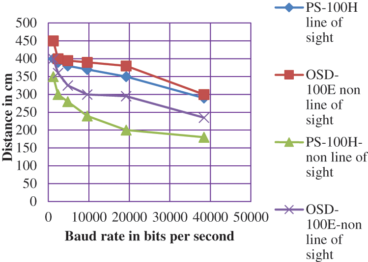
Figure 21: Baud rate in bits per second vs. distance in cm
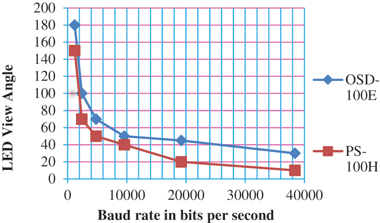
Figure 22: Baud rate in bits per second vs. LED view angle in degrees
The maximum baud rate achieved by both the photodiodes is 38400 bits per second. At 38400 bits per second, the maximum distances achieved are 290 and 300 cm for PS-100H and OSD-100E photodiodes for the line of sight and 235 and 180 cm for the non-line of sight. At 1200 bits per second, a maximum distance of 450 and 400 cm for OSD-100E and PS-100H photodiodes, for the line of sight and 400 and 350 cm for non-line of sight are achieved, respectively. Hence as the speed of the transmission increases, the distance between the transmitter and the receiver decreases. OSD-100E has better speed and response compared to PS-100H photodiode, because of its wider depletion region and less junction capacitance compared to PS-100H photodiode as shown in Fig. 21. The main objective of this proposed work was to increase the field of view of the receiver and to receive the data, even when the LED is kept out of sight from the receiver. The view angle of LED is inversely proportional to the baud rate as shown in Fig. 22.
The receiver received the MRI image even when the LED is oriented 180° away from the line of sight of the receiver at a baud rate of 1200 bits per second as shown in Fig. 22 and the view angle decreased with the baud rate. The performance of the proposed intelligent MRI-VLC system is analyzed by calculating Signal-to-Noise Ratio (SNR), BER. During the course of transmission from LED to the receiver in the MRI plane, the optical power gets attenuated due to noise. Noises such as a shot, thermal, and dark current of the photodiode affect the received optical signal. The Signal to Noise Ratio and BER is calculated using the following Eqs. (7) and (8)
where, Resp is the Responsivity of the photodiode
Pre is the received signal power
σsum_noise is the total noise including shot noise, thermal noise, dark current and noise due to background light.
where,
The BER vs. SNR for PS-100H and OSD-100E is shown in Fig. 23. The standard SNR value in On-Off Keying-Non return to zero (OOK-NRZ) modulation is 13.6 dB, at which the optimum value of BER should be at least 10−6. The theoretical SNR value at 13.6 dB should be a stable error-free communication [25,26]. Hence, the proposed intelligent VLC system is analyzed at 13.6 dB of SNR and error-free at BER of 10−12.
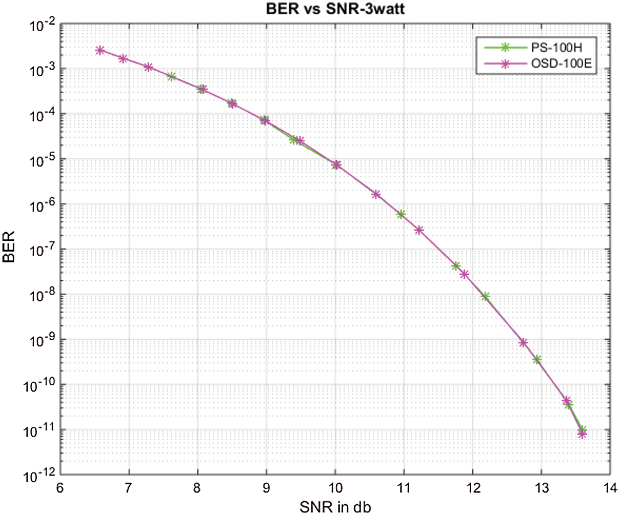
Figure 23: BER vs. SNR
At 13.6 dB, a BER of 8.07 × 10⁻¹² for OSD-100E and a BER of 9.43 × 10⁻¹² for PS-100H photodiodes are achieved. The graphs for BER vs. Distance for OSD-100E and PS-100H are shown in Figs. 24 and 25, respectively. At the distance of 400 cm, BER is 1.5 × 10⁻⁵ for OSD-100E and at 360 cm BER is 2.59 × 10⁻⁵ as shown in the figure. Hence, the BER value is high as the distance increases as shown in Figs. 24 and 25 for OSD-100E and PS-100H photodiodes, respectively.
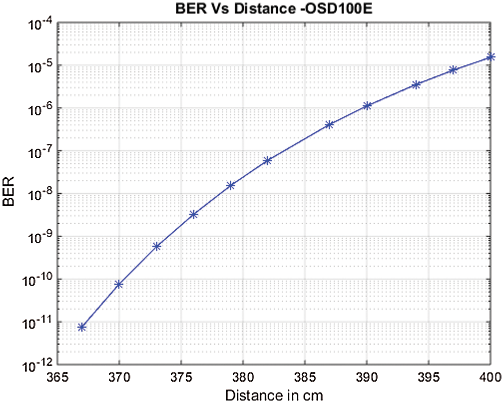
Figure 24: BER vs. distance–OSD-100E
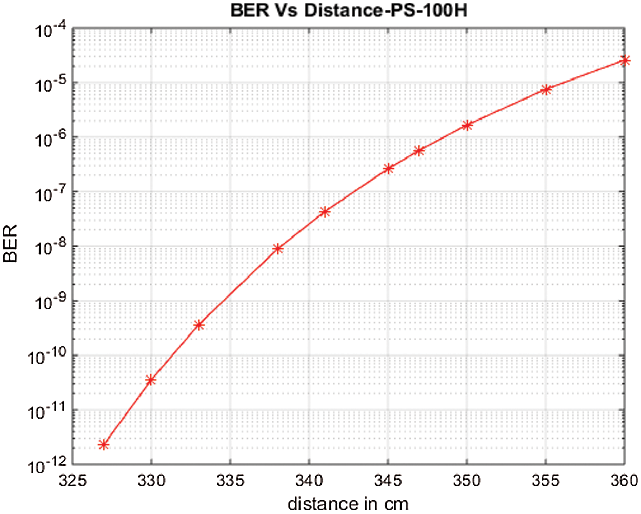
Figure 25: BER vs. distance–PS-100H
From the experimental results, it is clear that MRI images are received even when the receiver was inclined at a distance of 50 cm and an angle of 180° away from the transmitter. Hence, the active area of the receiver is enhanced by using large active area photodiodes like PS-100H and OSD-100E along with the automatic gain control circuit and their performance is analyzed by calculating and plotting Bit error rate against distance.
The RF shielding techniques for MRI were complex and lead to RF leakage. The Existing RF shielding techniques for RF noise mitigation induced eddy currents affecting the MRI image quality. The radio frequency interference at the MRI scan was eliminated using the proposed intelligent MRI design and range augmentation was achieved using the proposed analog VLC receiver with large active area photodiodes and Automatic gain control circuit. The Experimental results show that the MRI images were received even when the receiver was inclined at a distance of 50 cm away from the LED. The implementation cost associated with RF shielding techniques was essentially reduced by using LEDs, which were employed for both communication and lighting. The images were received at a distance up to 400 cm at a bit error rate of 1.5 × 10⁻⁵ for OSD-100E and up to 360 cm, a Bit error rate of 2.5 × 10⁻⁵ for PS-100H respectively. The performance of OSD-100E was better in terms of speed and response compared to the PS-100H photodiode, due to its wider depletion region and less junction capacitance. Therefore, the MRI images can be received even when the receiver plane of the MRI scanner is dynamic. The future work focuses on the real-time transmission of biomedical signals using the proposed receiver hardware and the elimination of noise in real-time biomedical signals using FPGA as well as real time validation of MRI images in hospital. Hence the Radiofrequency interference is eliminated and MRI images are received without any artifacts leading to accurate diagnosis for patients.
Acknowledgement: The author with a deep sense of gratitude would thank the supervisor for her guidance and constant support rendered during this research.
Funding Statement: The authors received no specific funding for this study.
Conflicts of Interest: The authors declare that they have no conflicts of interest to report regarding the present study.
1. M. Gaidosh, “Technique for locating rf leaks in the flooring of electromagnetic shielding enclosures,” in IEEE International Symposium on Electromagnetic Compatibility & Signal/Power Integrity (EMCSI), Reno, NV, USA, pp. 537–542, 2020. [Google Scholar]
2. P. Lepola, S. Myllymaa, J. Töyräs, E. Mervaala, R. Lappalainen et al., “Shielded design of screen-printed eeg electrode set reduces interference pick-up,” IEEE Sensors Journal, vol. 14, no. 8, pp. 2692–2697, 2014. [Google Scholar]
3. R. Pastore, D. Micheli, A. Vricella, R. B. Morles and M. Marchetti, “Advanced concrete materials for EMI reduction in protected environment and IEMI threats suppression,” in Int. Conf. on Environment and Electrical Engineering (EEEIC), Rome, Italy, pp. 2011–2016, 2015. [Google Scholar]
4. J. Konpang, M. Sandhu, N. Somjit and I. Hunter, “Novel RF interference rejection technique using a four-port diplexer,” in European Microwave Conf. (EuMC), London, UK, pp. 524–527, 2016. [Google Scholar]
5. B. Debaillie et al., “RF Self-Interference Reduction Techniques for Compact Full Duplex Radios,” in IEEE 81st Vehicular Technology Conference (VTC Spring), Glasgow, UK, pp. 1–6, 2015. DOI 10.1109/VTCSpring.2015.7146059. [Google Scholar] [CrossRef]
6. S. H. Maramraju, S. D. Smith, S. Rescia, S. Stoll, M. Budassi et al., “Electromagnetic interactions in a shielded PET/MRI system for simultaneous PET/MR imaging in 9.4T: Evaluation and results,” IEEE Transactions on Nuclear Science, vol. 59, no. 5, pp. 1892–1899, 2012. [Google Scholar]
7. N. Eclov, H. Kim, H. T. Chen, C. T. Chen, A. Ronzhin et al., “Notch filtering of RF interference in PET data for simultaneous PET-MR acquisition,” in IEEE Nuclear Science Symp. and Medical Imaging Conf. (NSS/MIC), Seattle, WA, USA, pp. 1–3, 2014. [Google Scholar]
8. P. Gebhardt, J. Wehner, B. Weissler, T. Frach, P. K. Marsden et al., “RESCUE-reduction of MRI SNR degradation by using an mr-synchronous low-interference PET acquisition technique,” in IEEE Transactions on Nuclear Science, vol. 62, no. 3, pp. 634–643, 2015. [Google Scholar]
9. P. Gebhardt, J. Wehner, B. Weissler, F. Kiessling, P. K. Marsden et al., “RF interference reduction for simultaneous digital PET/MR using an FPGA-based, optimized spatial and temporal clocking distribution,” in IEEE Nuclear Science Symp. and Medical Imaging Conf. (2013 NSS/MIC), Seoul, Korea (Southpp. 1–5, 2013. [Google Scholar]
10. B. J. Lee, P. D. Olcott, K. J. Hong, A. M. Grant, C. M. Chang et al., “Studies of electromagnetic interference of PET detector insert for simultaneous PET/MRI,” in IEEE Nuclear Science Symp. and Medical Imaging Conf. (2013 NSS/MIC), Seoul, Korea (Southpp. 1–3, 2013. [Google Scholar]
11. H. K. Lim, Y. Choi, J. H. Jung, J. Jung, C. H. Oh et al., “Evaluation of RF noise shielding effectiveness for the improvement of MR image in hybrid PET/MRI,” in IEEE Nuclear Science Symp. and Medical Imaging Conf. (2013 NSS/MIC), Seoul, Korea (Southpp. 1–3, 2013. [Google Scholar]
12. H. Elgala, R. Meslehand and H. Haas, “Indoor optical wireless communication: Potential and state-of-the-art,” IEEE Communications Magazine, vol. 49, no. 9, pp. 56–62, 2011. [Google Scholar]
13. S. M. Kim and H. J. Lee, “Half-duplex visible light communication using an LED as both a transmitter and a receiver,” International Journal of Communication Systems, vol. 29, no. 12, pp. 1889–1895, 2016. [Google Scholar]
14. D. J. Varanva and M. V. V. Kantipudi, “LED to LED communication using WDM,” International Journal of Computer Applications, vol. 72, no. 19, pp. 36–38, 2013. [Google Scholar]
15. Y. Cheong, X. Ng and W. Chung, “Hazardless biomedical sensing data transmission using VLC,” IEEE Sensors Journal, vol. 13, no. 9, pp. 3347–3348, 2013. [Google Scholar]
16. D. R. Dhatchayeny, A. Sewaiwar, S. V. Tiwari and Y. H. Chung, “Experimental biomedical EEG signaltransmission using VLC,” IEEE Sensors Journal, vol. 15, no. 10, pp. 5386–5387, 2015. [Google Scholar]
17. Y. Y. Tan, S. Jung and W. Chung, “Real time biomedical signal transmission of mixed ECG signal and patient information using visible light communication,” in Annual Int. Conf. of the IEEE Engineering in Medicine and Biology Society (EMBC), Osaka, Japan, pp. 4791–4794, 2013. [Google Scholar]
18. R. Priyadharsini and A. Kunthavai, “A remote monitoring of photoplethysmography signals and spo2 in COVID wards using visible light communication,” Tieraztliche Praxis, vol. 41, pp. 158–167, 2021. [Google Scholar]
19. Y. He, L. Ding, Y. Gong, and Y. Wang, “Real-time audio & video transmission system based on visible light communication,” Optics and Photonics, vol. 03, no. 02, pp. 153–157, 2013. [Google Scholar]
20. Z. Ghassemlooy, W. Popoolaand S. Rajbhandari, “Optical wireless communications: system and channel modelling with Matlab®”, CRC Press, Boca Raton, Florida, pp. 77–83, 2019. [Online]. Available: https://doi.org/10.1201/9781315151724. [Google Scholar]
21. S. Deng, E. Cleary, M. A. McAuliffe and L. Lewis, “Design of an auto-gain control transimpedance amplifier for optical sensing applications,” IEEE Irish Signals and Systems Conf. (ISSC), Londonderry, pp. 1–5, 2016. [Google Scholar]
22. C. H. Yeh, Y. L. Liu, C. W. Chow, “Real-time white-light phosphor-LED visible light communication (VLC) with compact size,” Optic Express, vol. 21, no. 22, pp. 26192–26197, 2013. [Google Scholar]
23. Y. Zhang, X. Jin, W. Jiang, X. Chen and Z. Xu, “Experimental investigation of dynamic visible light communication system with automatic gain control,” Asia Communications and Photonics Conf., Chengdu China, pp. 1–3, 2019. [Google Scholar]
24. S. Fuada, T. Adiono and A. Pradana, “Employing LM13700 as AGC for mobile visible light communication system,” Int. Journal of Electrical and Electronic Engineering & Telecommunications, Singapore, Asia, pp. 88–93, 2020. [Google Scholar]
25. L. A. Azizan, M. S. Ab-Rahman, M. R. Hassan, A. A. A. Bakar and R. Nordin, “Optimization of signal-to-noise ratio for wireless light-emitting diode communication in modern lighting layouts,” Optical Engineering, vol. 53, no. 4, pp. 1–10, 2014. [Google Scholar]
26. R. Paudel, Z. Ghassemlooy, H. Le Minh, S. Rajbhandari and E. Leitgeb, “Lambertian source modelling of free space optical ground-to-train communications,” in Int. Symp. on Communication Systems, Networks & Digital Signal Processing (CSNDSP), Poznan, Poland, pp. 1–5, 2012. [Google Scholar]
 | This work is licensed under a Creative Commons Attribution 4.0 International License, which permits unrestricted use, distribution, and reproduction in any medium, provided the original work is properly cited. |