DOI:10.32604/iasc.2023.026069
| Intelligent Automation & Soft Computing DOI:10.32604/iasc.2023.026069 | |
| Article |
Gaussian PI Controller Network Classifier for Grid-Connected Renewable Energy System
1Department of Electrical Computer and Telecommunications Engineering, Botswana International University of Science and Technology, Botswana
2Department of Electrical and Electronics Engineering, Vel Tech Rangarajan Dr. Sagunthala R&D Institute of Science and Technology, Chennai, Tamil Nadu, India
3Department of Electrical Power Engineering, College of Engineering, Defence University, Ethiopia
4Department Electrical and Electronics Engineering, New Prince Shri Bhavani College of Engineering and Technology, Sembakkam, Tamil Nadu, India
*Corresponding Author: Ravi Samikannu. Email: ravis@biust.ac.bw
Received: 14 December 2021; Accepted: 14 February 2022
Abstract: Multi-port converters are considered as exceeding earlier period decade owing to function in a combination of different energy sources in a single processing unit. Renewable energy sources are playing a significant role in the modern energy system with rapid development. In renewable sources like fuel combustion and solar energy, the generated voltages change due to their environmental changes. To develop energy resources, electric power generation involved huge awareness. The power and output voltages are plays important role in our work but it not considered in the existing system. For considering the power and voltage, Gaussian PI Controller-Maxpooling Deep Convolutional Neural Network Classifier (GPIC-MDCNNC) Model is introduced for the grid-connected renewable energy system. The input information is collected from two input sources. After that, input layer transfer information to hidden layer 1 fuzzy PI is employed for controlling voltage in GPIC-MDCNNC Model. Hidden layer 1 is transferred to hidden layer 2. Gaussian activation is employed for determining the output voltage with help of the controller. At last, the output layer offers the last value in GPIC-MDCNNC Model. The designed method was confirmed using one and multiple sources by stable and unpredictable input voltages. GPIC-MDCNNC Model increases the performance of grid-connected renewable energy systems by enhanced voltage value compared with state-of-the-art works. The control technique using GPIC-MDCNNC Model increases the dynamics of hybrid energy systems connected to the grid.
Keywords: Multi-port converters; renewable sources; fuzzy PI controller; gaussian activation function; fuel cell
Renewable Energy (RE) is measured as significant with different energy. A grid-connected system is used considerably by higher diversity. RE is used in many applications namely Solar electric, or Photo Voltaic (PV), systems, power generation, wind turbines. With the improvement of modern and innovative inverter configurations, competence, size, load, consistency performance is enhanced. Dynamic modelling by Multiple Input Multiple Output (MIMO) controller was introduced in [1] with two parallel Direct Current (DC)-Direct Current (DC) boost converters. MIMO controller was used for the highest power of PV/FC. After the progress of a unique model for the whole system, a decoupling network was developed for system input-output linearization because of the inherent connection of the control outputs with all of the system inputs. But voltage was not regulated at the required level. A wind turbine generator with a battery was employed in [2] for supplying a grid-connected load of a multi-input RE system. The phase-shift control method was introduced to manage power among sources, loads as well as grid. The system utilizes a multi-winding transformer to integrate the renewable energies and transfer them to the load or battery. However, computational complexity was not reduced by the designed technique. A multi-input single-output converter was introduced in [3] to restrict the duty cycle for minimizing energy consumption. The designed method was enhanced with a reduction in the part count. The designed converter contains various features, namely a simple gate driving pattern, improves energy source utilization and output, it extended to N-inputs. But the computational complexity was not minimized by a multi-input single-output converter.
A robust blended Iterative Linear Quadratic Gaussian (ILQG) controller was designed in [4] for a secondary network of PV-based hybrid sources of Alternating Current (AC)-DC microgrid. The proposed blended integral linear-quadratic-Gaussian controller gives a large control bandwidth to minimize the oscillation but also verifies the improved tracking performance over the number of loads in SN premises. However, the computational cost was not reduced by the ILQG controller. The control strategy was employed in [5] for a PV system. Designed strategy increased performance of power quality by the three-phase grid-connected system through optimizing PI controller. The Particle Swarm Optimization (PSO) technique was introduced to tune the PI controller parameters by reducing the error of the voltage regulator and current controller schemes in the inverter system. Though the power quality performance was reduced, the voltage attained was not required level by control strategy. Particle Swarm Optimization tuned Proportional Integral Derivative (PSOPID) controller was introduced in [6] for load occurrence organizes. The designed method suppressed frequency deviation due to weight and establishing power fluctuations. An interconnected thermal and hydro and wind power system was measured with conventional controllers like PI and PID, from that the PID controller gives the optimal solution. Two-area hydrothermal system problems with I, PI, and PSO optimized controller. However, the rated grid current was not attained by the PSOPID controller. A multi-input rectifier topology was carried out in [7] for the Permanent Magnet Synchronous Generator (PMSG) scheme. In order to buck converter topology, MPPT based PV control was employed. A multi-input rectifier phase was used to eliminate the current harmonics. The Perturb and Observe (P&O) MPPT employed for MPPT demonstrates the compassion among generated power with and without a tracker. But the computational complexity was not minimized by multi-input rectifier topology.
A three-phase multi-level multi-input power converter topology was introduced in [8] for grid-associated utilizations. In the open-end winding configuration, it included a three-phase transformer accomplished on the primary side. Primary winding was supplied on one side through a three-phase N-level neutral point clamped inverter and, another by an auxiliary two-level inverter. However, the attained voltage was not at the required level. Belt Driven Started Generator (BDSG)-inverter was introduced in [9] for battery energy storage systems. Interleaved procedure and ripple of inductor gets minimized. The designed BDSG inverter has individual power control capability for every battery module whereas fulfills the functions of battery charging and discharging through pulsating current. However, the computational complexity level was not reduced by BDSG-inverter. A grid-tied PV scheme was introduced in [10] with Current Fed (CF)-Dual Active Bridge (DAB) DC–DC converter by cascaded multilevel inverter. The designed method used the minute dc-link capacitor. A novel variable step-size MPPT algorithm was introduced for ensuring high MPPT efficiency, and also fast maximum power extraction. But, the obtained current was not improved by a grid-tied PV system. The problems recognized from the above literature like lesser current, lesser voltage, higher computational complexity, lesser rated grid current, higher computational cost, higher time consumption, and so on. To address the above-said problems, an efficient model called Gaussian PI Controller-based Maxpooling Deep Convolutional Neural Network Classifier (GPIC-MDCNNC) method is developed.
The contribution of the paper is given by.
• The main aim of the GPIC-MDCNNC Model is to attain rated current and voltage for grid-connected RE systems. GPIC-MDCNNC Model, input information is collected from two input sources, namely ‘photovoltaic’ and ‘fuel cell’.
• The input layer transfers information to hidden layer 1 fuzzy PI regulates the speed for attaining the required voltage in GPIC-MDCNNC Model.
• The hidden layer 1 result is transferred to hidden layer 2. Gaussian activation function determines the output voltage with help of the controller.
• At last, the output layer offers the last value in GPIC-MDCNNC Model.
The paper is summarized by: Section 2 explains related works. Section 3 describes the proposed GPIC-DCNLC Model methodology by architecture diagram. Section 4 presents experimental settings as well as a discussion. Section 5 describes the conclusion of this paper.
The coordinated control strategy is designed in [11] for microgrid by energy resources and AC/DC loads. MPPVC technique presented higher voltages for transmitting power among dc and ac sub-grids. A system-level Energy Management Scheme (EMS) was employed to guarantee stable operation in variable power generation and consumption conditions. However, time for control strategy is not reduced with a coordinated control strategy. Model Predictive Control (MPC) scheme was designed in [12] to exactly track sustainable energy resources. It was employed for achieving enhanced power. Incremental Conductance algorithm was an employed base framework with MPC for designing MPPT controller. For power flow control, an MPC controller with discrete-time Kalman filter was used for changing voltage and current references based on input/output power variations from sources and loads. However, the computational cost was not minimized by the MPC scheme.
A real-time Hybrid Control System (HCS) was designed in [13] for grid-connected Hybrid AC/DC Microgrid (HMG). The supervisory control-based optimization was employed to reduce the operating cost with maximum RE usage. Power references for Renewable Energy Resources (RES) were scheduled which utilized as input strength measurement, archived facts and stored climate forecast statistics early measured about modern status. Though the operating cost was minimized, the voltage was not attained at the required level by HCS. A robust feedback linearizing control plan was designed in [14] depending on sliding mode through unbalanced voltages. In normal grid conditions, a control system was employed for maximum power transfer from the photovoltaic source to the grid with maximum power point tracking operation of the DC–DC converter. But the required level was not attained by robust feedback linearizing control plan.
Robust model predictive control method was designed in [15] for photovoltaic to join distribution power system. Designed scheme regulated stable DC-link voltage as well as attained highest power transfer through power factor. Through grid abnormality, the control system was reorganized for maintaining a constant dc-link voltage and protecting the active power and inserting a reactive power to support the grid operation. However, the rated current was not required level by robust model predictive control scheme. An improved current source grid-connected photovoltaic inverter was introduced in [16] where the chopper circuit connected with the DC link. A new control strategy was used to recognize Low Voltage Ride Through (LVRT) control. A novel control approach was designed to recognize LVRT under balanced and unbalanced grid voltage conditions. But the computational cost was not minimized by a grid-connected photovoltaic inverter.
A switched Z-source converter was employed in [17] at the PV side to guarantee continuous current operation through the mode of the grid-connected inverter. Pulse Width Modulation (PWM) rectifier linked with wind turbine transformed AC power into DC. Battery energy management was carried out with an Artificial Neural Network (ANN) for improving the stable power flow and lifespan of the storage system. However, the voltage level was not reduced by switched Z-source converter. FCS-MPC was developed in [18] to control three-phase grid-connected strings depending on the Power Quality (PQ) control scheme. Finite Control Set-Model Predictive Control (FCS-MPC) was employed for attaining high-performance decoupled control of active and reactive powers injected into the grid from Distributed Energy Resources (DER). But the current attained was not at the FCS-MPC.
STATic synchronous COMpensator (STATCOM) was used in [19] for power compensation to improve FRT ability and performance of grid-connected PV/power systems. Fault Ride Through (FRT) control strategy was based on the injection of reactive power from the hybrid system for improving FRT capability during grid faults. But voltage attained was not at the required level by STATCOM. A new hybrid centralized, and distributed control was introduced in [20] for AC/DC micro gridsin for the hybrid renewable energy system. Interlinking Converter (IC) joined the microgrid systems. DC–chopper was utilized to reduce the DC-link over-voltages during grid voltage dips. However, the complexity level was not reduced by hybrid centralized and distributed control
In the present situation, there is a large power demand because of the increasing consumer load with the need for RE sources. The power supply is the main problem for hybrid systems. To maintain the efficiency of the hybrid system, power converters play a vital role in providing the regulated output voltage. Electric power is produced via fossil fuels. With the fast electricity and raise of energy disaster, it was essential for changing fossil fuels by RE. Between renewable resources, solar energy and wind power fascinate large interest because of simple attainment. In the power filter, Grid-connected voltage was employed by online uninterruptable power supplies and RE systems. Grid-connected PV is the electricity-producing solar PV power linked to the effectiveness of the grid. It is parallel to an electric utility grid. It is developed in capacities from hundred watts to tens of megawatts.
3.1 Closed-Loop Control of Grid-Connected Renewable Energy System
In power filter, Grid-connected voltage is employed, online uninterruptable power supply, and RE systems. Fuel Cells (FC), and wind turbines are employed to address the increasing electrical energy demand consistent with the significance of greenhouse gas reduction, RE sources like PV systems. The PV energy application has gained large attention because of the widespread global existence of solar energy. With new developments in solar energy technology, the cost of PV systems is reduced. DC–DC and DC–AC converters are essential for MPPT of renewable source and PV output conversion into AC power correspondingly. From controller design, a grid-connected system is a demanding task because of the cascade connection of multiple converters. Grid-connected inverters were employed for increasing the current quality and active power filtering in the distribution system.
3.2 Multi-Input Multi-Output Converters
Multi-Port Converters (MPCs) play an essential part to enhance MIMO utilization. MPC assumes a crucial job in interfacing and incorporating these vitality sources to supply the heaps. Every subclass is classified into three types, namely Multiple Input Single Output (MISO), Single Input Multiple Output (SIMO) and MIMO. The majority of specialists design the MISO converter to join different vitality sources at different voltage levels. MPCs provide financial procedures as well as enhance the performance of a system by multiple single converters in MIMO. MICs attained better performance with a combination of voltage sources used as EVs and Grid utilization. Multi-Output DC–DC converters received large awareness due to the minimum cost and compact size.
3.3 Converter Topology and Modelling
The circuit topology comprised two separate DC–DC boost converters for the highest power of input sources. Choppers provided the DC link of the grid-connected inverter. MIMO model of a system is used for the controller design. The Control system is the DC–DC boost converters and DC–AC inverter. System controls are power from PV/FC sources as well as AC power in the power grid. The designed system was a three-input three-output circuit. To decouple the controlling loops through considering controller design complexities because of the inherent connection between control outputs and system inputs, the deep convolutional neural network is used. Consistent with bipolar PWM of the inverter, it is clear that inverter output voltage is ‘ux3’. The input current is equal to the ‘ux4’, ‘x3’ and ‘x3’ are amplitude modulation index, inverter DC-link voltage, and grid current correspondingly. The converter has two input sources ‘v1’ PV and ‘v2’ FC. Duty cycles of the switches ‘S1’ and ‘S2’ (‘d1’ and ‘d2’) are the control inputs of DC–DC boost converters. ‘u’ denotes the control input of DC–AC grid-connected inverter in a hybrid energy system. ‘T’ symbolizes the switching period of DC–DC boost converters. ‘xg1’ and ‘xg2’ are the gate signals of the ‘S1’ and ‘S2’ respectively.
3.4 Gaussian PI Controller Based Maxpooling Deep Convolutional Neural Network Classifier (GPIC-MDCNNC) Model for Grid-Connected Renewable Energy System
In GPIC-MDCNNC Model, Deep Learning is a subfield of machine learning inspired by the structure of artificial neural networks. Deep learning comprised multiple layers of neural networks to perform the data processing and computation task. Deep learning in Gaussian PI Controller Deep Convolutional Neural Learned Controller (GPIC-DCNLC) Model depends on the working of the human brain. The deep neural learning classifier structure is illustrated in Fig. 1.
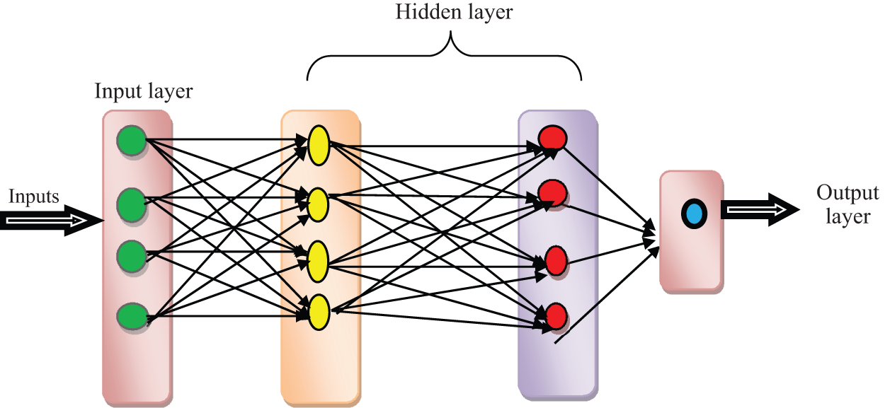
Figure 1: Structure of deep convolutional neural network classifier
Fig. 1 describes the deep neural network classifier structure with various layers. Input data (maximum output voltage obtained from MPPT controller) is sent to hidden layer 1. PI controller was employed in hidden layer 1 to control the input renewable source. After that, the information is sent to hidden layer 2. The Gaussian function was employed in GPIC-MDCNNC Model to reduce the error value and the output results are multiplied by the convolution. Every neuron was associated with each neuron as well as a network is vulnerable to overfitting data. Each neuron accepts input data via each element of the preceding layer. In a neural network, every neuron obtains output value via a particular function. Finally, results are attained in the output layer.
Let us consider, the input source (i.e., a maximum output voltage from PV and FC) was measured as input as well as transferred to the input layer. GPIC-MDCNNC Model determines input value with help of weight vector and bias. It is represented by,
From (1), I(t) represents the input layer for gathering voltage source information at time instant ‘t’, ‘Vs’ denotes the voltage source, ‘wi’ symbolizes the weight of input. ‘Bias’ value is considered as one. Next, inputs are transmitted into hidden layer 1. Fuzzy Proportional Integral (PI) Controller is employed to achieve voltage operation by improved results. In GPIC-MDCNNC Model, Fuzzy Logic is the soft computing technique that accommodates the uncertainty. Fuzzy PI Controller handled the output voltage regulation. Fuzzy control regulates PI control parameters using the fuzzy rule. Depending on the state of the system, adaptive PI is not a linear regulator depending on the principle. The PI is given as,
From (2), ‘PI(t)’ denotes the output of the controller. ‘Kp’ represent the scale parameters. ‘Ti’ indicates the integrator parameter. A fuzzy system is shown as a collection of fuzzy IF-THEN rules. In GPIC-MDCNNC Model every fuzzy rule was denoted with a nonlinear system. System method is attained with the fuzzy blending of the local scheme. It is formulated as,
From (3), ‘f(.)’ denote the nonlinear smooth function. ‘x(t) ∈ Rn×1’ symbolizes the state vector. ‘u(t) ∈ Rn×1’ illustrate the control input. ‘v(t) ∈ Rn×1’ denotes the external disturbance input. TS fuzzy model is formulated as,
From (4) and (5), ‘Ai’, ‘Bi’, ‘Ci’ and ‘Ei’ is the constant by proper dimensions of every fuzzy rule. ‘hi(z(t))’ symbolizes the ith normalized membership function to satisfy the equality. It is given by,
Fuzzy controllers are carried out with specifications under parameter variations and load disturbances. The controller parameters vary accordingly to maintain the desired performance in GPIC-MDCNNC Model. The system used inner loop current control and outer speed control. The outer speed control uses the Takagi-Sugeno-Kang Fuzzy PI controller and their parameters change with the operating conditions while loading.
Fig. 2 describes the Takagi-Sugeno-Kang Fuzzy PI controller design in GPIC-DCNLC Model. The output of the fuzzy PI controller is given by,
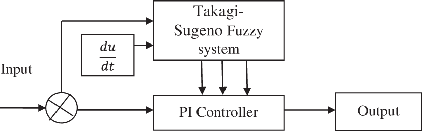
Figure 2: Takagi-Sugeno-Kang fuzzy PI controller
From (7), the fuzzy controller output is attained. ‘
From (8) and (9), ‘h2’ denotes hidden layer 2, ‘
From (10), ‘O(t)’ denotes the output layer. ‘
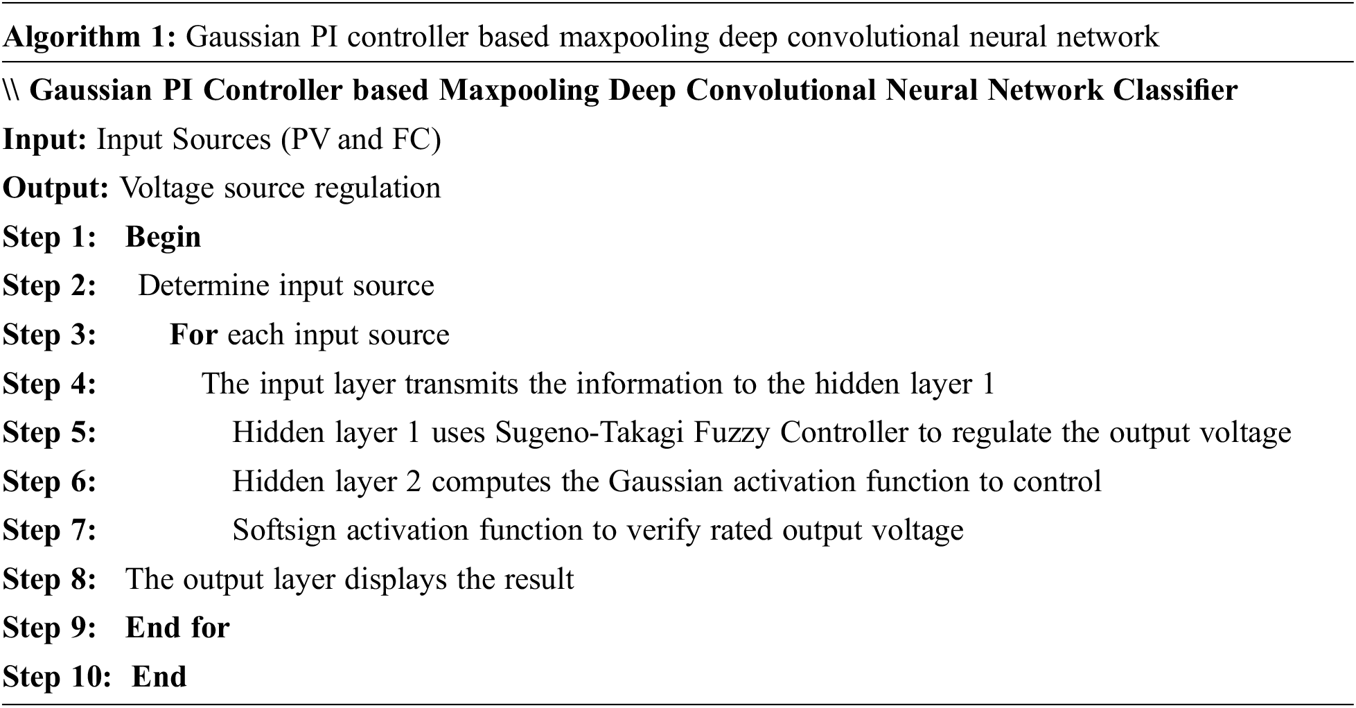
Algorithm 1 explains the algorithmic procedure of PI Controller-based Maxpooling Deep Convolutional Neural Network Classifier for an energy source. Input layer transferred the data to hidden layer 1 fuzzy PI controller is employed for regulating voltage in GPIC-MDCNNC Model. Hidden layer 1 was sent to hidden layer 2. Gaussian activation function was employed for determining output voltage with help of the controller. At last, the output layer demonstrates the last value in GPIC-MDCNNC Model.
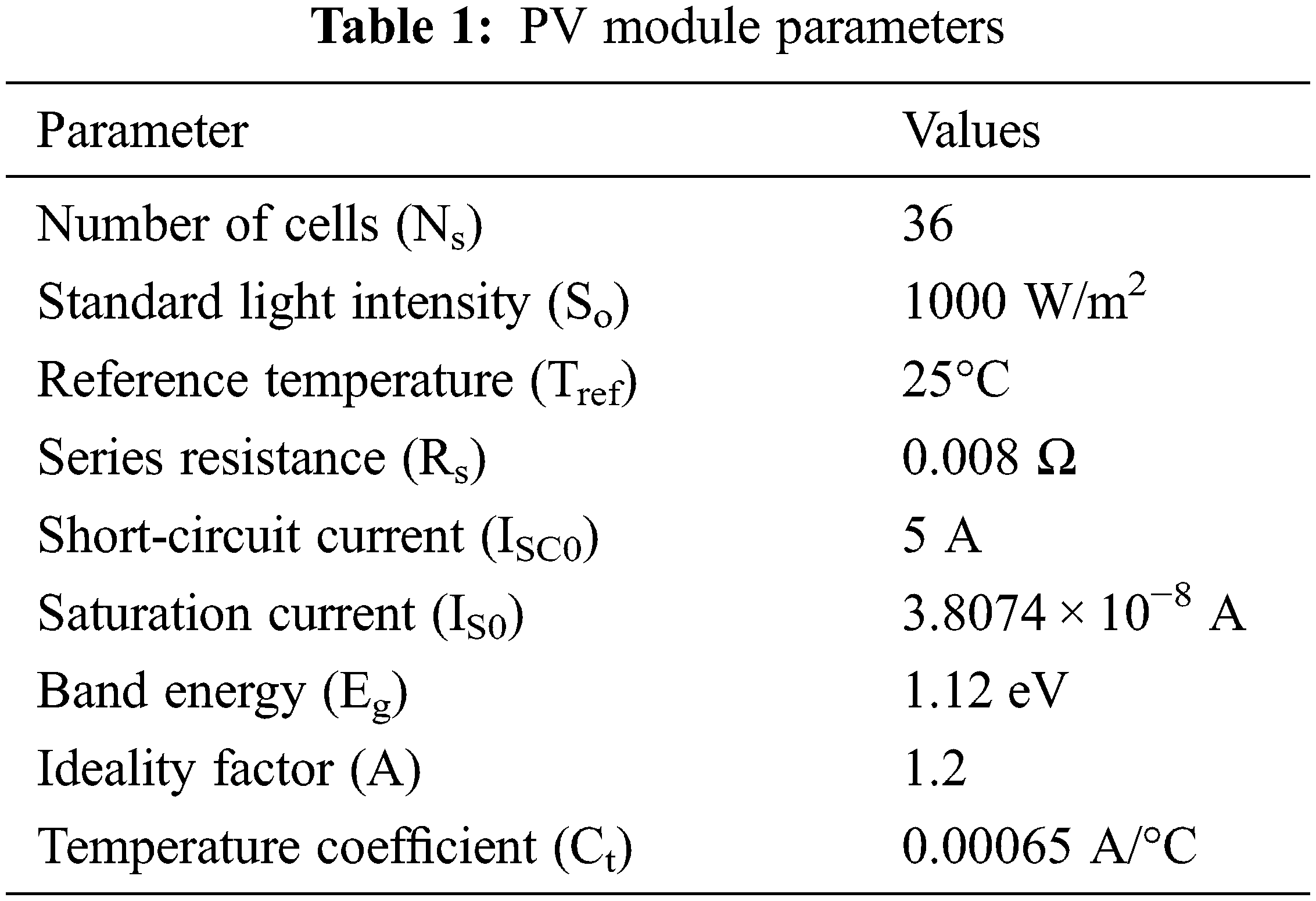
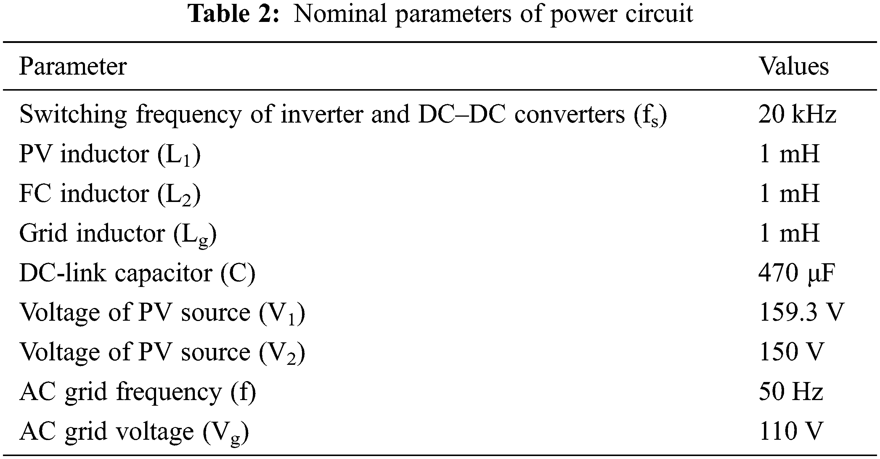
The experimental evaluation of the GPIC-MDCNNC method is implemented with MATLAB Simulink by 3.4 GHz Intel Core i3 processor, To enhance the performance of hybrid grid-connected RE system, 4 GB RAM, and Windows 7 platform was employed. The efficiency of the GPIC-MDCNNC Model is determined along with two different responses, namely steady-state response and transient response for metrics PV panel, Fuel cell stack, DC-link capacitor voltage, and grid current. The main parameters of the PV module and power circuit of values are given below in the Tabs. 1 and 2.
The simulation response of the proposed GPIC-MDCNNC Model for the grid-connected PV/FC hybrid energy system in the nominal condition is illustrated during steady-state operation. It is imagined that Ta = 25°C and S = 1000 W/m2. The reference current of the PV panel is equal to 5 A in MPP. The reference current of the FC stack is equal to 8 A. The designed MIMO controller is used to regulate the DC–DC converter. With reference value, DC link capacitor voltage is regulated. All active power obtained by the renewable source is injected into the grid. Figs. 3–6 describes the steady-state response of PV source output current, FC stack output current, DC-link capacitor as well as grid voltage respectively. AC current is injected in phase with the voltage into the power grid. The grid reference current generated is consistent with DC-link voltage error. The transient response of the proposed MIMO controller is demonstrated during the system start-up process. The reference values of input sources are varied from zero to nominal values. The grid reference current is determined in the outer loop of AC-side MIMO controller by considering the step change of the DC-link capacitor from 0–300 V. The MIMO controller is reliable and fast during the start-up process. The transient response of the proposed GPIC-MDCNNC Model during simultaneous step changes of PV and FC reference currents is illustrated in Figs. 7 and 8. The step response of the proposed GPIC-MDCNNC Model to DC-link reference is illustrated. It is considered that at t = 1.5 s, DC link is stepped as 200 to 400 V. Controller tracked the variations of reference value with the fast dynamic response and zero steady-state error.
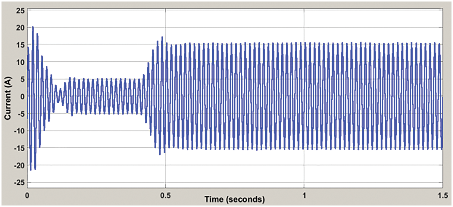
Figure 3: Steady-state response of pv source output current
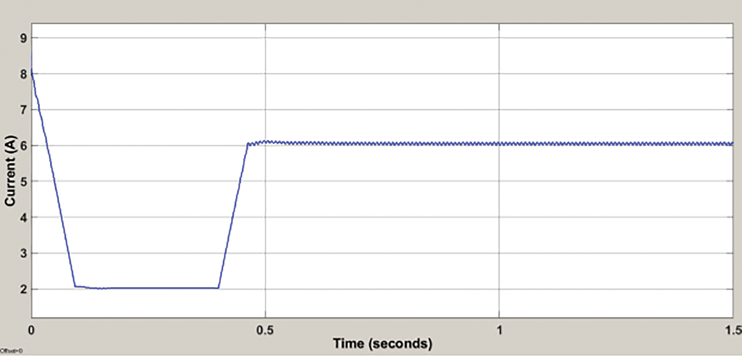
Figure 4: Steady-state response of FC stack output current
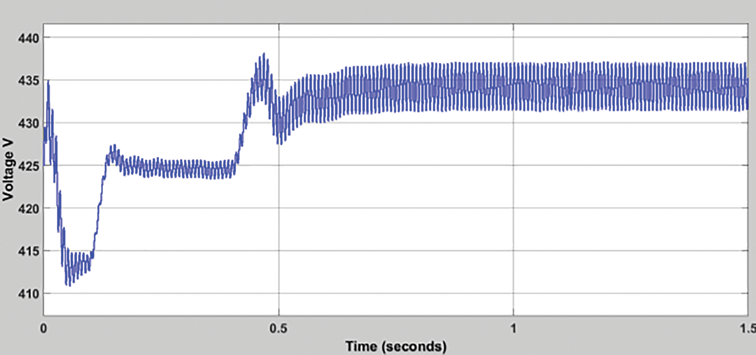
Figure 5: Steady-state response of dc-link capacitor voltage
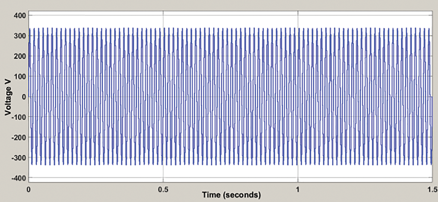
Figure 6: Steady-state response of grid voltage
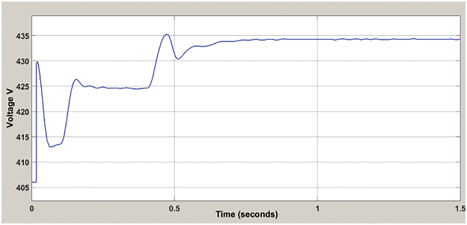
Figure 7: Transient response of dc-link capacitor voltage
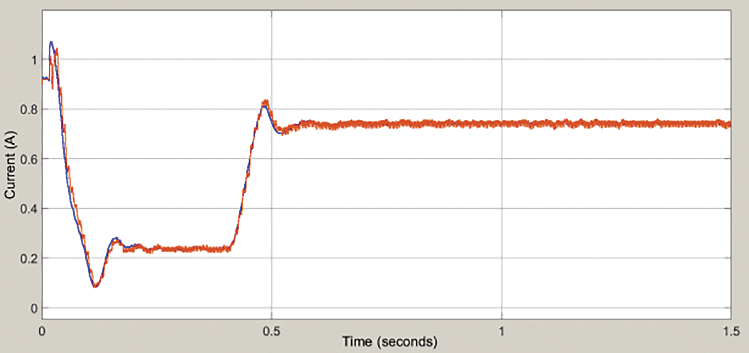
Figure 8: Transient response of grid current
In Fig. 3, at time 0 to 0.4 s the steady State output current is nonstable, and obtained peak oversuit is 20 A. From 0.5 to 1.5 s, the steady-state output current is stable, and obtained peak oversuit is 15 A.
In Fig. 4, at time 0 to 0.4 s, the Steady-State Response of FC stack Output Current is nonstable and current variation is 8 A. From 0.5 to 1.5 s, the Steady-State Response of FC stack Output Current is stable and current variation is 6 A.
In Fig. 5, at time 0 to 0.5 s, the Steady-State Response of DC-Link Capacitor Voltage is stable, and obtained voltage is 437 V. From 0.5 to 1.5 s, the Steady-State Response of DC-Link Capacitor Voltage is nonstable and obtained voltage is 435 V.
In Fig. 6, at time 0 to 1.5 s, the Steady-State Response of Grid voltage is stable and range obtained as 300 V.
In Fig. 7, at time 0 to 0.5 s, the DC-link Capacitor Voltage is stable and obtained voltages as 435 V. From 0.5 to 1 s, the DC-link Capacitor Voltage is nonstable and obtained voltages as 432 V.
In Fig. 8, the Response of Grid Current is nonstable at the range of 0 to 0.5 s, and Grid Current is stable at the range of 0.6 to 1.5 s.
Deep Learning is employed in the proposed GPIC-MDCNNC model for attaining higher output voltage and current. Input layer transfer information to hidden layer 1 through fuzzy PI and then information is transferred to hidden layer 2. It regulates the speed for attaining the required voltage in GPIC-MDCNNC Model. By using the Gaussian activation function output voltage is determined and achieves the required grid current. Finally GPIC-MDCNNC model achieves higher output voltage.
A new model termed GPIC-MDCNNC is introduced to attain higher output voltage for grid-connected RE systems. In GPIC-MDCNNC Model, the input layer transferred data information to hidden layer 1. The fuzzy PI controller regulates the output voltage of the GPIC-MDCNNC Model in hidden layer 1. Hidden layer 1 is transferred to hidden layer 2. Gaussian activation function determines the output voltage with help of the controller and attains the required grid current. Output layer demonstrates the last resultant value in GPIC-MDCNNC Model. The proposed controller succeeded to manage energy between microgrids under different scenarios. The proposed GPIC-MDCNNC Model is capable of MPPT for RE sources and injection of generated power. GPIC-MDCNNC method is evaluated with help of simulations in the MATLAB/Simulink toolbox. Based on the simulation results, the GPIC-MDCNNC Model is completely fast and stable at diverse operation points with zero steady-state error. The proposed GPIC-MDCNNC Model increases the output voltage and output current with minimum time. But, computational complexity was not reduced and Voltage was not regulated at the required level. In future work, Artificial intelligence and soft computing technique are used to attain higher output voltage for grid-connected RE systems with minimum computational complexity.
Funding Statement: The authors received no specific funding for this study.
Conflicts of Interest: The authors declare that they have no conflicts of interest to report regarding the present study.
1. M. Salimi, F. Radmand and M. Hosseini Firouz, “Dynamic modeling and closed-loop control of hybrid grid-connected renewable energy system with multi-input multi-output controller,” Journal of Modern Power Systems and Clean Energy, vol. 9, no. 1, pp. 94–103, 2021. [Google Scholar]
2. M. Jafari and Z. Malekjamshidi, “A hybrid renewable energy system integrating photovoltaic panels, wind turbine, and battery energies for supplying a grid-connected residential load,” SN Applied Sciences, vol. 2, no. 1852, pp. 1–15, 2020. [Google Scholar]
3. M. Dhananjaya, R. Pilla and T. Sekhar Gorripotu, “Integrated multi-input DC–DC converter with reduced switches,” International Transactions on Electrical Energy Systems, vol. 31, no. 8, pp. 1–15, 2021. [Google Scholar]
4. D. Datta, S. Rahman Fahim, S. K. Sarker, S. M. Muyeen, M. R. Islam Sheikh et al., “A robust control method for damping and tracking of secondary network voltage of a PV based hybrid AC/DC microgrid,” Frontiers Energy Research, vol. 7, pp. 1–15, 2020. [Google Scholar]
5. M. F. Roslan, A. Q. Al-Shetwi, M. A. Hannan, P. J. Ker and A. W. M. Zuhdi, “Particle swarm optimization algorithm-based PI inverter controller for a grid-connected PV system,” PLOS ONE, vol. 15, no. 12, pp. 1–31, 2020. [Google Scholar]
6. K. Seetharamayya, “Modelling of load frequency control for a hybrid power system using PID controller,” International Journal of Engineering Research & Technology, vol. 8, no. 16, pp. 1–15, 2020. [Google Scholar]
7. S. A. Mohamed, “Multi-input rectifier stage for a system of hybrid PV/wind driven PMSG,” SN Applied Sciences, vol. 1, no. 1578, pp. 1–13, 2019. [Google Scholar]
8. S. Foti, A. Testa, S. De Caro, L. D. Tornello, G. Scelba et al., “Multi-level multi-input converter for hybrid renewable energy generators,” Energies, vol. 14, no. 1764, pp. 1–19, 2021. [Google Scholar]
9. K. Yuan Lo, Y. M. Chen and Y. R. Chang, “Bidirectional single-stage grid-connected inverter for a battery energy storage system,” IEEE Transactions on Industrial Electronics, vol. 64, no. 6, pp. 4581–4590, 2017. [Google Scholar]
10. Y. Shi, R. Li, Y. Xue and H. Li, “High-frequency-link-based grid-tied PV system with small dc-link capacitor and low-frequency ripple-free maximum power point tracking,” IEEE Transactions on Power Electronics, vol. 31, no. 1, pp. 328–339, 2016. [Google Scholar]
11. J. Hu, Y. Shan, Y. Xu and J. M. Guerrero, “A coordinated control of hybrid AC/DC micro-grids with PV-wind-battery under variable generation and load conditions,” International Journal of Electrical Power and Energy Systems, vol. 104, pp. 583–592, 2019. [Google Scholar]
12. A. Srivastava and R. S. Bajpai, “Model predictive control of renewable energy sources in DC microgrid for power flow control,” International Journal on Energy Conversion, vol. 9, no. 4, pp. 1–15, 2021. [Google Scholar]
13. N. Qachchachi, H. Mahmoudi and A. ElHasnaoui, “Optimization of hybrid AC/DC microgrid in grid-connected mode,” International Journal of Engineering and Advanced Technology, vol. 9, no. 4, pp. 209–214, 2020. [Google Scholar]
14. A. Merabet, L. Labib, A. M. Y. M. Ghias, C. Ghenai and T. Salameh, “Robust feedback linearizing control with sliding mode compensation for a grid-connected photovoltaic inverter system under unbalanced grid voltages,” IEEE Journal of Photovoltaics, vol. 7, no. 3, pp. 828–838, 2017. [Google Scholar]
15. A. Merabet, L. Labib and A. M. Y. M. Ghias, “Robust model predictive control for photovoltaic inverter system with grid fault ride-through capability,” IEEE Transactions on Smart Grid, vol. 9, no. 6, pp. 5699–5709, 2018. [Google Scholar]
16. Y. Geng, K. Yang, Z. Lai, P. Zheng, H. Liu et al., “A novel low voltage ride through control method for current source grid-connected photovoltaic inverters,” IEEE Access, vol. 7, pp. 51735–51748, 2019. [Google Scholar]
17. B. K. Santhoshi, K. Mohanasundaram and L. Ashok Kumar, “ANN-based dynamic control and energy management of inverter and battery in a grid-tied hybrid renewable power system fed through switched Z-source converter,” Electrical Engineering, vol. 103, pp. 2285–2301, 2021. [Google Scholar]
18. M. Azab, “High performance decoupled active and reactive power control for three-phase grid-tied inverters using model predictive control,” Protection and Control of Modern Power Systems, vol. 6, no. 25, pp. 1–15, 2021. [Google Scholar]
19. I. Hamdan, A. M. A. Ibrahim and O. Noureldeen, “Modified STATCOM control strategy for fault ride-through capability enhancement of grid-connected PV/wind hybrid power system during voltage sag,” SN Applied Sciences, vol. 2, no. 364, pp. 1–20, 2020. [Google Scholar]
20. N. H. Saad, A. A. El-Sattar and A. E. A. M. Mansour, “A novel control strategy for grid connected hybrid renewable energy systems using improved particle swarm optimization,” Ain Shams Engineering Journal, vol. 9, no. 4, pp. 2195–2214, 2018. [Google Scholar]
 | This work is licensed under a Creative Commons Attribution 4.0 International License, which permits unrestricted use, distribution, and reproduction in any medium, provided the original work is properly cited. |