DOI:10.32604/iasc.2023.026361
| Intelligent Automation & Soft Computing DOI:10.32604/iasc.2023.026361 | |
| Article |
A Custom Manipulator for Dental Implantation Through Model-Based Design
1Department of Biomedical Engineering, SRM Institute of Science and Technology, Chennai, 603202, India
2Department of Electronics and Instrumentation Engineering, SRM Institute of Science and Technology, Chennai, 603202, India
3Department of Mechatronics Engineering, SRM Institute of Science and Technology, Chennai, 603202, India
*Corresponding Author: Anitha Govindhan. Email: anithag@srmist.edu.in
Received: 23 December 2021; Accepted: 28 February 2022
Abstract: This paper presents a Model-Based Design (MBD) approach for the design and control of a customized manipulator intended for drilling and positioning of dental implants accurately with minimal human intervention. While performing an intra-oral surgery for a prolonged duration within a limited oral cavity, the tremor of dentist's hand is inevitable. As a result, wielding the drilling tool and inserting the dental implants safely in accurate position and orientation is highly challenging even for experienced dentists. Therefore, we introduce a customized manipulator that is designed ergonomically by taking in to account the dental chair specifications and anthropomorphic data such that it can be readily mounted onto the existing dental chair. The manipulator can be used to drill holes for dental inserts and position them with improved accuracy and safety. Furthermore, a thorough multi-body motion analysis of the manipulator was carried out by creating a virtual prototype of the manipulator and simulating its controlled movements in various scenarios. The overall design was prepared and validated in simulation using Solid works, MATLAB and Simulink through Model Based Design (MBD) approach. The motion simulation results indicate that the manipulator could be built as a prototype readily.
Keywords: Model based design; multi-body motion simulation; custom manipulator; orthodontic implants; mathematical approach
Based on various studies conducted worldwide, a huge population is affected with dental diseases. A survey by [1,2] reported nearly 2.4 billion people were affected with dental caries, tooth decay, loss of tooth, injuries in jaw and periodontal disease; the count reaches around 621 million people including the children. These dental diseases cause various problems in day-to-day activities like sleeping and eating; and further it affects the quality of life, as reported in [3,4]. Besides, [5,6] identified that the dental diseases are commonly associated with various chronic conditions/diseases such as cardiovascular diseases, diabetes, obesity, transient ischemic attacks and so forth. Fortunately, the dental implantation is one of the proven techniques to overcome the aforementioned problems and it provides a predictable, effective, and reliable means for tooth replacements. Essentially, dental implantation is a set of procedures to substitute the missing tooth with an artificial tooth wherein the jawbone/mandible is the base upon which all dental procedures are carried out [7]. Hence, dental implantation helps to regain the daily routine of edentulous patients. This includes importantly mastication, deglutition, facial aesthetics and etc. The feel of regained aesthetics enhances the mental and physical well-being of an individual as substantiated in [8,9]. Owing to these reasons, about three million people were subjected to dental implants worldwide and the number is expected to increase year after year. Nevertheless, most people from underdeveloped countries like India have difficulty affording these expensive procedures. This solution needs to be effective and reasonably economical. This work is a step towards creating an implantation system like that. Generally, the existing dental implantation techniques may be broadly categorised as hand drilling method, surgical template guidance method, and vision-guided robotic method. The manual approach has several shortcomings like inaccuracy, safety, and etc. Better accuracy and safety are typically sought when choosing the implantation method, but it is also quite expensive and complex. We propose a dental implantation system centred on a customised manipulator. It is suitable for either surgical template guidance or vision-guided methods. In this paper, we specifically customise a dental manipulator so that it can be fitted onto existing dental chairs.
The primary objective of this work is to develop a custom manipulator that is user-friendly and efficient for performing orthodontic implantation surgery. Furthermore, dental implantation system is typically a mechatronic system and hence we would adopt the model-based design as an integral approach for the design of manipulator. Indeed, we eventually aim to build a high-fidelity digital twin for the entire system. This, we believe, would be an essential feature that might enable the dentist to efficiently perform preoperative planning and validation of surgery on the digital twin before it can be done on patients using the actual system.
1.2 Key Contributions and Salient Features
The key idea behind this work is providing a cost-effective manipulator design that will be an add on for the existing dental chair. It must be flexible and intuitive. However, it should be ensured that the accuracy and safety are not compromised. Thus, the mechatronic approach is adopted to achieve this trade off by optimizing these design metrics through several design iterations and simulations. The major contributions of this work are given below:
• A customized dental robot with a ready-to-mount feature on dental chair by taking in to account the dental chair specifications and anthropomorphic data.
• Step-by-step procedures for the design and analysis of the robot through multi-body motion simulations using Solid works and MATLAB/Simulink.
• An exhaustive simulation of the manipulator in different scenarios.
Dental implantation procedures and issues are briefly outlined in this section. We begin by describing a number of dental implantation methods and their issues. A small incision is made on the gum to expose the jawbone. To avoid temperature elevation and burning of tissue, sequential drilling is then employed. Subsequently, screwing in a crown is done next, followed by placement of a false tooth over on it. Dentists are trained with various surgical models, such as acrylic, plaster of Paris, and 3D surgical models. In the whole implantation procedure, various problems are identified. First, locating the implant site and application of force and torque required to do drilling is major concern [10]. Second, holding a dental hand piece for time taking procedures, application of desired payload and torque and locating the proper position of implant site could cause muscle fatigue and tremor in the hand [11]. Third, manual handling of dental drill creates phobia.
Furthermore, the manual dental implantation procedures require lot of skills to achieve preciseness, and above all, they are highly time-consuming [9,12]. Due to these reasons, most often the manual methods failed miserably in spite of dentist's experience. Evidently, improper positioning would result in technical complication, damaging of vital structure of jaw and affect aesthetic and appearance. The aesthetic failure may even lead to psychological problems [13]. In a nutshell, drilling a hole precisely for implantation is a bottle-neck task. The increasing number of patients with dental problems, lack of healthcare professionals to meet this supply and demand and requirement of preciseness in these procedures opened new technological development in dental health industries. The advancement in the field of robotics fused with dental healthcare requirements brought in various robots for dental applications in the recent past. The solutions started with training and assisting the surgeon during the surgery. Then the training robots were used to simulate human response, so that surgeon could learn and get trained [14–16]. The Food and Drug Administration (FDA) agency approved its first robotic surgery in the field of dental in 2017. The researchers from China invented another robot which can perform implantation surgery autonomously [9,17–19]. Most recently, a method exploiting the human-robot collaboration was proposed by [20], where the authors claim that the accuracy and safety of implantation were improved through such collaboration.
Model based design is a proven approach for developing complex engineering systems like the one presented in this paper. For instance, consider various processes involved in a typical dental implantation system as shown in Fig. 1, which involves several conflicting design requirements. This means that the system design will undergo a number of iterations with various design changes and refinements before the final optimal design is arrived at. Although the major focus of this work is on only the design and control of a manipulator, the overall process involved in the implantation method is illustrated here for the sake of completeness, which enables one to get the system level picture, inter-dependency among various subsystems and above all the reason behind using the MBD approach for the design. The entire dental implantation process can be described in five steps from a system perspective as follows: The first step is image acquisition wherein the details of mandibular bone along with teeth are scanned and stored as images using Cone-Beam Computed Tomography systems (CBCT).
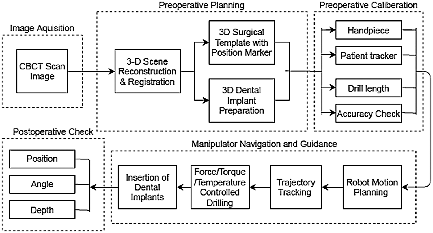
Figure 1: Dental implantation processes
The second step is preoperative planning wherein the images acquired from the previous step are used to reconstruct a 3D model of the mandibular bone and teeth. Further, image registration is done to get the 3D model in oral coordinate system. From this, most crucial details are obtained to decide the location, size, angle and depth details for drilling hole and select or fabricate appropriate dental implant. In addition, surgical template with marker is also designed and fabricated in this step if required. Third step is preoperative calibration in which the dental hand piece, drill bit and patient tracker are calibrated. In the fourth step, the trajectories are generated and executed by the manipulator according to the locations where holes are drilled as planned in the second step. Subsequently, the implants are immersed in the designated holes. Finally, in the fifth step, postoperative check is done to assess if any deviation from the preoperative planning. It can be understood that these processes are highly interwoven and any issue in one process will affect the overall system performance adversely. Furthermore, inaccuracies in image acquisition and uncertainties in sensors and models would result in accuracy and safety issues in the final implantation process. Therefore, the mechatronic approach allows us tight integration of these subsystems using concurrent development that is inherently achieved by the help of MBD. In this work, we use Solid works software to design the mechanics of the manipulator, and the MATLAB/Simulink software to perform multi-body motion simulations similar to the work in [21]. In addition, we derive kinematic and dynamic models of the manipulator to aid the simulation and validate some results analytically.
The proposed robot has five links and four revolute joints (4R configuration) as shown in Fig. 2a. The links and joints are formed in such a way that the manipulator gives joint-1 the freedom of rotating a full 360° as shown in Fig. 2b, joint-2 with 60° and joint-3 with 120° as shown in Fig. 2c, joint-4 with 360° as well as shown in Fig. 2d. The simplified Computer Aided Design (CAD) is shown in Fig. 2e, the assigned frames of all links are shown in Fig. 2f and simplified CAD model (left) and the frames assignment (right) are shown in Fig. 2g.
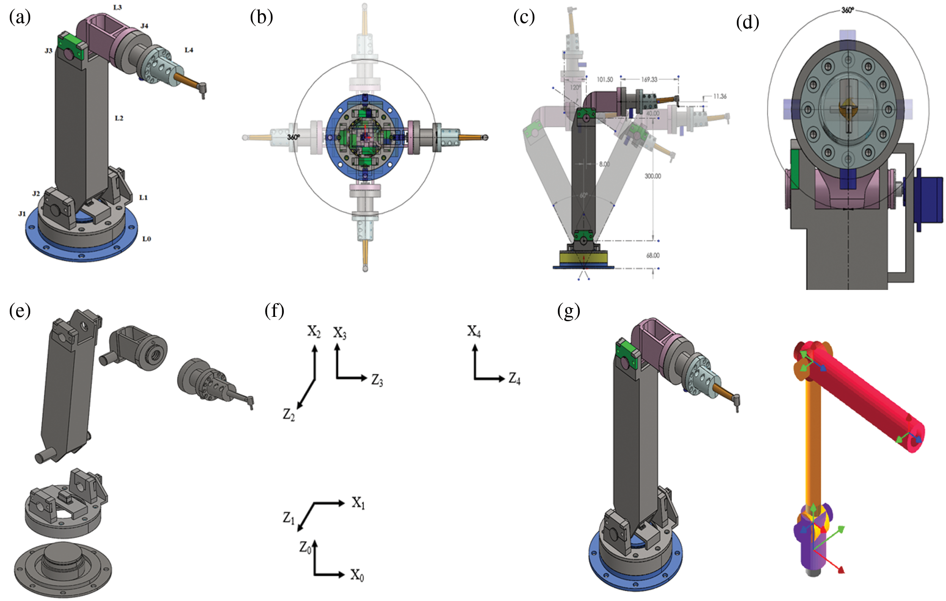
Figure 2: The customized dental manipulator:(a) CAD model of the customized dental manipulator with five links designated as L0, L1, L2, L3 and L4, and four revolute joints designated as J1, J2, J3 and J4 respectively, (b) The joint J1 could rotate through an angle (θ1) of 360°, (c) The joints J2 and J3 could rotate through angles (θ2) of 60◦and (θ3) of 120° respectively, (d) The joint J4 could rotate through an angle (θ4) of 360°, (e) The simplified CAD model before it could be imported as a physical model in Simscape/Simulink environment, (f) Frames assignment for all the links, (g) Simplified CAD model (left) and the frames assignment (right)
The joint limitations can be understood visually through these figures. The link lengths and joint limits are given in Tab. 1.
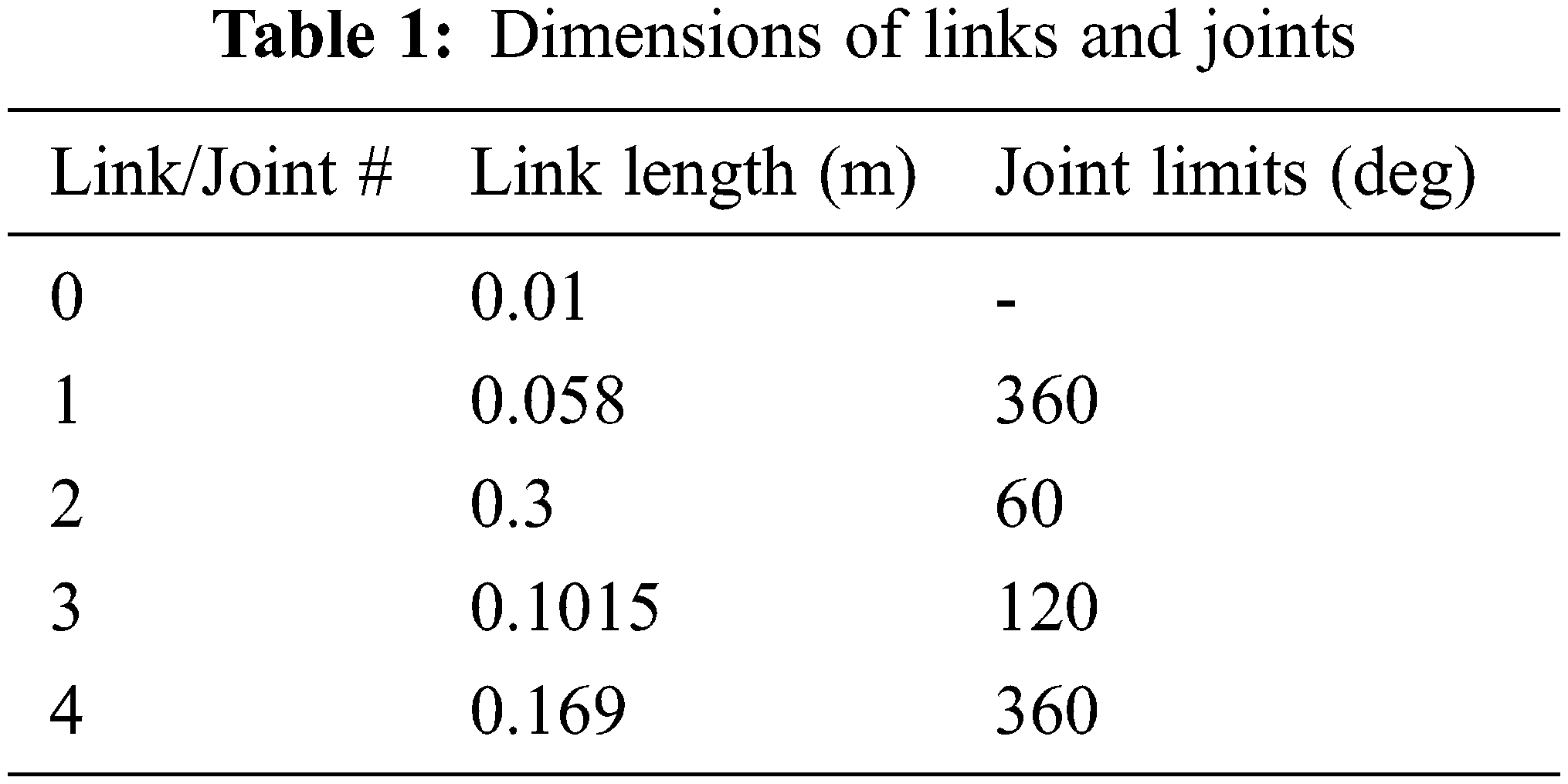
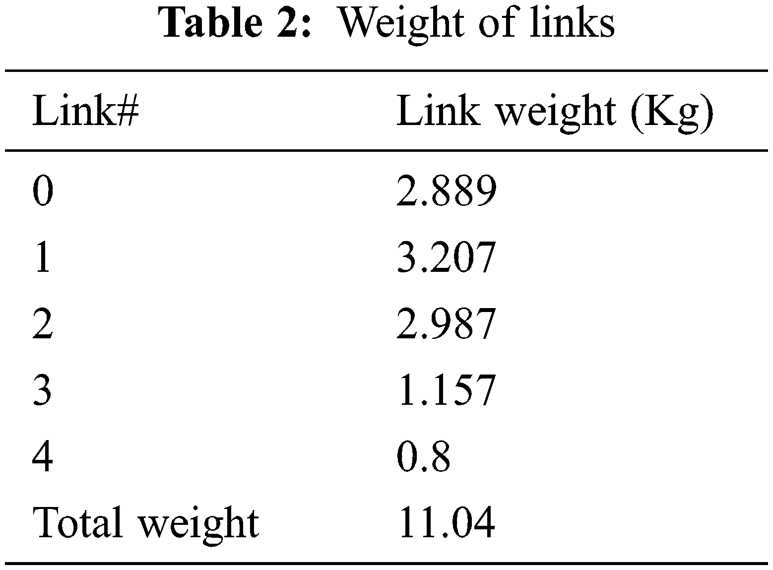
These dimensions were chosen based on the dental chair specifications and anthropomorphic data. Moreover, these dimensions would be further optimized through motion simulation by generating the required workspace in which the dental procedures need to be performed by the dental piece. The entire design of the manipulator was carried out using the Solidworks software. We chose aluminium for the prospective product fabrication and the same is considered for the simulation. The Aluminium material has several favourable properties such as good durability, strength, corrosion resistance and cost effectiveness. Besides, it is generally the ready-to-go material for the machining/manufacturing of robots. The weights of each link calculated with aluminium as chosen material are given in Tab. 2.
3.2 Preparation of CAD Model for Exporting it to Simscape/Simulink
The CAD model prepared using the Solidworks has to be exported to Simscape/Simulink in order to perform motion simulations. Before exporting the CAD model to Simulink, it is necessary to simplify the model by keeping the joints and links that would contribute to the motion simulation. This is done by combining all the secondary parts to a main part or link (Secondary parts implies nuts, bolts, washers, etc.). The simplified CAD model is shown in Fig. 2e. The simplified Solidworks model is then exported to Simulink using the Simscape Multibody Link Add-on. Imported model under Simscape environment is shown in Fig. 3a, and this model is otherwise called as physical model. As this physical model was created just from the manipulator CAD model and hence it has the definition for only the solid elements of structure. However, for simulating the motion of the manipulator, this model should be added with the control definition and this is explained in subsequent sections.
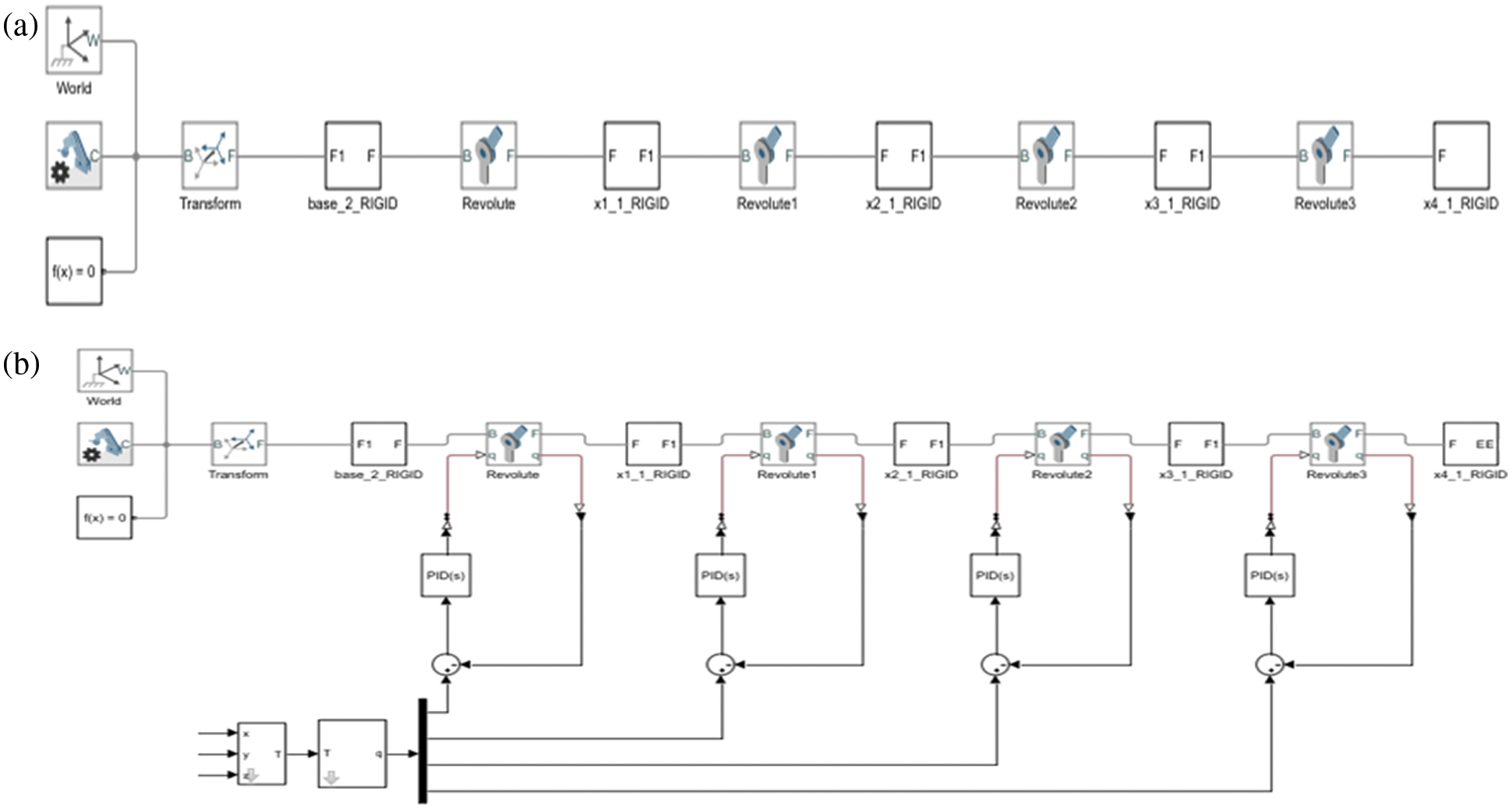
Figure 3: The physical model of the designed manipulator: (a) The physical model of the manipulator resulted after the simplified CAD model is imported under Simscape environment, (b) The overall physical model of the manipulator with Proportional Integral and Derivative (PID) controller, trajectory planner and scopes for observing various parameters of multi-body motion simulation
3.3 Kinematic and Dynamic Models
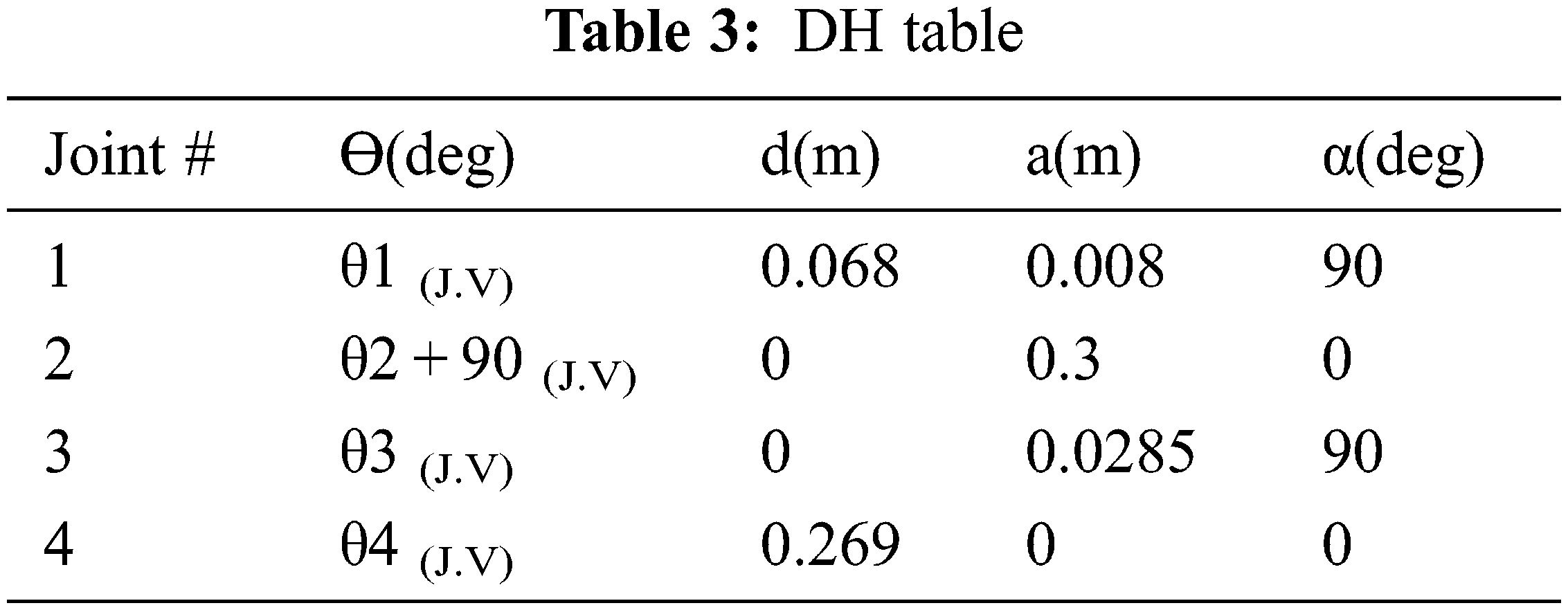
In this section, the kinematic and dynamic models are derived. To do so, defining various coordinate systems and transformation from one to another is important. Considering the overall dental implantation system, coordinate systems can be built to the robot, robot tool, surgical guide and oral cavity, and the transformation matrices to transfer from one coordinate system to another can also be derived. However, this work focuses only on the manipulator, therefore coordinate systems or frames are defined to each link of the manipulator and transformation matrices are derived using the Denavit Hartenberg (DH) formulation. To define coordinate systems to the manipulator, the simplified CAD model showing the links distinctly is obtained as shown in Fig. 2f. Then, the frames are assigned to each link as per DH approach. The details of frames are shown in Fig. 2g. Finally, the DH parameters are obtained as given in the Tab. 3.
The homogeneous transformation matrices are given below:
For the link-1,
For the link-2,
For the link-3,
For the link-4,
>> roblocks
We used the robotics toolbox for determining the inverse kinematics of the manipulator. In order to account for the forces and torques involved, we must obtain the Jacobians or dynamic models. To calculate the joint torques, the Jacobians are required and are derived in this section. The Jacobian matrix is of 6*4 sizes and is given in Eq. (5). Each element of this matrix contained several terms, hence we presented it column wise. Besides, the equation that relates joint velocities to the tool velocity in Cartesian space is derived using the Jacobian as given in Eq. (6). Furthermore, the relationship between the end effector force vector and joint torques is given in Eq. (7).
3.4 Motion Planning and Control
In this section, we briefly describe about adding PID controller as a trajectory tracker and polynomial trajectory planner to the physical model obtained of the manipulator in the previous section. Fig. 3b is the final model in which the trajectory planner is added to the model. The polynomial trajectory block is responsible for generating the trajectory by using three inputs; time, waypoints and time points. Time is equal to simulation time. Waypoints are points where the user wants the end-effector to reach and time points are the time at which the robot should reach the mentioned points. The block outputs position, velocity, and acceleration for the respective time. The dimension of waypoints vector is always 3 × N where 3 implies x, y, z and N implies the number of points the robot has to reach. Initial conditions are zero and the equation is a cubic polynomial. The dimension of time points vector is always a row vector with times values in seconds and the number is equal to the number of waypoints.
The models were created and simulated in Solid works and MATLAB/Simulink software on a Dell laptop with i7 8th Gen processor and 16 GB Random Access Memory (RAM). In order to validate the feasibility of the robot, we conducted several trials of simulations in different scenarios which are detailed further. Note that a random noise with amplitude in the range of 10−5 was inserted into the model to account for the sensors and modelling uncertainties. This was used while performing simulations in all the scenarios that we considered in this work.
Since the manipulator was designed considering the specifications of the dental chair and the average heights of humans when seated on it, the work volume of the manipulator has to encompass all possible locations of the mouth and the implant sites in it. Therefore, the workspace of the manipulator was generated in simulation by incorporating the designed link lengths and joint limits on MATLAB. The resulting workspace of the manipulator is almost spherical shaped and is shown in Fig. 4.
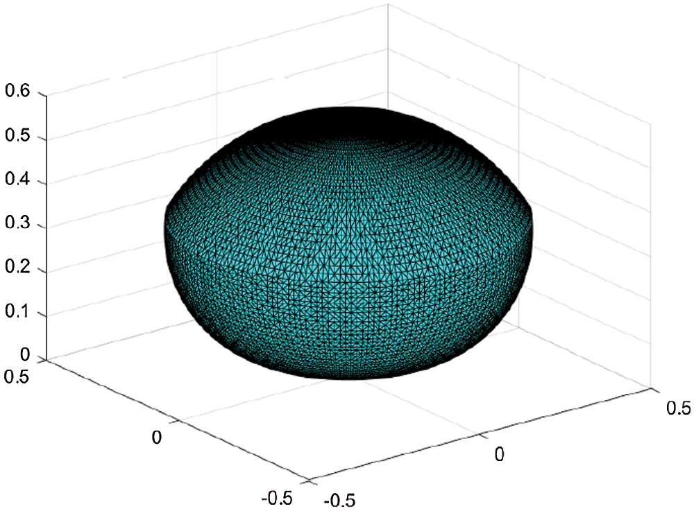
Figure 4: The spherical workspace of the manipulator encompassing the possible oral volume in which implantation can be done, where x, y and z axes values are in m
The total work volume computed through simulation is 0.2057 m3 and it was also validated analytically. It is also verified that this workspace is sufficient enough to let the dental hand piece maneuver within the mouths of people of different heights.
4.2 Positioning and Trajectory Tracking Efficiency
In order to analyse the positioning accuracy as in [22] the repeatability test was conducted by making the manipulator to reach a same known position repeatedly for 10 trials and the mean values are 0.0045, 0 and 0.0028 along x, y and z-axis respectively in m. Furthermore, for analysing the trajectory tracking efficiency, a set of trials was conducted in two different scenarios. In the first scenario, we assumed that the hand piece would be manually dragged somewhat closer to the point that lies between two incisors as can be seen in Fig. 5 and then the manipulator would automatically position itself to the point accurately enough with the feedback as in [21] or using surgical guide. Considering this point as a reference on the oral coordinate system, trajectories are then planned for each tooth and executed. This scenario was simulated for 10 trials and the mean positioning errors along each axis are given in Tab. 4.
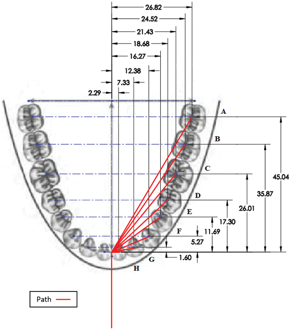
Figure 5: Trajectories executed by the robot (Courtesy: The base image was obtained from Wikipedia and the red color overlaid traces imply the trajectories tracked by the drill bit.)
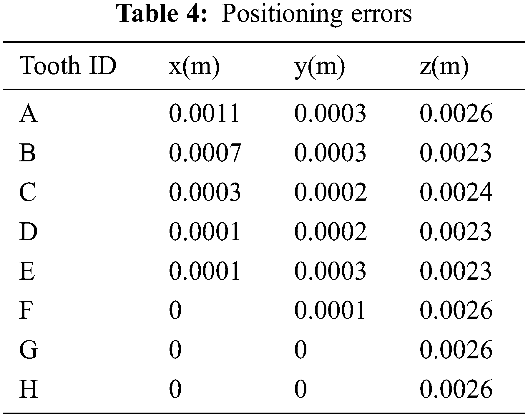
The same results are also plotted in Figs. 6a and 6b. Based on these results, it can be inferred that as the distance to the commanded position increases, the positioning error slightly diverges. It can however be treated as a systematic error and overcome.
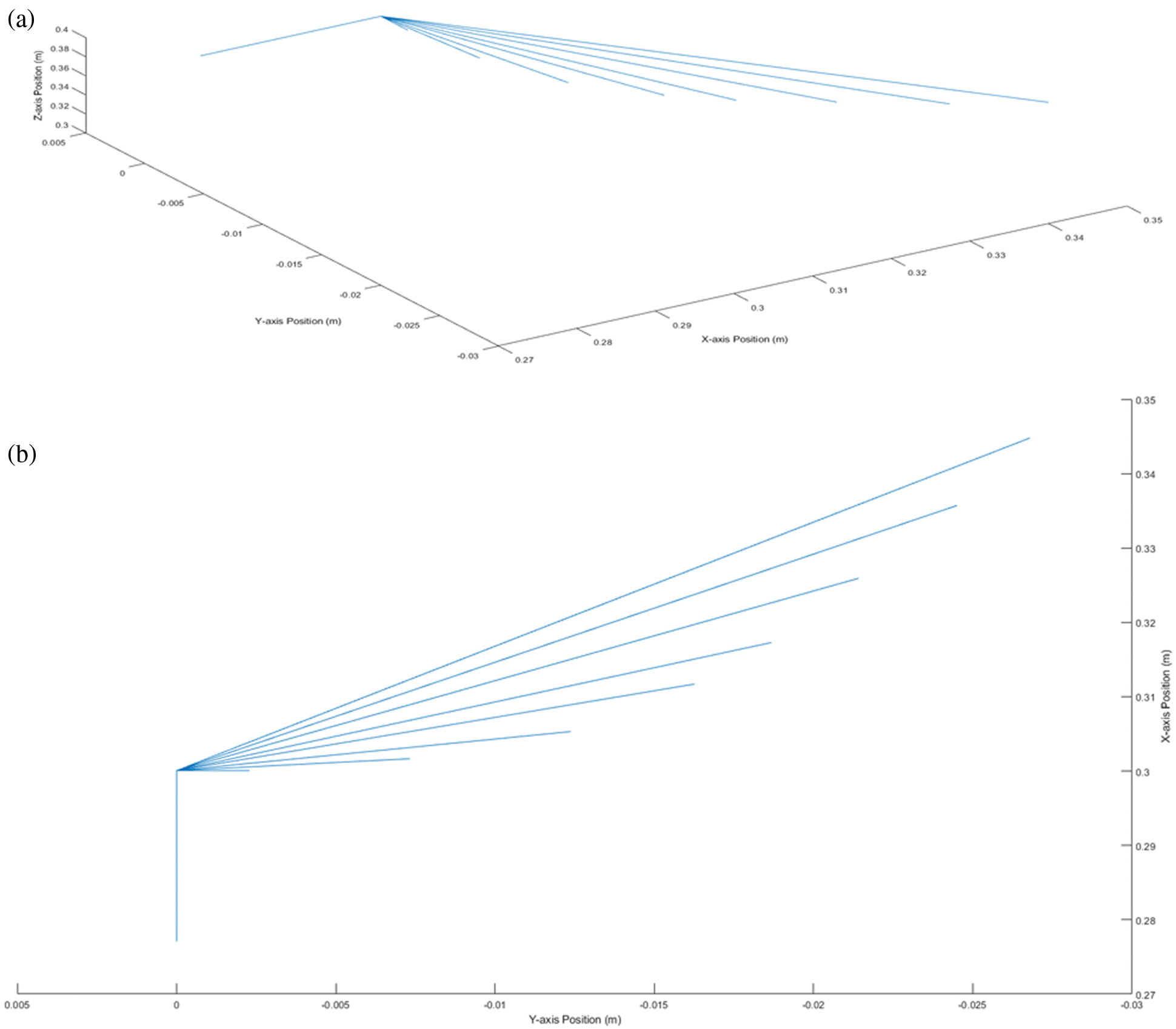
Figure 6: Trajectories of the end effector: (a) 3D sketch of the trajectories tracked by the end effector, where x, y and z axes are with position coordinate values in m, (b) 2D sketch of the trajectories tracked by the end effector
In the second scenario, the drill bit was commanded to track the trajectory planned from the right wisdom tooth to the left one passing through all the way-points (here all teeth locations) lying between these two extremes. The trajectories (position, velocity, acceleration and torque) of each joint are plotted in Figs. 8a–8d. In addition, the trajectories tracked by the drill bit in Cartesian space are also shown in Figs. 9a–9c. These results confirm that the manipulator is able to track the planned trajectories accurately enough with a tracking error less than 2%.
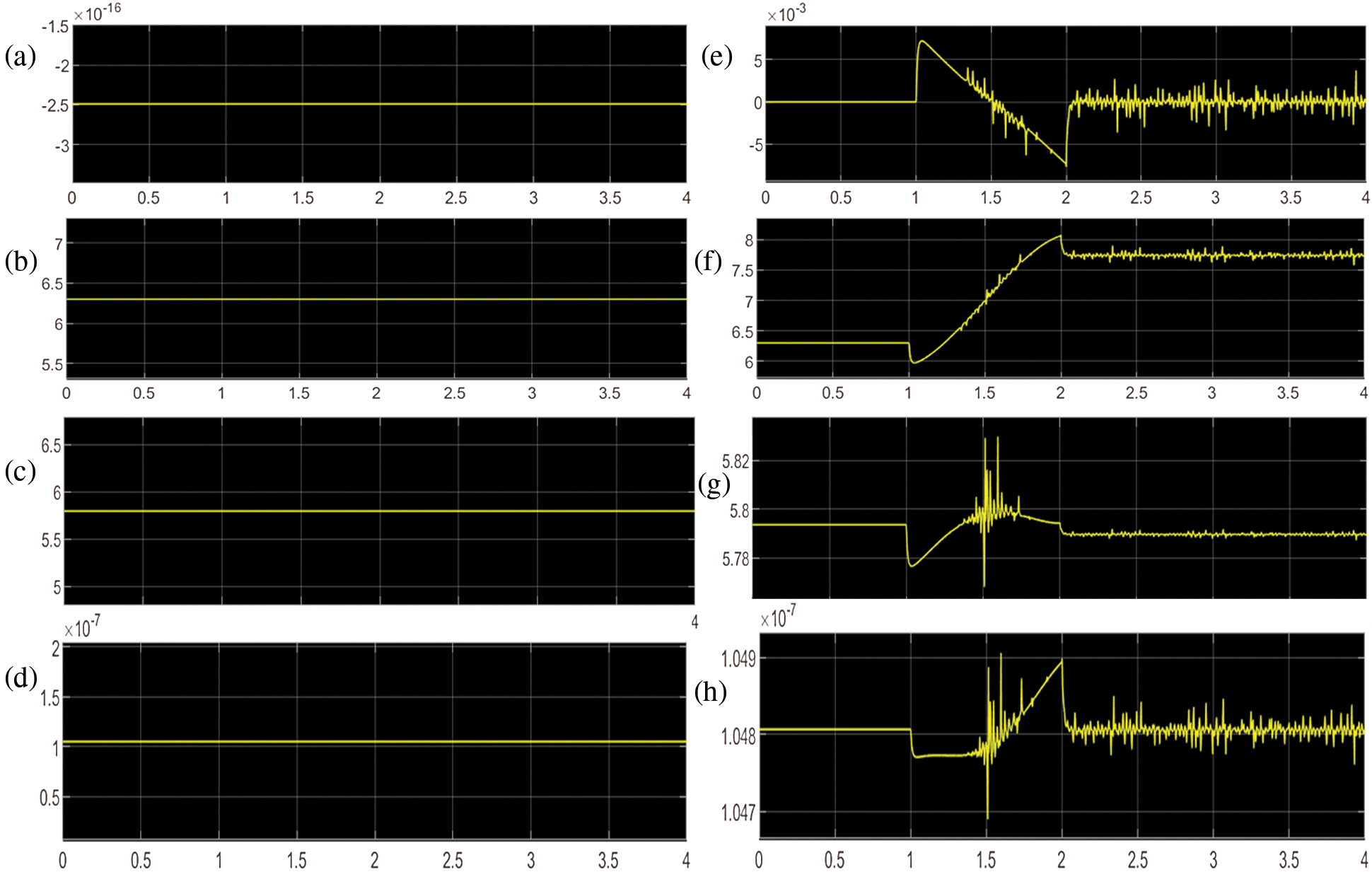
Figure 7: Static torque of joints: (a) Static torque (Nm) of joint-1, (b) Static torque (Nm) of joint-2, (c) Static torque (Nm) of joint-3, (d) Static torque (Nm) of joint-4, (e) Dynamic torque (Nm) of joint-1, (f) Dynamic torque (Nm) of joint-2, (g) Dynamic torque (Nm) of joint-3, (h) Dynamic torque (Nm) of joint-4
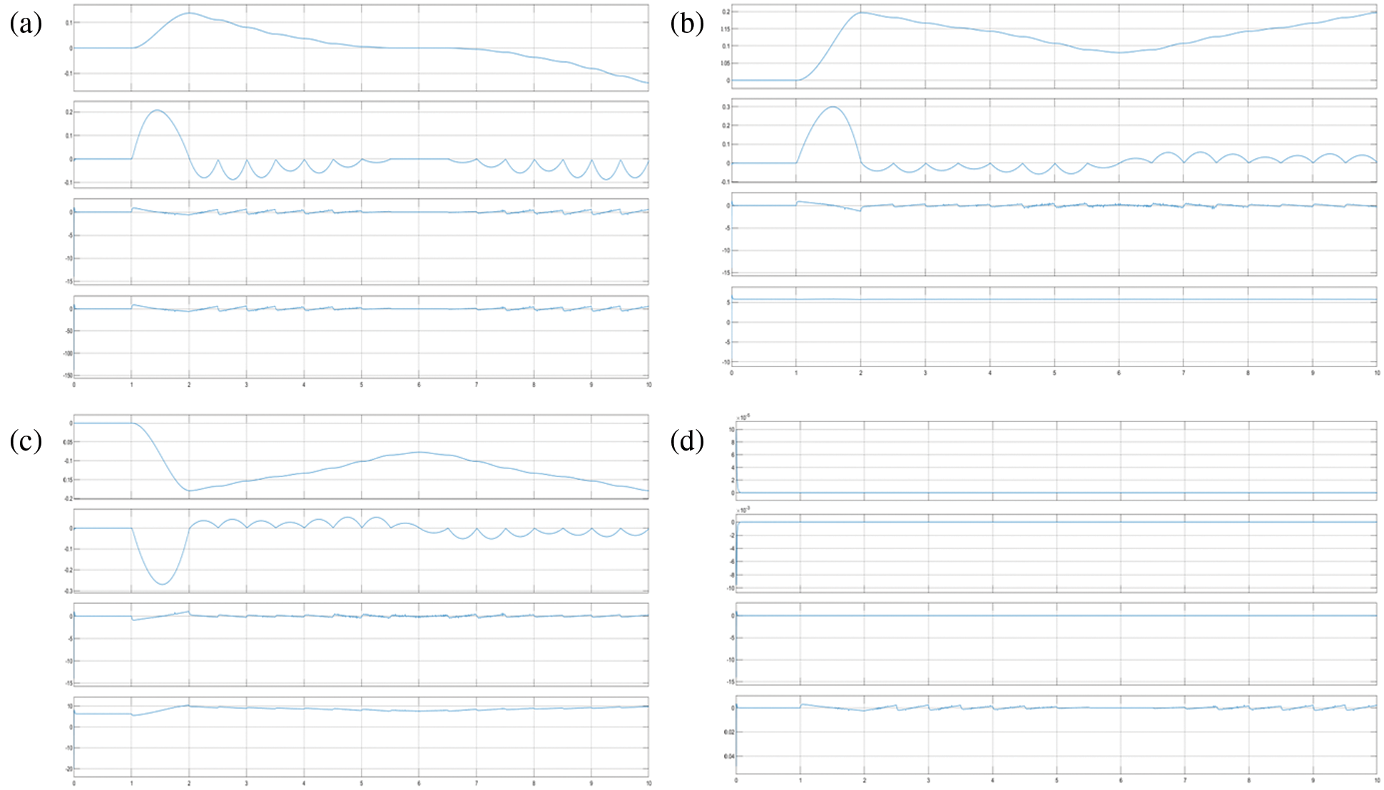
Figure 8: Trajectories in the joints space: (a) Trajectory plot of the revoulte joint-1 when the tip of the drill moving from the right wisdom tooth to the left one, where the trace-1 is angular position (rad), trace-2 is velocity (rad/s), trace-3 is acceleration (rad/s2) and trace-4 is torque (Nm) with respect to time(s) from top to bottom, (b) Trajectory plot of the revoulte joint-2 when the tip of the drill moving from the right wisdom tooth to the left one, where the trace-1 is angular position (rad), trace-2 is velocity (rad/s), trace-3 is acceleration (rad/s2) and trace-4 is torque (Nm) with respect to time(s) from top to bottom, (c) Trajectory plot of the revoulte joint-3 when the tip of the drill moving from the right wisdom tooth to the left one, where the trace-1 is angular position (rad), trace-2 is velocity (rad/s), trace-3 is acceleration (rad/s2) and trace-4 is torque (Nm) with respect to time(s) from top to bottom, and (d) Trajectory plot of the revoulte joint-4 when the tip of the drill moving from the right wisdom tooth to the left one, where the trace-1 is angular position (rad), trace-2 is velocity (rad/s), trace-3 is acceleration (rad/s2) and trace-4 is torque (Nm) with respect to time(s) from top to bottom
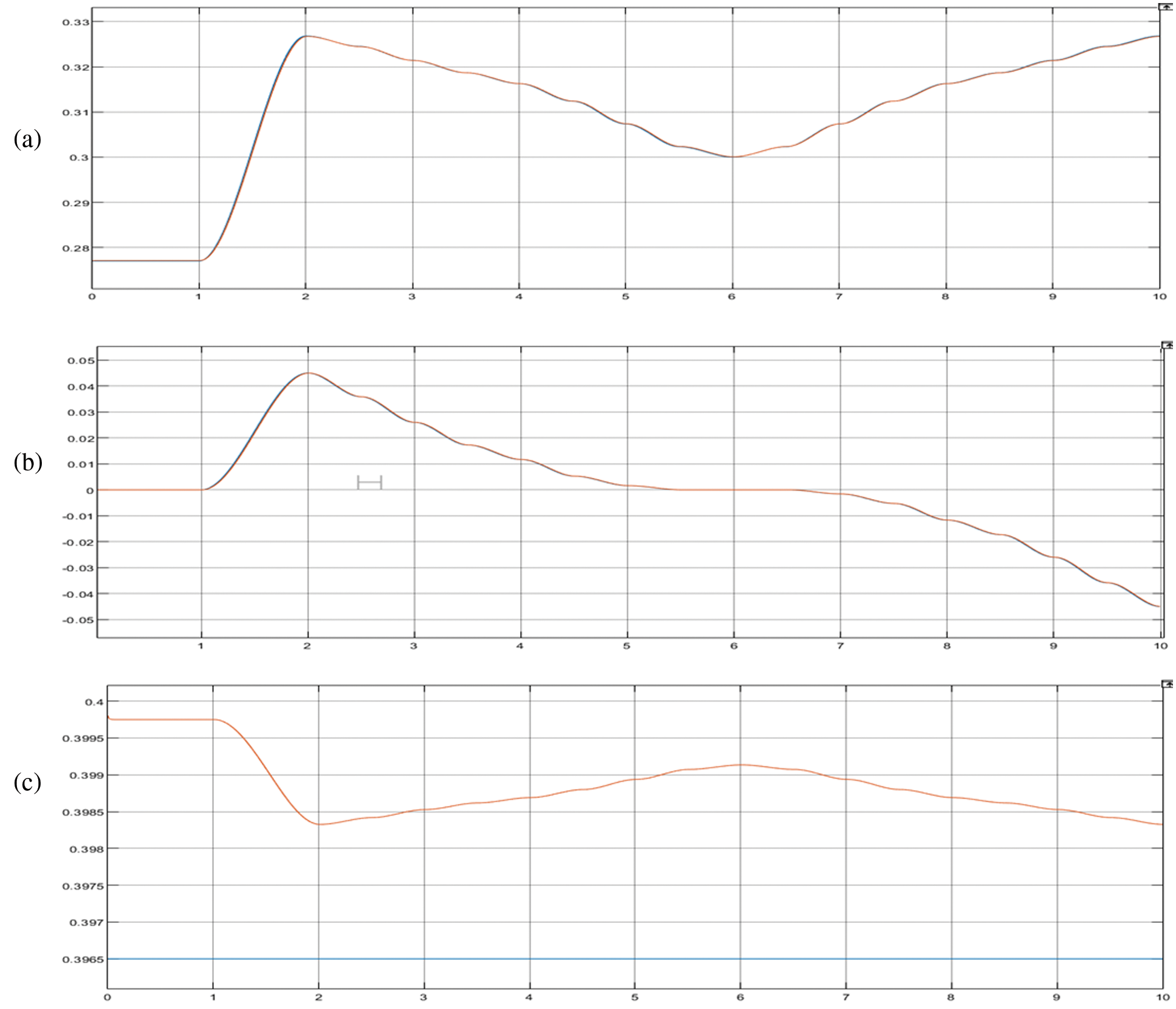
Figure 9: Trajectories in the cartesian space: (a) Trajectory along x-axis (position(m)) with respect to time(s), (b) Trajectory along y-axis (position(m)) with respect to time(s), (c) Trajectory along z-axis (position(m)) with respect to time(s)
With an aim to size the motors for joints actuation, we carried out simulations in three different scenarios. A payload of 5 kg was included which is the typical payload used with any dental robot. In the first scenario, the manipulator is assumed to be still at its home position and the static torques are simulated as shown in Figs. 7a–7d. In addition, the theoretical torques were calculated using the Eq. (4) and are equal to 0, 6.1510, 6.1510 and 0 Nm for the joints 1, 2, 3 and 4 respectively. The torques observed in the physical model simulated in Simulink at the same position are 0, 0.622, 0.622 and 0 Nm for joint 1, 2, 3 and 4 respectively. Note that the position of end-effector is at (0.277, 0, 0.3965) m.
In the second scenario, the robot was commanded to move its end-effector to a point [0.3, 0, and 0.3965] m from home position and dynamic torques were obtained in simulation as well as calculated. The theoretical torques calculated for this position are 0, 6.6771, 6.1488 and 0 Nm for joint 1, 2, 3 and 4 respectively, while the torques observed in the physical model simulated in Simulink at the same position are 0, 7.44, 5.790 and 0 Nm for joint 1, 2, 3 and 4 respectively as shown in Figs. 7e–7h. As there was no option to add the weights of each links separately in the theoretical equation, the total weight of all links was added along with the payload to calculate the torques. This must be the reason behind the difference in values between simulated and calculated torques.
The third scenario is already presented in the previous section where the last plot in every figure is the torque profile of the corresponding joint with respect to time while the end-effector traverses from the right wisdom tooth to the left via the midpoints of all other teeth lying in between. Based on these simulation results, it is clear that the customized robot meets all the functional requirements satisfactorily. Besides, the accuracy and repeatability are also within acceptable levels. Nonetheless the model still has room for several improvements. In particular, to use this manipulator model in a digital twin of the dental implantation system, the real-time constraints should be further studied and improved.
5 Conclusions and Further Work
In this paper, a customized manipulator for performing various dental implantation procedures was introduced. Unlike the existing designs, the proposed manipulator was customized to fit onto the existing dental chairs easily. We considered the relevant dental chair specifications and anthropomorphic data to ensure that the manipulator work space encompasses the drill sites that may vary based on the height of patients. Through MBD approach, the design of the manipulator was substantially improved in a way that it is not only compact and user-friendly but also reasonably accurate. This trade-off could be attributed to the MBD approach. Furthermore, the exhaustive simulation suggests that the manipulator design is functionally complete and it can be built as a prototype to further check its performance in real.
There are several avenues to improve this work. First of all, the proposed design could be developed as a physical prototype and validated. In addition, models for the remaining sub systems can also be created to build the overall digital twin of the dental implantation system. With learning techniques, it may be possible to improve the trajectory generation and tracking efficiency of the manipulator and the overall processes involved.
Funding Statement: The authors received no specific funding for this study.
Conflicts of Interest: The authors declare that they have no conflicts of interest to report regarding the present study.
1. N. J. Kassebaum, E. Bernabé, M. Dahiya, B. Bhandari, C. J. L. Murray et al., “Global burden of untreated caries,” Journal of Dental Research, vol. 94, no. 5, pp. 650–658, 2015. [Google Scholar]
2. G. C. Mejia, H. W. Elani, S. Harper, W. Murray Thomson, X. Ju et al., “Socioeconomic status, oral health and dental disease in Australia, Canada, New Zealand and the United States,” BMC Oral Health, vol. 18, no. 1, pp. 176, 2018. [Google Scholar]
3. T. Vos, A. A. Abajobir, C. Abbafati, K. M. Abbas, K. H. Abate et al., “Global, regional, and national incidence, prevalence, and years lived with disability for 328 diseases and injuries for 195 countries, 1990–2016: A systematic analysis for the global burden of disease study 2016,” in The Lancet (British Edition), vol. 390, no. 10100, pp. 1211–1259, 2017. [Google Scholar]
4. J. Ramos-Jorge, I. A. Pordeus, M. L. Ramos-Jorge, L. S. Marques and S. M. Paiva, “Impact of untreated dental caries on quality of life of preschool children: Different stages and activity,” Community Dentistry and Oral Epidemiology, vol. 42, no. 4, pp. 311–322, 2014. [Google Scholar]
5. A. Sheiham and R. G. WattSheiham, “The common risk factor approach: A rational basis for promoting oral health,” Community Dentistry and Oral Epidemiology, vol. 28, no. 6, pp. 399–406, 2000. [Google Scholar]
6. B. Varenne, “Integrating oral health with non-communicable diseases as an essential component of general health: WHO's strategic orientation for the African region,” Journal of Dental Education, vol. 79, no. 5, pp. S32–S37, 2015. [Google Scholar]
7. A. Alrahlah, R. Khan, K. Alotaibi, Z. Almutawa, H. Fouad et al., “Simultaneous evaluation of creep deformation and recovery of bulk-fill dental composites immersed in food-simulating liquids,” Materials, vol. 11, no. 7, pp. 1180, 2018. [Google Scholar]
8. B. Karahalil, E. Kadioglu, A. M. Tuzuner-Oncul, E. Cimen, E. Emerce et al., “Micronucleus assay assessment of possible genotoxic effects in patients treated with titanium alloy endosseous implants or miniplates,” Mutation Research Genetic Toxicology and Environmental Mutagenesis, vol. 760, pp. 70–72, 2014. [Google Scholar]
9. L. Gaviria, J. P. Salcido, T. Guda and J. L. Ong, “Current trends in dental implants,” Journal of the Korean Association of Oral and Maxillofacial Surgeons, vol. 40, no. 2, pp. 50–60, 2014. [Google Scholar]
10. J. Li, W. Y. H. Lam, R. T. C. Hsung, E. H. N. Pow and Z. Wang, “A customizable, compact robotic manipulator for assisting multiple dental procedures,” in 3rd Int. Conf. on Advanced Robotics and Mechatronics (ICARM), Singapore, pp. 720–725, 2018. [Google Scholar]
11. J. L. Ortiz Simon, A. M. Martinez, D. L. Espinoza and J. G. Romero Velazquez, “Mechatronic assistant system for dental drill handling,” The International Journal of Medical Robotics Computer Assisted Surgery, vol. 7, no. 1, pp. 22–26, 2011. [Google Scholar]
12. R. G. Watt, “Strategies and approaches in oral disease prevention and health promotion,” Bulletin of the World Health Organization, vol. 83, no. 9, pp. 711–718, 2005. [Google Scholar]
13. M. Tallarico, R. Scrascia, M. Annucci, S. M. Meloni, A. I. Lumbau et al., “Errors in implant positioning due to lack of planning: A clinical case report of new prosthetic materials and solutions,” Materials, vol. 13, no. 8, pp. 1883, 2020. [Google Scholar]
14. R. Nishat, S. Ramachandra, S. S. Behura and H. Kumar, “Digital cytopathology,” Journal of Oral and Maxillofacial Pathology, vol. 21, no. 1, pp. 99–106, 2017. [Google Scholar]
15. T. Tanzawa, K. Futaki, C. Tani, T. Hasegawa, M. Yamamoto et al., “Introduction of a robot patient into dental education,” European Journal of Dental Education, vol. 16, no. 1, pp. e195–e199, 2012. [Google Scholar]
16. M. Rawtiya, K. Verma, P. Sethi and K. Loomba, “Application of robotics in dentistry,” Indian Journal of Dental Advancements, vol. 6, no. 4, pp. 1700–1706, 2014. [Google Scholar]
17. V. Carlsson, M. Hakeberg, K. Blomkvist and U. Wide Boman, “Orofacial esthetics and dental anxiety: Associations with oral and psychological health,” Acta Odontologica Scandinavica, vol. 72, no. 8, pp. 707–713, 2014. [Google Scholar]
18. F. Duttenhoefer, M. A. Fuessinger, Y. Beckmann, R. Schmelzeisen, K. A. Groetz et al., “Dental implants in immunocompromised patients: A systematic review and meta-analysis,” International Journal of Implant Dentistry, vol. 5, no. 1, pp. 1–12, 2019. [Google Scholar]
19. M. Goellner, J. Schmitt, M. Karl, M. Wichmann and S. Holst, “The effect of axial and oblique loading on the micromovement of dental implants,” The International Journal of Oral & Maxillofacial Implants, vol. 26, no. 2, pp. 257–264, 2011. [Google Scholar]
20. K. -J. Cheng, T. -S. Kan, Y. -F. Liu, W. -D. Zhu, F. -D. Zhu et al., “Accuracy of dental implant surgery with robotic position feedback and registration algorithm: An in-vitro study,” Computers in Biology and Medicine, vol. 129, pp. 104153, 2021. [Google Scholar]
21. M. Gouasmi, M. Ouali, B. Fernini and M. H. Meghatria, “Kinematic modelling and simulation of a 2-R robot using solidworks and verification by MATLAB/simulink,” International Journal of Advanced Robotic Systems, vol. 9, no. 6, pp. 245, 2012. [Google Scholar]
22. T. -M. Sun, H. -E. Lee and T. -H. Lan, “Comparing accuracy of implant installation with a navigation system (NSa laboratory guide (LGNS with LG, and freehand drilling,” International Journal of Environmental Research and Public Health, vol. 17, no. 6, pp. 2107, 2020. [Google Scholar]
 | This work is licensed under a Creative Commons Attribution 4.0 International License, which permits unrestricted use, distribution, and reproduction in any medium, provided the original work is properly cited. |