DOI:10.32604/iasc.2023.026868
| Intelligent Automation & Soft Computing DOI:10.32604/iasc.2023.026868 | |
| Article |
Modeling Target Detection and Performance Analysis of Electronic Countermeasures for Phased Radar
1Faculty of Electronics Engineering, Sathyabama Institute of Science and Technology, Chennai, 600119, India
2Department of Electronics and Communication Engineering, KPR Institute of Engineering and Technology, Coimbatore,641048, India
3Sathyabama Institute of Science and Technology, Chennai, 600119, India
*Corresponding Author: B. Sheela Rani. Email: kavisheela66@gmail.com
Received: 06 January 2022; Accepted: 17 February 2022
Abstract: Interference is a key factor in radar return misdetection. Strong interference might make it difficult to detect the signal or targets. When interference occurs in the sidelobes of the antenna pattern, Sidelobe Cancellation (SLC) and Sidelobe Blanking are two unique solutions to solve this problem (SLB). Aside from this approach, the probability of false alert and likelihood of detection are the most essential parameters in radar. The chance of a false alarm for any radar system should be minimal, and as a result, the probability of detection should be high. There are several interference cancellation strategies in the literature that are used to sustain consistent false alarms regardless of the clutter environment. With the necessity for interference cancellation methods and the constant false alarm rate (CFAR), the Maisel SLC algorithm has been modified to create a new algorithm for recognizing targets in the presence of severe interference. The received radar returns and interference are simulated as non-stationary in this approach, and sidelobe interference is cancelled using an adaptive algorithm. By comparing the performance of adaptive algorithms, simulation results are shown. In a severe clutter situation, the simulation results demonstrate a considerable increase in target recognition and signal to noise ratio when compared to the previous technique.
Keywords: Sidelobe canceller; sidelobe blanking; constant false alarm rate; clutter; jammer cancellation ratio; probability of detection
To reduce interference arriving through sidelobe, modern radars employ a variety of electronic countermeasures. A radar can use the partition to smother the obstruction without suffocating the target return when the ideal goal and the obstruction source are not in the same area. A radar receiving equipment with a radiation design that delivers a high rise in the target’s course and a very low response in the impedance bearing can achieve this precise camouflage. Controlling the status of a reception equipment radiation design may be done in a few ways. Fixed gap enlightenment can offer an example with consistently low sidelobes beyond the principal bar’s bearing, for example. This type of example is useful for suppressing both obstacle and mess. The radiation-design sidelobe level conveyed in connection with isotropic increase, which is the addition of a lossless radio wire that transmits uniformly in all directions, is a significant barrier in low-sidelobe configuration. Electrically large, high-gain radio wires can achieve radiation designs with sidelobes that are low about the pinnacle again, but not as for the isotropic level, without undue difficulty. When the top rise is constrained by physical gap size requirements, as it is in most radar receiving systems, the optimal sidelobe level is frequently much below isotropic. Low isotropic sidelobe levels might be difficult to achieve due to the need for highly precise gap brightening (depicted in the following segment, “Azimuth Beamforming”). When gap light errors are coupled with gap light on the inside, they become a lot more common. Versatile nulling is another method for removing impedance. In the example, a flexible reception device creates nulls only in the zones of interferers. When the essential long-haul brightening resilience for fixed organizations become impractical, or when the beamwidth increment and misery associated with extreme gap tightens can’t be accommodated, versatile nulling is a particularly appealing option [1].
Another sidelobe canceler (SLC) computation for radar is introduced, with the following two important properties: 1) variable retraction of blockage entering the sidelobes of the major shaft of the radar receiving wire, and 2) independence of identification limit and obstruction level. Property 2 has the appealing side effect of keeping the choice limit and bogus caution likelihood constant even when the information signal-to-noise ratio (SNR) varies. This is the Constant False Rate (CFAR) attribute in action. The impedance [2] overwhelms the information provided by the SNR in this application.
The CFAR SLC is a radar computation that is thought to help with solid detection of radar echoes (target localization) under non-stationary impedance conditions [3]. In addition, the impedance is intended to be Gaussian, with second-request insights that vary in time at a rate almost equivalent to the term of the transmitted radar beat.
Radar jammer signals are genuinely a consideration in terms of desired influence on trapped structure and jammer abilities. Location hiding is one of the most used radar sticking tactics. The sticking of observation radar is commonly predicted to suffocate global recognition, and the jammer continuously provides the sticking indication [4,5]. Sticking signs are frequently noisy, but they get the job done most of the time when they are timed to the radar signal at the finder (adequate spillage).
Transmission of the sticking sign and (at least locally) steady heading of appearance of the sticking sign are two of these limitations. This may be used to hide signs that are stuck to the wall [6]. The idea of concealing sticking signs is based on the flexible shape of new reception apparatus radiation design by the versatile comprehensible addition of basic radar receiving wire signal with the sign of helper reception apparatuses [7,8]. The new radiation example should result in significant jammer minima. This is referred to as a sidelobe canceller computation (SLC).
SLC computations can smother sticking indications just within reception apparatus sidelobes, even though sticking signs limit radar discovery execution in both the mainlobe and sidelobes of radar reception apparatus. Sticking indicators in the main lobe cannot be suppressed since they are entirely correlated with intrigue signals (targets). By combining CFAR with a considerable increase in the reference channel for enhancing signal to noise ratio, the suggested solution based on adaptive sidelobe cancellation and blanking reduces the chance of false alarm. The research begins with an overview of well-known Sidelobe Cancellation (SLC) strategies for 2D radar receivers with mandatory receiving wires [9].
The following diagram depicts the structure of the paper: Sections 2 and 3 deal with sidelobe cancellation and sidelobe blanking methods, Section 4 with performance analysis and comparative findings, and Section 5 with mathematical modelling of the target signal. Structure No. 2
De Witt et al. [10] developed a fast DL re-constructor that takes use of video’s spatiotemporal properties. They focused on convolution gated recurrent units, which have reduced memory requirements. The projected recurrent network improves reconstruction quality over static approaches that recreate video frames separately, according to these simulations. For reconstructing the picture from their CS measurement, Chithambaramani et al. [11] presented a novel DR2 - Net. The DR2 -Net is based on two theories: 1) residual learning may improve reconstruction quality further, and 2) linear mapping can reconstruct higher quality original pictures. Consequently, DR2 -Net is divided into two modules: residual network and linear mapping network. The linear mapping network is specifically executed by the FC layer in NN.
Sun et al. [12] take use of learning-based algorithms for video super resolution (SR) fields, and this paper proposes a new video SR reconstruction approach based on Deep convolutional neural networks (DCNN) and Spatio-Temporal Convolutional Neural Network-Super Resolution (STCNN-SR). It might be a Deep Learning approach for reconstructing video SR, which presupposes a mapping relationship between related High Resolution (HR) and Low Resolution (LR) picture blocks, as well as redundant information and spatio-temporal non-local complements between close LR video frames. The optical flow is given in the DL network, whereas Chen et al. [13] introduced a super-resolution (SR) reconstruction approach based on an effective subpixel CNN. In addition, following the Deep Convllution Network (DCN), a super pixel convolutional layer is added to improve the SR. Satpathy et al. [14] demonstrate DL utilizing convolution AE networks to recover real world 128 128-pixel footage at thirty frames per second from single pixel camera sampling at a compression ratio of 2%. Furthermore, by training the network on a large database of pictures, the first layer of the convolution networks is optimized, which is equivalent to optimizing the basis used to scan the image intensities. By learning from a single occurrence of a specific setting, Ramalingam et al. [15] reveals the potential of HR for task-specific adaptation, which has applications in metrology, gas sensing, and 3D imaging.
Two DL modules were used by Chitambaramani et al. [16] to improve the spatial resolution of temperature regions. In MPSRC, the three pathways with and without a pooling layer are targeted at fully capturing the temperature spatial distribution characteristic. The appropriate HR temperature regions have been successfully and precisely rebuilt. Sundaram et al. [17] investigate a new foveated reconstruction method based on recent advances in generative adversarial NN. They created a believable peripheral video by reassembling each frame from a smaller percentage of pixels. When compared to sophisticated foveated rendering, this approach is quite good at providing a visual experience with minimal quality compromise.
3.1 Sidelobe Cancellation Algorithm
With gauged indicators of assistant reception devices, a sidelobe canceller (SLC) suppresses unwanted interference from the primary antenna. The weights of the radar framework’s auxiliary and main antennas must be evaluated in a flexible manner. Fig. 1 illustrates the activity of the sidelobe canceller. Fig. 2 depicts a generic SLC block diagram. Main lobe signals are virtually unaffected since the extension of fundamental receiving wire exceeds the addition of helper reception equipment.
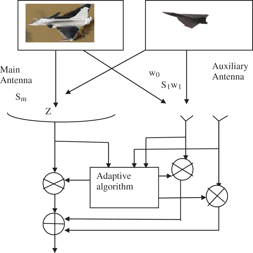
Figure 1: Generalized sidelobe canceller
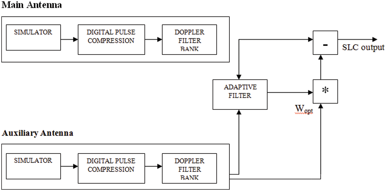
Figure 2: Block diagram of sidelobe cancellation
The primary channel is used to receive radar data from the receiver. At least one of the system’s components, state K, is defined as an assistance receiving wire for collecting impedance reference tests and framing an impedance covariance gauge in this way. When many helpers are used, the calculated covariance lattice contains exact impedance data. As shown by a CFAR calculation, information obtained in the primary channel is combined with information obtained in the reference channels, and a decision is made as to whether a target has been identified at a certain range and Doppler.
In [18] illustrates how to calculate SLC. To reduce interference, the signals from the main and auxiliary antennas are digitally compressed and doppler filtered, and the weights are adaptively updated. SLC is designed to counter electronic attack (EA) and jamming. Because of the extreme clutter, the EA signal is often assumed to be a noise-like interference signal with a transmission capacity that exceeds the target signal. Fig. 2 illustrates how SLC reduces blockage entering the radar via the receiving wire sidelobes.
The sidelobes of the radar receiving equipment sidelobes are duplicated by the auxiliary radio wires. Furthermore, the assistant reception apparatuses are placed close enough to the stage focal point of the radar receiving wire to ensure that the obstacle instances they receive are accurate. Many helper receiving cables are also necessary due to the large number of sticky signs to be covered.
The purpose of the CSLC framework is to stop the sticking, which is like a noise with a long obligation cycle that travels across the sidelobe of the radar (for example, the stalemate sticking). By picking Optimum Weights needed by space separating or receiving wire shaft shape, the assistant radio wire of the CSLC framework nulls on the course of sticking source. The success of CSLC might also be measured in terms of persistently improvement variables (or sticking scratch-off proportion called dropping proportion for short). The Jammer Cancellation Ratio (JCR) is the percentage of a unique information port's sticking force to the sidelobe scratch-off yield port’s sticking force.
There might be N-PRTs on the receiver side, and N-run cells inside each PRT. We’re going to take 16 PRTs and 5000 territorial cells shown in Fig. 3. A framework is created with just the goal in mind. Following that, receiver and jammer noises are added. The SIMULATOR block handles the complete cycle. Following that, DPC (Digital Pulse Compression) is used. The sign is convolved with the intricate form of the equivalent in DPC. Doppler Filtering is used once DPC has been completed. Fast Fourier Transform (FFT) along section savvy is used to perform the Doppler Filter Bank (DFB), which has 16 channel banks. The yield of the Doppler channel is then assigned to any flexible abrogation framework. The Least Mean Square (LMS) computation is used as a flexible retraction framework in this project. For the assistant receiving wire, a similar system is rehashed, and then sidelobe dropping is performed.
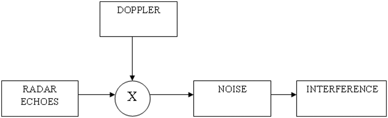
Figure 3: Radar model
Polyphase codes are those that use any agreeably connected stages based on a single major stage addition, and these codes are inferred reasonably intelligibly by recognizing a recurrence regulation heartbeat pressure waveform with also an in-proximity oscillator at the band edge of the waveform (single sideband identification) or band focus (twofold sideband discovery) and testing the resultant in-stage I and quadrature Q information at the Nyquist r.
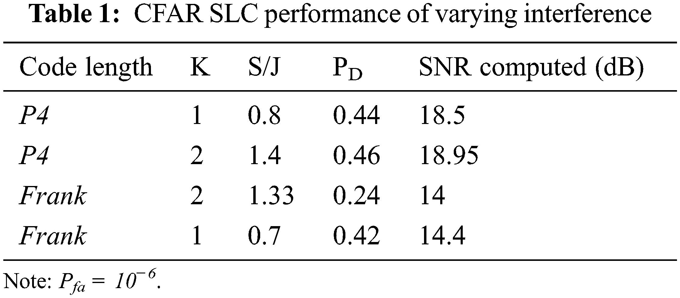
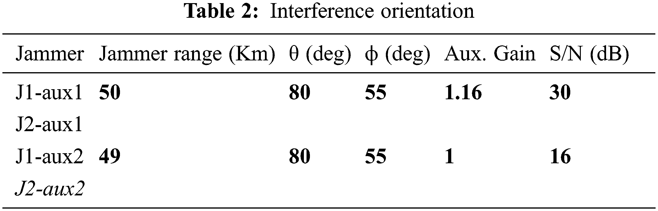
The Frank code, a polyphase code with excellent non-intermittent connection features, was proposed by Forthright. P-codes are Frank polyphase codes that are more tolerant than Frank codes when it comes to beneficiary band-restricting before beat pressure, according to Kretscher and Lewis. Lewis has shown that by following the autocorrelation with two examples sliding window subtractors for Frank and P1 codes and two examples sliding window adders for P3 and P4 codes, the sidelobes of polyphase codes may be significantly reduced after collection. Polyphase pressure codes have been created using a variety of methods, including step estimation, straight recurrence adjustment waveforms (Frank, P1, P2), and direct recurrence regulation waveforms (P3, P4). The codes are inferred by breaking the waveform into equal-length sub-codes and using a stage an incentive for each sub-code that best fits the overall stage direction of the core waveform shown in Tabs. 1 and 2.
Sending a previously coded pulse and preparing the echo to produce a sufficiently limited pulse is known as pulse compression. A long-pulse radar framework’s extended discovery capability is achieved while maintaining the thin pulse radar framework’s range goal capacity. Long pulse transmission enables for more efficient use of the radar’s normal force capability. The radar’s usual intensity might be increased without increasing the pulse redundancy recurrence (PRF), reducing the radar’s unambiguous range. The usage of lengthy pulses also results in an increased framework settling capacity in doppler imaging. Advanced pulse compression methods are often employed for both the age and coordinated filtering of radar waveforms. To regulate the sign, the advanced maker uses a specified stage-time profile. This pre-configured description is either maintained in memory or meticulously built with the help of necessary variables. A computerized correlator for any waveform or, more likely, a “stretch” technique for a direct FM waveform might be used to create the coordinated channel. Computerized pulse compression has distinct features that determine its suitability for a certain radar application. An advanced methodology’s major flaw is that its innovation is limited to data transmission rates of less than 100 MHz. This data transmission capacity restriction might be alleviated by combining recurrence augmentation with stretch preparation. For a broader run inclusion, computerized coordinated separation usually needs a few covered prepared units.
3.2 Sidelobe Blanking Algorithm
The Sidelobe Blanking (SLB) architecture was designed to prevent solid targets and obstacle pulses from accessing the radar recipient via the receiving wire sidelobes. SLB is then primarily utilized to eliminate resistance from other pulse transmissions as well as conscious pulse-like sticking. Similarly, SLB works with repeater impedances that are tolerable (CRI). The SLB design is based on two reception apparatuses: the basic radio wire and its principal flap and sidelobes, and the second is the secondary radio wire. The blanking radio wire is the next one, which adds less than the primary receiving wire’s major projection but is more noticeable than fundamental reception equipment sidelobes. The SLB logic decides whether to clear the primary radar channel for each range cell depending on a single canister’s breadth. When the fundamental channel yield exceeds the limit level, the primary channel signal is compared to the phoney caution edge considering assistant channel yield to determine whether recognition should be declared. The fundamental channel is blanked if this is not the case.
We can prevent any objective or jammer that is in the sidelobes of the main radio wire from entering the sign investigation circuits by contrasting the yields of the two collectors and restraining the primary recipient when the helper yield is more grounded, thus avoiding bogus discoveries and point blunders. As a result, the SLB reasoning selects whether to clear the fundamental radar channel for each range container. When the proportion V/U between the locator yields is more than a tolerable blanking edge (F) as indicated in Fig. 4a blanking signal is created. If the radar signal isn’t blanked, the primary channel yield is acquired instead.
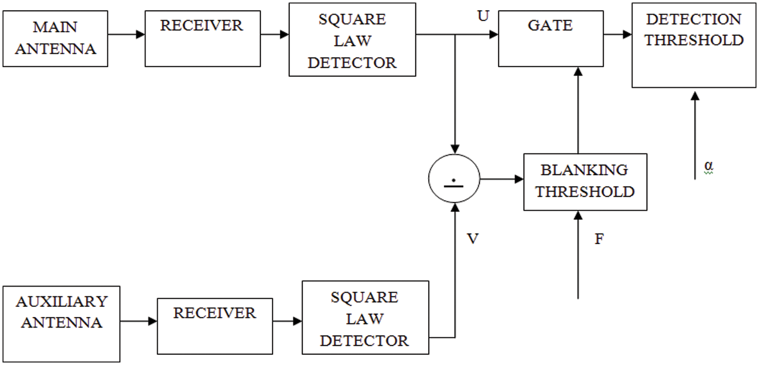
Figure 4: Block diagram of sidelobe blanking
In this, the output pairs (U, V) can be viewed as points in the U-V plane. Maisel logic divides the (U, V) quarter plane into three regions, namely: blanking region (B1), detection region (D), and null region (N), shown in Fig. 5. These regions are defined as
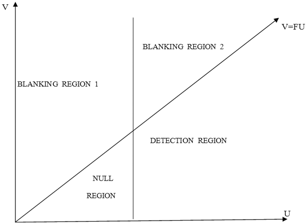
Figure 5: Region of operation in SLB
SLB is designed with three theories in mind.
1. The Null Hypothesis (H0) states that both channels are noise-free.
2. Hypotheses (H1) are on target in the major lobe.
3. In the main lobe, hypotheses (H2) in the same range cell as the target or interference signal in the sidelobe area.
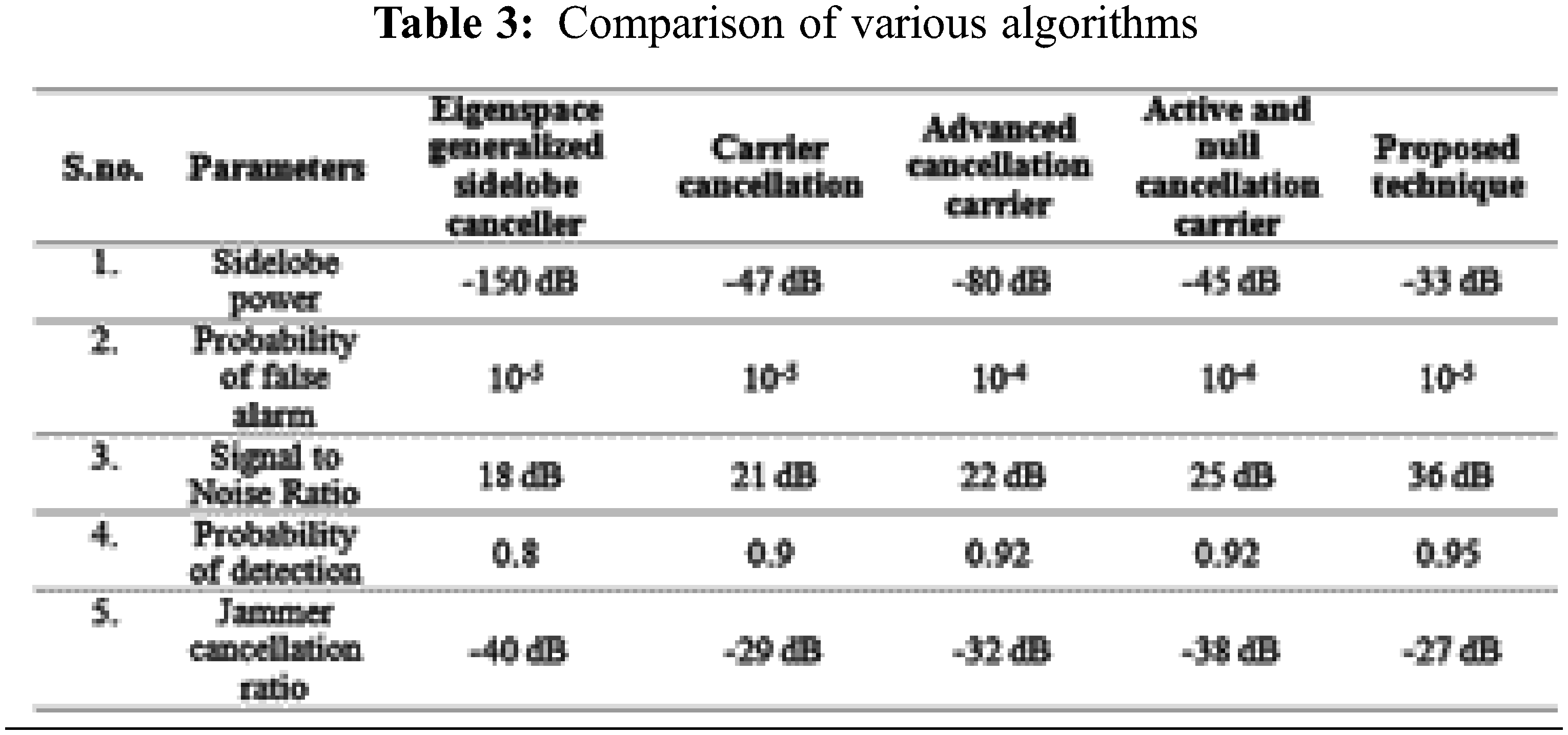
Constant false alarm rate (CFAR) is an ECCM method made important to keep the objective from being over-burdened by false alarms, which diminishes the ability of radar to recognize wanted targets. The acronym CFAR refers to a common type of flexible calculation used in radar frameworks to determine target returns based on noise, mess, and impedance. The CFAR processor modifies the recognition limit as a component of the neighborhood impedance gauge dependent on the plan’s false-alarm likelihood and CFAR calculation shown in Tab. 3. During CFAR activity, where edge setting depends on a specific expected noise level, the superposition of the entirety of this unessential mess on the head of the noise can increase the false alarm rate past adequate cutoff points. Staying away from that by raising the limit may diminish the location likelihood of values falling beneath the indicated levels. CFAR is accomplished to the detriment of the low likelihood of the location of wanted targets. CFAR can likewise create false echoes when there is a non-uniform mess and corrupt the range goal.
The performance of the cell averaging CFAR and that of the ideal fixed limit can be compared in warm noise or uniform mess, but with an associated ‘CFAR tragedy.’ This error is manifested by an increase in the edge-increasing component necessary to achieve a particular false alarm rate over that required if the mean level had been accurately evaluated. It is generally defined as the increase in normal sign-to-noise proportion required to achieve a specific likelihood of detection and false alarm. The cell under test, xi, is shown in the centre of a one-dimensional information vector of range cells in Fig. 4. At the midway of the noise boundary, the information in the dim cells on either side, speaking to information from ranges ever closer to the radar than the cell under test, is arrived. Reference cells are the name given to these phones. The normal is not allowed for the cross-incubated cells swiftly adjacent to the phone under test, known as watch cells. The reason for this is that if an objective is present, it can ride extend cells.
As the sticking signals in yields from both the basic and assistant getting architectures are equal in amplitude but invert in phase, the sticking signs could be removed by combining both yields. The side lobe cancellation framework surpasses the non-sound sidelobe abrogation framework for counter sticking performance. SLC surrenders when there is no receiver noise.
Here S-return echo vector; J-noise power vector; JaT, Ja1, Ja2, …, Jak-Intruder power in the sub-channel antenna; W-Weight.
By default, the SLC framework’s helper channel employs two symmetrical channels. It is shown that the Optimum Weights can be computed using a symmetrical guideline, in which the sign and stickiness of the SLC yield are symmetrical.
The sign and the sticking sign are seen as being unintelligent, and this condition is described as,
The weight that can be acquired from a viable obstacle is
The amount of power is calculated as follows:
The residual jammer power is
As a result of the noise,
where N is the primary channel’s noise vector, Na is the auxiliary channel’s noise vector, P is the signal power, Pj is the jammer power, R is the signal matrix, J is the primary jammer power, and Ja is the auxiliary jammer power. The symmetrical guideline expresses and illustrates the feasible weights as.
The jammer cancellation ratio is calculated by
where
5 Results and Performance Analysis
The experimental results are based on the general SLC shown in Figs. 6 and 7 where ð ð is main radar signal, sap is pth auxiliary antenna signal, α0 is primary reception apparatus target echo signal sufficiency, αp is auxiliary antenna(s) target echo signal amplitude(s), s is target echo signal examples vector, β0, k, βp,k are amplitudes of sticking signs at fundamental and kth assistant radio wires, sjk are sticking sign examples vectors and n0, np are recipients noise signal vectors.
where z is the vector of yield signal instances, Sm is the vector of primary receiving wire signal examples, Sa is the grid of helper radio wires signals, and W is the vector of assistant channel complex loads. Load figuring is the most important activity in sidelobe retraction. The number of these loads is determined by minimizing the residual force shown in Fig. 12.
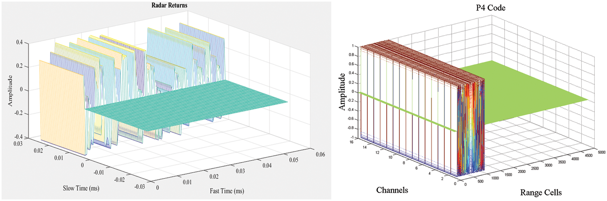
Figure 6: Radar echoes
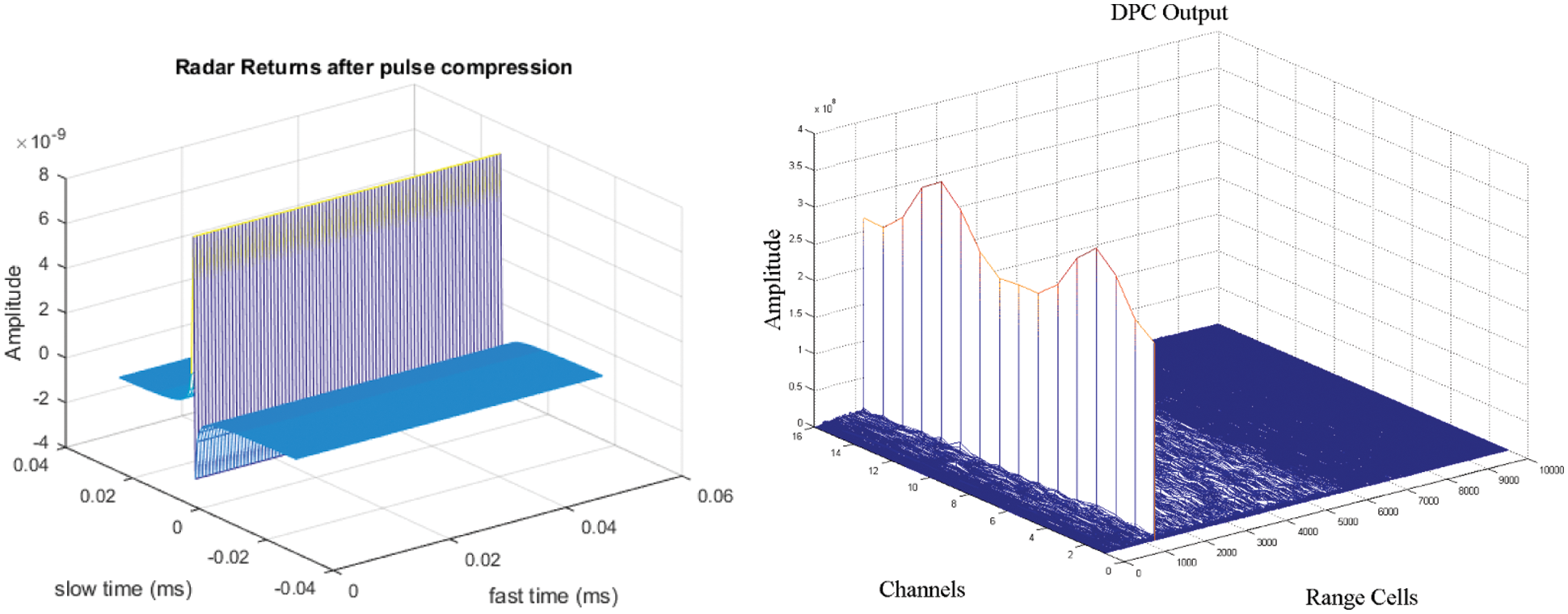
Figure 7: Pulse compressed echoes
The load calculating methodology depicted is based on a covariance lattice assessment. The length of the sign fragment used for covariance lattice calculation is the most important element impacting covariance. Monte Carlo simulation was used to examine the influence of this length. The quantity considered was sidelobe sticking sign concealment as a percentage of the length of the sign example. The concealment of sidelobe sticking signs near foundation noise power was evaluated for various sticking sign to noise foundation proportions, and the findings were compared for all sticking sign to noise foundation proportions.
Since the evaluated and assessed SLC computation [18] relies on the common relationship between the principal and helper channels, the presence of a robust mainlobe signal inside the helper channel reduces productivity substantially, as seen in Fig. 8. When a firm mainlobe signal is present inside the region, sidelobe retraction is compromised. This happens a lot in densely cluttered areas. Considering the genuine record of VHF radar with fixed helper radio wires cluster, the aftereffect of solid ground mess signal is shown in Fig. 6, where mainlobe mess indeed increases noise level by boosting assistance receiving wire signal.
Figure 8: SLC and SLB output
Genuine use of SLC calculations frequently necessitates the creation of additional sticking indicators, as indicated in Fig. 9, at that point number of helper channels. Many assistance channels without remuneration for sticking signs went via principal radio wire sidelobes in this situation, and the remaining sticking force is much more grounded. Consider the collection of two orthonormal sticking signs (symmetry is perfectly feasible for free signals, and irregular plentifulness can be incorporated into amplitude coefficients), where the data transmitted by the primary and one helper radio line is represented by
where s1, s2 are jamming signals, α1, α2 are main channel signal (complex) amplitudes, and β1, β2 are auxiliary channel signals (complex) amplitudes shown in Figs. 10 and 11.
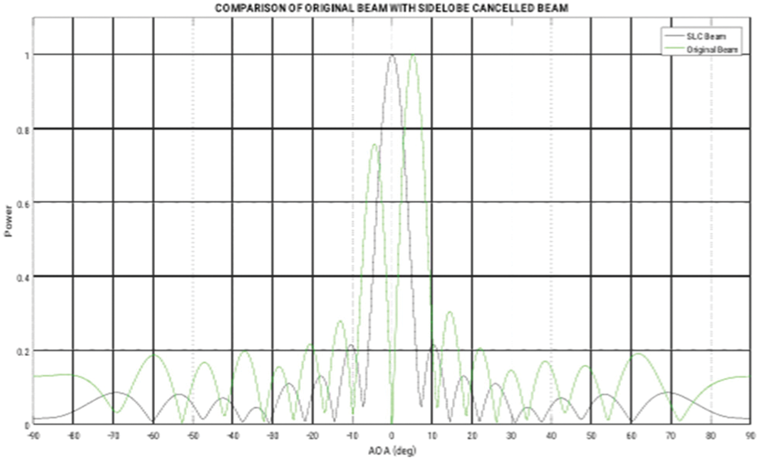
Figure 9: Comparison of SLC and original beam

Figure 10: Beamformer output

Figure 11: Detection Serformance for varying reference channels
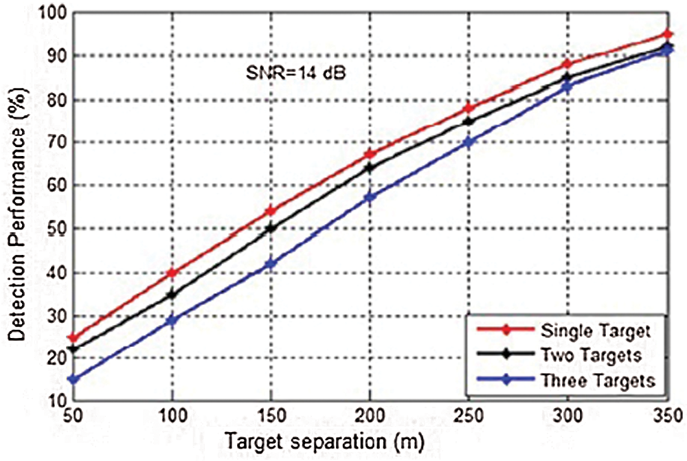
Figure 12: Detection performance for different range resolutions with signal to noise ratio 14 dB
The research presented in the journal explains how to reproduce sidelobe wiping out the execution using single and multiple gatekeeper radio lines. In terms of assistance radio wire covariance lattice, basic and helper radio wire connection vector, and weight framework for single and multiple jammers, a general articulation of framework execution has been achieved. A more thorough analysis of a variety of auxiliary reception devices and jammers is conducted to properly plan the canceller in terms of the sticking condition. Analytically, the yield SNR or information sticking proportions can be utilized to assess the test’s detection performance. The hypothetical fake warning likelihood, as well as the calculation’s limits N and K, define the detection limit. The proposed approach enhances the detection performance of weak targets as well as the post-processing SNR. The simulation results demonstrate that the SNR of several reference channels has improved significantly. The probability of false alarms is reduced when target detection is based on sidelobe cancellation and sidelobe blanking. In the trade-off between detection probability and total number of false alarms, the total number of false alarms rapidly grows.
Funding Statement: The authors received no specific funding for this study.
Conflicts of Interest: The authors declared that they have no conflicts of interest to report regarding the present study.
1. P. Alinezhad and R. S. Saeid, “Broadband adaptive beamforming of conformal arrays for wireless communications based on generalized sidelobe canceller,” Wireless Personal Communications, vol. 96, no. 1, pp. 1131–1143, 2017. [Google Scholar]
2. X. Ma, L. Le, S. Weixing, H. Yubing and Z. Renli, “Adaptive interference nulling with pattern maintaining under mainlobe subspace and quadratic constraints,” IET Microwaves, Antennas & Propagation, vol. 12, no. 1, pp. 40–48, 2018. [Google Scholar]
3. H. Bui-Van, H. Valentin, C. Christoph, G. François and E. de Lera Acedo, “Direct deterministic nulling techniques for large random arrays including mutual coupling,” IEEE Transactions on Antennas and Propagation, vol. 66, no. 11, pp. 5869–5878, 2018. [Google Scholar]
4. H. Bui-Van, A. Jens, A. Michel, G. Quentin, R. Christopher et al., “Fast and accurate simulation technique for large irregular arrays,” IEEE Transactions on Antennas and Propagation, vol. 66, no. 4, pp. 1805–1817, 2018. [Google Scholar]
5. D. Paulraj and N. Subramani, “A gradient boosted decision tree-based sentiment classification of twitter data,” International Journal of Wavelets, Multiresolution and Information Processing, World Scientific, vol. 18, no. 4, pp. 1–21, 2020. [Google Scholar]
6. C. P. D. Cyril, J. R. Beulah, N. Subramani, P. Mohan, A. Harshavardhanet al., “An automated learning model for sentiment analysis and data classification Of twitter data using balanced CA‐SVM,” Concurrent Engineering Research & Application, vol. 29, no. 4, pp. 386–395, 2021. [Google Scholar]
7. S. Neelakandan and A. Ramanathan, “Social media network owings to disruptions for effective learning,” Procedia Computer Science, vol. 172, no. 5, pp. 145–151, 2020. [Google Scholar]
8. S. Divyabharathi and S. Rahini, “Large scale optimization to minimize network traffic using MapReduce in big data applications,” in Int. Conf. on Computation of Power, Energy Information and Communication (ICCPEIC), India, pp. 193–199, 2016. [Google Scholar]
9. N. Subramani and J. Gokul Anand, “Trust based optimal routing in MANET's,” in 2011 Int. Conf. on Emerging Trends in Electrical and Computer Technology, Nagercoil, pp. 1150–1156, 2011. [Google Scholar]
10. J. De Witt, M. Alahmadi and A. Alzamil, “Design and use of a mobile x-band high range resolution radar research facility,” in IET Int. Conf. on Radar Systems, Glasgow, UK, pp. 1–6, 2018. [Google Scholar]
11. R. Chithambaramani and S. Angel Latha Mary, “Determining the shortest current flow path using Dijkstra’s algorithm in mess circuit,” International Journal of Innovative Technology and Exploring Engineering, vol. 8, no. 8, pp. 348–352, 2019. [Google Scholar]
12. M. Sun, W. Yide, B. Cédric Le, P. Jingjing and D. Yuehua, “Signal subspace smoothing technique for time delay estimation using music algorithm,” Sensors, vol. 17, no. 12, pp. 1–12, 2017. [Google Scholar]
13. B. Chen, C. Baoxin, G. Jian, H. Yong and H. You, “Space-range-doppler focus-based low-observable moving target detection using frequency diverse array mimo radar,” IEEE Access, vol. 6, no. 2, pp. 43892–43904, 2018. [Google Scholar]
14. S. Satpathy, S. Debbarma, S. C. Sengupta Aditya and K. D. Bhattacaryya Bidyut, “Design a fpga, fuzzy based, insolent method for prediction of multi-diseases in rural area,” Journal of Intelligent & Fuzzy Systems, vol. 37, no. 5, pp. 7039–7046, 2019. [Google Scholar]
15. C. Ramalingam and M. Prakash, “An efficient applications cloud interoperability framework using i-anfis,” Symmetry, vol. 13, no. 2, pp. 1–12, 2021. [Google Scholar]
16. R. Chithambaramani and P. Mohan, “Addressing semantics standards for cloud portability and interoperability in multi cloud environment,” Symmetry, vol. 13, no. 2, pp. 1–18, 2021. [Google Scholar]
17. M. Sundaram, S. Satpathy and D. Sanchali, “An efficient technique for cloud storage using secured de-duplication algorithm,” Journal of Intelligent & Fuzzy Systems, vol. 42, no. 2, pp. 2969–2980, 2021. [Google Scholar]
18. P. V. Rajaram and P. Mohan, “Intelligent deep learning based bidirectional long short term memory model for automated reply of e-mail client prototype,” Pattern Recognition Letters, vol. 152, no. 12, pp. 340–347, 2021. [Google Scholar]
 | This work is licensed under a Creative Commons Attribution 4.0 International License, which permits unrestricted use, distribution, and reproduction in any medium, provided the original work is properly cited. |