DOI:10.32604/iasc.2023.027563
| Intelligent Automation & Soft Computing DOI:10.32604/iasc.2023.027563 | |
| Article |
Data Aggregation-based Transmission Method in Ultra-Dense Wireless Networks
Department of Computer Software Engineering, Soonchunhyang University, Asan, 31538, Korea
*Corresponding Author: Seokhoon Kim. Email: seokhoon@sch.ac.kr
Received: 20 January 2022; Accepted: 13 March 2022
Abstract: As the Internet of Things (IoT) advances, machine-type devices are densely deployed and massive networks such as ultra-dense networks (UDNs) are formed. Various devices attend to the network to transmit data using machine-type communication (MTC), whereby numerous, various are generated. MTC devices generally have resource constraints and use wireless communication. In this kind of network, data aggregation is a key function to provide transmission efficiency. It can reduce the number of transmitted data in the network, and this leads to energy saving and reducing transmission delays. In order to effectively operate data aggregation in UDNs, it is important to select an aggregation point well. The total number of transmitted data may vary, depending on the aggregation point to which the data are delivered. Therefore, in this paper, we propose a novel data aggregation scheme to select the appropriate aggregation point and describe the data transmission method applying the proposed aggregation scheme. In addition, we evaluate the proposed scheme with extensive computer simulations. Better performances in the proposed scheme are achieved compared to the conventional approach.
Keywords: Data aggregation; data transmission; ultra-dense network; machine-type communication; Internet of Things
Recently, the Internet of Things (IoT) has been rapidly growing with diversity in terms of devices, data and communication technologies. In fifth generation (5G) cellular systems, machine-type communication (MTC) devices as IoT devices have hyper-connectivity and provides various network services using produced data [1–6]. IoT devices connect to a cloud platform such as AWS or Google cloud through networks. The cloud platform processes produced data from the networks and supports various intelligent services. The data produced by the MTC devices have different characteristics and heterogeneity according to their target services. Furthermore, MTC devices allow various communication technologies such as low power wide area communication (LPWA), long term evolution for machines (LTE-M), narrowband IoT (NB-IoT), 5G Massive IoT etc. The MTC uses a narrow band communication technology with a low data rate and allows numerous devices to connect to a communication network. This kind of communication builds an ultra-dense network (UDN). The MTC services in UDNs collect data from MTC devices in a wide area and provide intelligence by analyzing the collected data. This is the major service type in smart city, smart factory and smart IoT applications [7].
The data generated by a UDN continue to increase explosively and is transmitted from the radio access network to the core network via uplink communication. In addition, the MTC data are generated periodically, but when an event occurs, the data are generated with burst characteristics. Therefore, data transmission in UDNs puts a strain on the radio access network and the core network of application services. If the unique traffic characteristics of UDNs are considered in the same manner as the conventional network systems (i.e., human-to-human network system), service efficiency may be decreased. Before IoT services are advanced, network services in UDNs were focused on the human-to-human communication and MTC was not considered [8]. Numerous devices now attend to the network for their services and are configured with UDNs. MTC has thus become even more important.
UDNs consist of an edge network. MTC devices in the radio access area connect to a gateway integrated with a base station. Data from the MTC devices are delivered to the edge cloud via the gateway. The edge cloud processes the received data and uses it for service control and application. As the massive MTC devices in UDNs attend to data transmission, the entire network services are affected. The uplink traffic of MTC devices is concentrated on several gateways as the bottleneck point to access the Internet cloud. Many signals of MTC devices are created. Congestion can be caused in the uplink data transmission of UDNs, and thus the efficiency of conventional network services in human-to-human communication can be decreased. To improve IoT service efficiency, it is necessary to apply data aggregation when massive MTC traffic is transmitted. Data aggregation combines data of the same type. Thus, the amounts of traffic to deliver to the central cloud are be reduced. Traffic congestion in UDNs can be relieved. There are several data aggregation architectures according to the function of the aggregator [8–15]. To combine data, one or more fixed aggregators can be used; one or more user equipment items, such as mobile aggregators can also be used. In addition, fixed and mobile aggregators can be used together. The aggregators combine MTC traffic and transmit to the central cloud. Fig. 1 shows the aggregation architecture in UDNs.
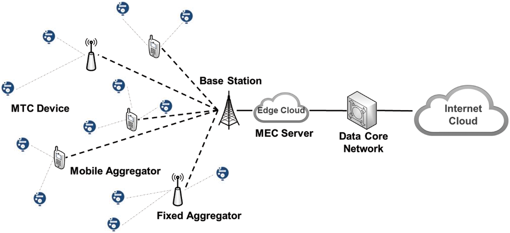
Figure 1: Ultra dense network (UDN) architecture
When the MTC devices attempt to transmit data, they choose aggregators for data aggregation. In general, they send data to the nearest aggregators or to the aggregators selected by probability. In the UDN, various types of data are created from MTC devices and aggregators just gathers several types of data among them. As mentioned earlier, data of the same type are combined in the aggregator, but data of different types are appended to the existing data record. When data are combined, their sizes can be reduced. When data are appended, their sizes are increased. Thus, if an appropriate aggregator is not selected for data transmission, the traffic amount in the UDN can be increased. In this paper, we propose a data transmission method in UDNs to improve the aggregation efficiency. In the proposed method, each MTC device obtains service type information from aggregators. The service type information refers to the type of data collected by the aggregator. Because the MTC device also generates several types of data, an aggregator with many matching data types is selected. Therefore, the aggregation efficiency can be improved by increasing the number of data to be combined rather than appended.
The remainder of this paper is organized as follows. Section 2 discusses conventional aggregation methods as the related work. In Section 3, we explain the proposed aggregation-based data transmission method. The performance evaluation and results are described in Section 4. Finally, we conclude the paper in Section 5.
Massive MTC devices consist of the UDN. One of the major issues in UDNs is the congestion of uplink traffic. As mentioned in the previous section, burst traffic generation over the air can affect service efficiency. Thus, it is necessary to reduce the amount of uplink traffic. Data aggregation is the solution for massive access in UDNs. Data aggregation is performed in aggregation points. In general, gateways or base stations can be a fixed aggregator. Mobile devices such as a smart phone can be a mobile aggregator. The aggregators collect data from other IoT devices and transmit the combined data to central cloud [16]. The data aggregation method is classified by the aggregator’s characteristics, whether it be a dedicated fixed aggregator, mobile aggregator, or a combination of fixed and mobile aggregators [1]. Using a dedicated fixed aggregator as a base station can easily determine the aggregation point. MTC devices with uplink data traffic select the closest dedicated gateway and transmit data traffic [9]. When the MTC device uses multiple dedicated aggregators, it is necessary to exchange location information to avoid duplicated transmissions. Depending on the location information, the MTC device selects aggregators in the nearby area [10]. When a smart phone, which has the mobility characteristic, is employed, a mobile aggregator can be used. Thus, it moves to the IoT area and relays data from MTC devices [11]. In the single mobile aggregator, data traffic can be concentrated on the aggregator. This leads to increasing transmission delays. Thus, a set of multiple mobile aggregators can be employed. If data transmission is distributed, transmission delays can be reduced [14]. However, in MTC applications, the set of multiple mobile aggregators is mainly used to extend the data transmission range [12]. To enhance the MTC network capability, one study proposed a cooperative data aggregation that combines the fixed aggregators and the mobile aggregators [13]. In the above data aggregation methods, IoT devices select the closest aggregator to transmit data.
The selection of the aggregator has been taken seriously in wireless sensor networks (WSNs). A WSN is a network composed of tiny devices called sensor nodes. The aggregator selection is handled in the hierarchical routing of WSNs [17]. Hierarchical WSNs construct several clusters and a cluster-head in each cluster aggregate’s data from other nodes. The WSN aggregators are selected using a method to maximize the network lifetime. In other words, load balancing for energy consumption in the WSN is important. Therefore, a cluster-head (i.e., aggregator) selection based on probability or residual energy was proposed. Because the WSN considers just one type of data transmission, the aggregator selection of WSNs cannot be applied to UDN services. UDN devices have a longer transmission range and greater density than WSN nodes. They can easily find aggregators. In addition, heterogeneous data are generated from devices in the UDN. Such data should be transmitted efficiently. For transmission efficiency, it is necessary to select an aggregator in consideration of the type of UDN data.
3 Proposed Approach for Data Transmission
As shown in Fig. 1, a UDN consists of aggregators and MTC devices. Data of the MTC devices are transmitted to aggregators and data of the same type are combined. As the number of devices being aggregated increases in the network, the number of data incoming to the core network from the radio access network can be reduced, and congestion around the base station can be avoided. The number of MTC devices being aggregated is represented in Eq. (1).
where NT is the number of total MTC devices in the UDN and MT is the number of aggregators. xk is the key type of the generated data in the device x which is not included in an aggregator, and Sj is a set of data keys in the aggregator j. D is a set of devices selected their aggregator. Then, by the indicator function (1{·}), the number of devices (n) being aggregated can be obtained. That is, in the UDN, among devices that did not select an aggregator, if the key type of the data generated by the device is included in the set of data keys handled by the aggregator, the device selects the aggregator and transmits its data. Then, the aggregator combines data from the devices and delivers to a base station.
The combined data in the aggregator are composed of key and value pairs such as JSON [18] format. Thus, data with the same key are combined with other values, and if the key is different, the key-value pair is appended to the existing data. To increase the aggregation efficiency, MTC devices should transmit data to the aggregator that has the same key type as the generated data. The number of data keys of whole aggregators in the UDN is represented in Eq. (2).
where f(·) obtains the number of data keys from Sj. Data transmitted from the aggregators to the base station are represented in Eq. (3), which is expressed as multiplying the unit size of the data with the number of data keys.
For the data with different keys, the aggregation is not performed. Such data are transmitted to the base station by additional transmission or piggybacking on the existing data. Eq. (4) represents the size of non-aggregated data.
The transmitted data size from the aggregators to the base station becomes the sum of Eqs. (3) and (4). The size of the aggregated data is not related to the number of devices being aggregated but the size of non-aggregated data depends on the number of devices being aggregated. Therefore, if the number of devices being aggregated is increased, the size of non-aggregated data is decreased. This leads to less energy consumption and congestion avoidance around the base station. For the efficiency of the UDN generated heterogeneous data, it is necessary to maximize data aggregation in the aggregators.
3.2 Aggregation-based Data Transmission
To combine data with the same data keys, aggregators periodically broadcast a data-key flag message. The MTC device that receives the data-key flag message compares the keys in the message with its generated data types. Because the network elements are densely deployed in the UDN, the MTC device can receive the data-key flag messages from multiple aggregators. For uplink data transmission, the MTC device should select a proper aggregator. The aggregator selection is affected on the uplink data transmission path. If the aggregator receives MTC data of its own data type, it can perform an aggregation operation. However, if the aggregator receives other types of data, it must append the other types of data to the existing data set. This results in a larger number of data to be transferred from the aggregator to the data core network.
To represent data-key flags, a several-bytes message can be employed. If the message uses one byte, a maximum of 8 data-keys can be represented. The MTC devices make their own data-key flags within the single byte. Each MTC device compares its own data-key flag with the broadcasted messages from aggregators. Through AND logical operation, the MTC device obtains the data-key counts of neighbor aggregators and the largest data-key count becomes the major element to select an aggregator for uplink data transmission. Then, the number of data combined in the UDN aggregators increases, while the number of data transmitted from the aggregator to the base station is reduced. Fig. 2 shows that the MTC device compares its own data-key flag with the aggregator’s data-key flag.
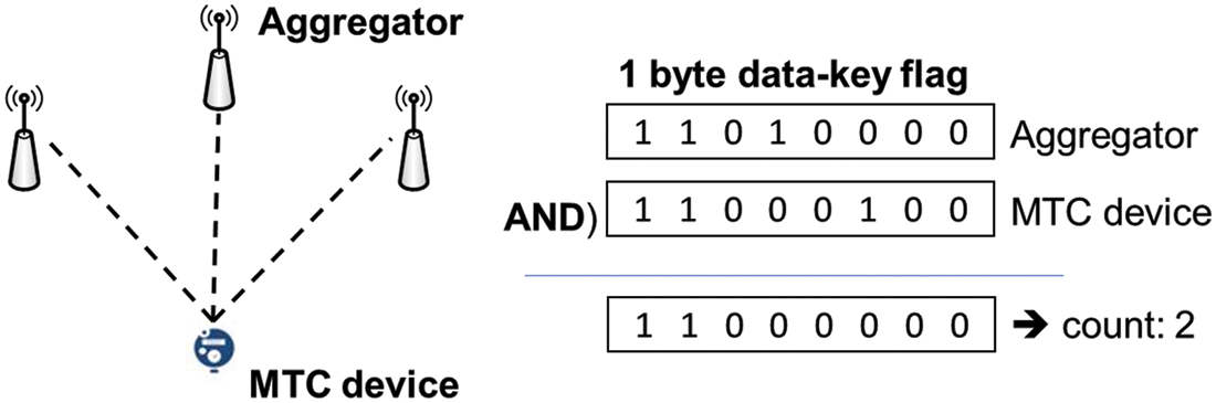
Figure 2: Data-key flag comparison in the MTC device
For efficient uplink data transmission, the MTC device should consider several elements such as hops in the radio access network, traffic loads, and the data-key count in the relay node (i.e., the aggregator). The uplink transmission efficiency (eff) in the UDN is defined in Eq. (5).
where Ckey is the data-key count representing the number of data types that can be aggregated. Ltf is the traffic load in the aggregator, which can be modeled as throughput (ρ) by incoming rate (λ) and outgoing rate (μ), as is represented in Eq. (6).
The transmission efficiency increases as the Ckey is large and the Ltf is low. If the transmission efficiency is considered at the same number of hops, the transmission efficiency is determined by the Ckey and the Ltf (or ρ). Then, the MTC device can select the next hop by using the transmission efficiency as the routing metric. Eq. (7) represents the routing metric.
where K is a constant that compensates for the metric value. This routing metric can lead to maximizing aggregation effect in the UDN, and thus it can reduce the amount of traffic that has to be transmitted in the network. Fig. 3 represents the next-hop selection algorithm using the routing metric in Eq. (7).
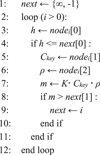
Figure 3: The next hop selection algorithm using the transmission efficiency in the UDN
The MTC device computes the routing metric for the aggregator i. next is a data structure to choose an aggregator as the next hop and consists of hops in the radio access network and the routing metric. It is initialized to ∞ as hop count and −1 as the metric value (line 1). nodei is a data structure for routing information of the aggregator i. It is composed of hops in the radio access network, data-key counts and throughput as the routing metric. When the hop-count in the nodei data structure is less than or equal to the next data structure, the MTC device computes the routing metric m using the routing information (line 4~7). If this routing metric is greater than the next data structure, the aggregator is selected for the MTC device (line 8~9). The selected aggregator combines and relays devices’ data until the point at which there are many data types to be combined and the traffic load is relatively small.
The performance is evaluated by extensive computer simulations. The simulation codes are implemented by SMPL library [19], which is based on C language and provides event-driven programming environments. The network architecture for the simulation is configured as shown in Fig. 1. MTC devices are deployed in the UDN area and connected to several aggregators. Aggregators are connected to the core network and relay data traffic from MTC devices to an application server. In this network architecture, the proposed method is compared to a conventional aggregation method. In general, in the conventional method, the device chooses the aggregator with the lowest cost (i.e., short distance, strong signal strength, high bandwidth, etc.). However, in UDNs with multiple aggregators, the cost metric can be very similar. The aggregator selection then becomes similar to random selection. Thus, we assume that the conventional method utilizes a random aggregator selection. The proposed method works on the algorithm in Section 3.2, and the performance is evaluated in the simulation environments in Section 4.1.
The computer simulation is operated according to the state machine in Fig. 4. The INIT state initializes the system parameters for the simulation. The TIMER state checks events per every unit time. This unit time is set to 10 mses. The XCAST state and TF_GEN state are invoked when the TIMER state is started. The TF_GEN state generates data traffic in the MTC devices. The data traffic generation has exponential distribution [20,21] with 60 sec as the mean value. Data generated by each MTC device has data types randomly selected among 8 data types. The number of data types is randomly determined from 1 to 3. The XCAST state broadcasts data-key flag information at the aggregators. This broadcast interval is 60 sec. The data-key flag in each aggregator is also randomly determined from 1 to 5. When data packets are generated, MTC devices determine their next hop and send the packets in the SEND state, and check successful transmission in the RECV state. Through the SEND and RECV states, the MTC devices transmit data traffic to aggregators and the transmission delay is assumed to 10 msec. When the aggregators are ready to transmit aggregated data, they can send data packets in the AP_SEND state and check the successful transmission in AP_RECV state. The transmission delay at aggregators is assumed to 50 msec.
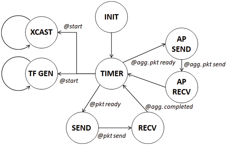
Figure 4: State diagram of the computer simulation
The aggregators connect to the core network via base stations. Thus, the transmission delay at the aggregators is longer than that of the MTC devices. In addition, the communication link has 5% link error in both the MTC devices and aggregators communication. If transmission failure occurs, two retries are allowed. In the simulation, 50 MTC devices are deployed and they have 3 aggregators. The simulation time is set to 24 h. To measure the energy consumption at the aggregators during data transmission, the energy consumption model in [22] is exploited.
As shown in Eq. (8), the consumed energy in the network is measured by dividing the amount of energy required for data to be transmitted by the transmission period. The amount of energy required for data to be transmitted is determined by the number of bytes and packets of the transmitted data [22].
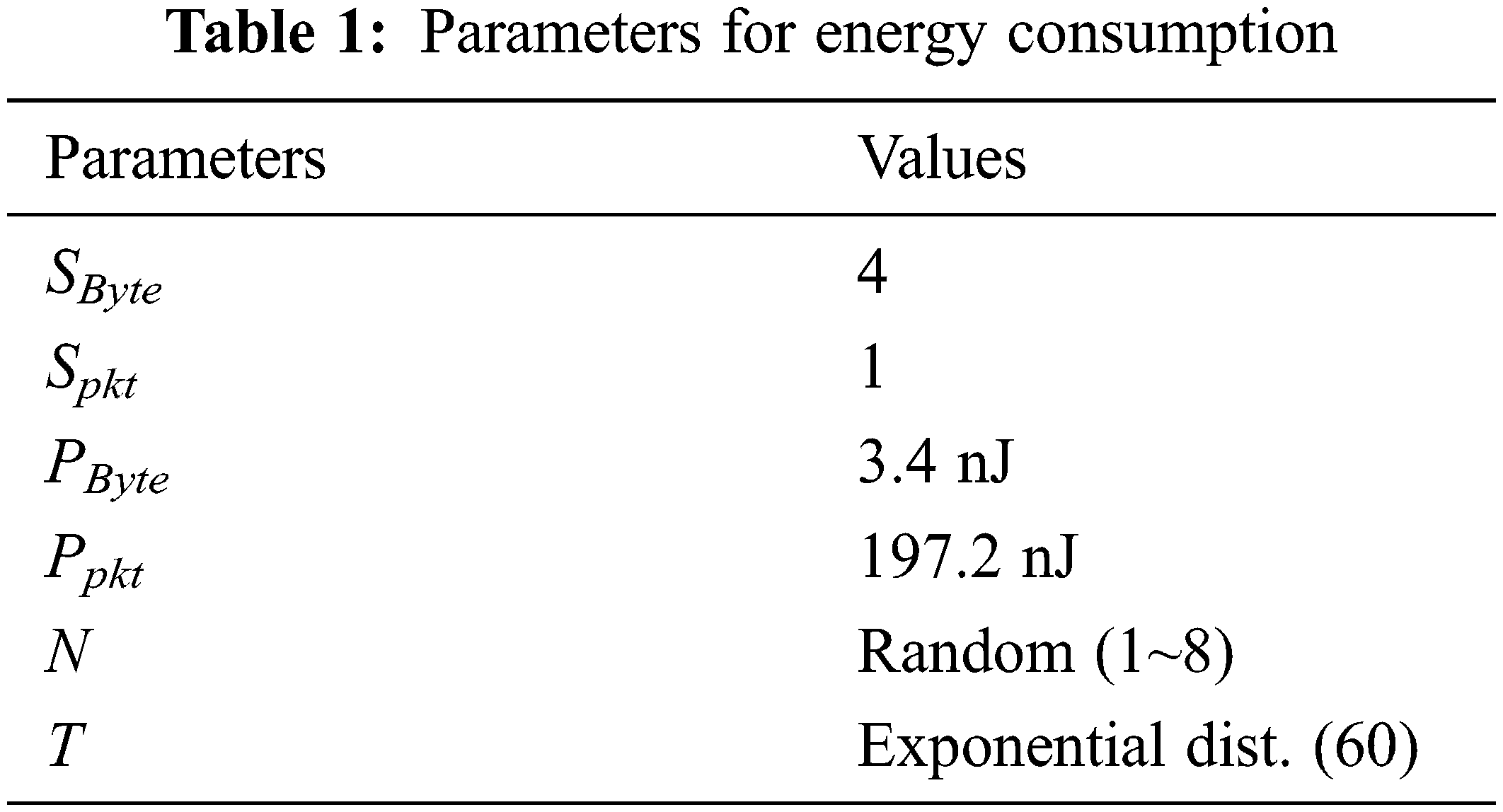
where Sbyte and Spkt are the number of bytes and packets. Pbyte is the energy consumed to transmit a single byte. Ppkt is the energy consumed to transmit a single packet. N is the number of aggregated data types in the aggregator. T is the transmission interval. Through this energy model, the energy consumption in the aggregators can be measured. In the aggregator, the received data are combined and transmitted to a base station in a single packet. When the aggregation is performed, each data type is concatenated into 4 bytes. Pbyte and Ppkt are set to the value of [22,23]. Then, the parameters for energy consumption in the simulation are given in Tab. 1.
As mentioned earlier, data aggregation in UDNs is very effective. The proposed method is compared to the conventional method. The propose method considers key types of data for aggregation, however the conventional method selects aggregators using a distance between a device and an aggregator. If the key type of data is not taken into account, the efficiency of the aggregator cannot be improved. The proposed method provides a way for MTC devices to select an aggregator to maximize the effect of data aggregation. Fig. 5 represents the number of transmitted data in the aggregators. In both the conventional and the proposed methods, the number of transmitted data from MTC devices is the same. However, the number of transmitted data from aggregators can be different according to data aggregation performance. As shown in Fig. 5, the proposed method can reduce the number of transmitted data in the aggregators (Conventional: 39,572; Proposed: 29,995). The reason is that MTC devices in the proposed method transmit data to an aggregator with a high aggregation rate using the data-key flag. This causes the low transmission delays.
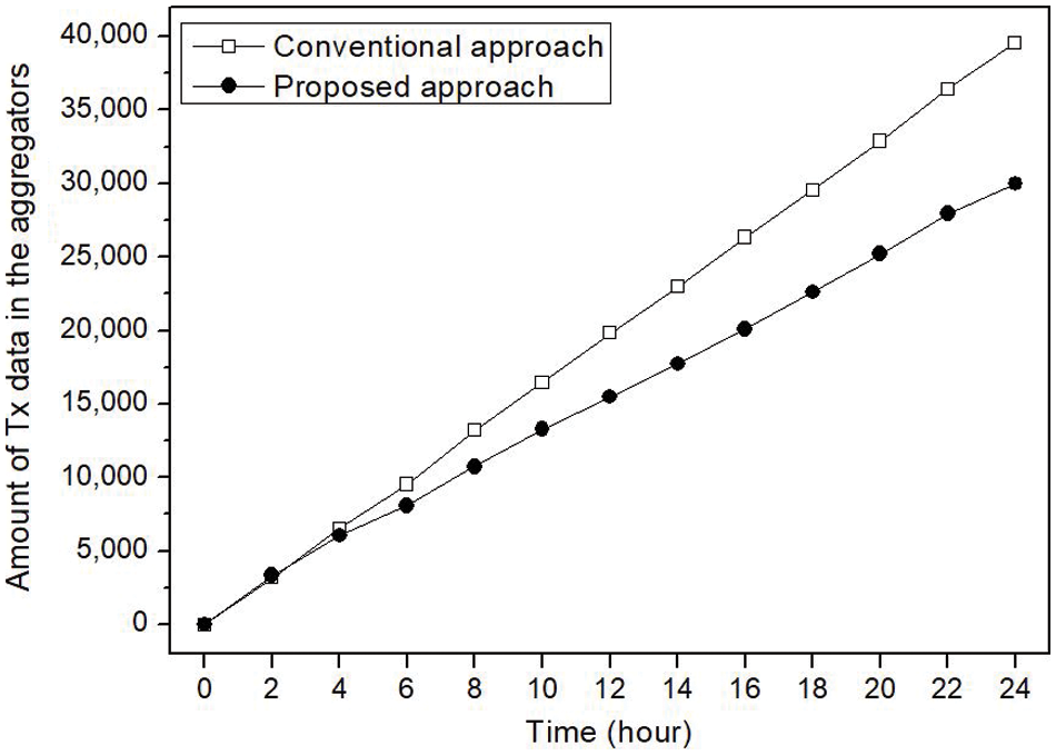
Figure 5: Number of transmitted data in the aggregators
Fig. 6 shows the average number of data types in the aggregators. In the conventional method, whole aggregators use maximum piggybacking for data types. However, the proposed method does not use maximum piggybacking for data types. The aggregator attempts piggybacking if the data type is not the same as the data-key flag. Thus, in the proposed method, by referring to the data-key flag of the aggregator, the aggregation rate is increased by selecting an aggregator that has high consistency with the type of data generated by the MTC device. Because of this high aggregation rate, the proposed method can reduce the number of transmitted data in the aggregators as shown in Fig. 5.
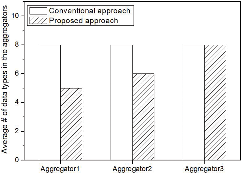
Figure 6: Average number of data types in the aggregators
Fig. 7 represents consumed energy in the aggregators during data transmission. As shown in the UDN architecture of Fig. 1, the aggregator is a device using wireless communication to support services for MTC devices. Therefore, energy consumption is very important. Although there is no significant difference in energy consumption over the course of 12 h, there is a significant difference in energy consumption thereafter (Conventional: 1844.581; Proposed: 1311.997). In the simulation, energy consumption was compared for 24 h, but considering that the MTC device needs to operate for hundreds of hours, the proposed method can significantly reduce energy consumption. That is, energy consumption in the network can be greatly reduced through data aggregation. This can extend the lives of devices on the network.
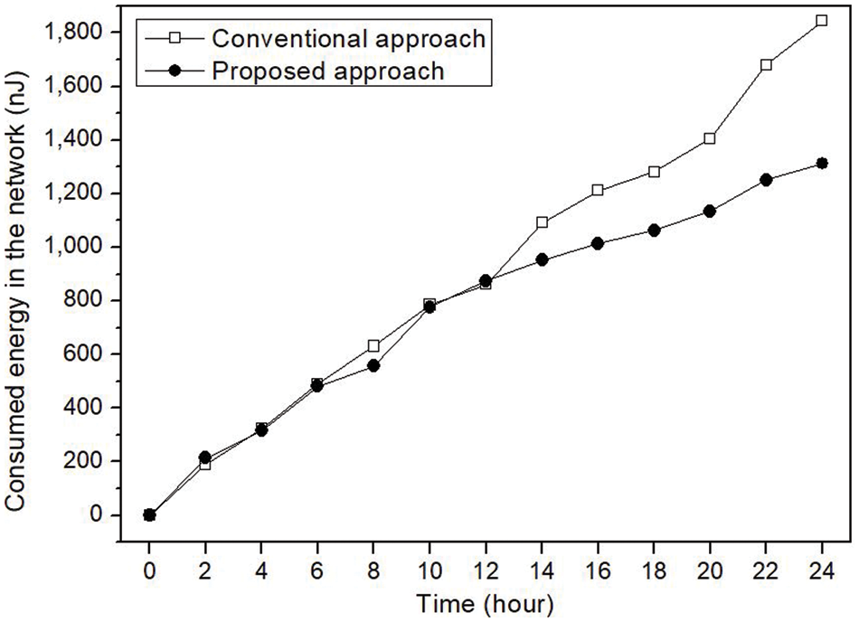
Figure 7: Consumed energy in the aggregators during data transmissions
For various IoT services, many MTC devices are densely deployed in order to construct a UDN. Data traffic in the UDN is generated by MTC devices and delivered to application servers via uplink communication. Data aggregation is applied to improve the efficiency of uplink data transmission. In this paper, unlike the conventional method, the MTC devices select an aggregator considering the data types handled by the aggregator. Thus, aggregators combine more data traffic and thereby increase the aggregation rate, which leads to greater transmission efficiency in UDNs. As shown in Section 4.2, in the proposed method, the aggregators reduced the number of data from the MTC devices by 24%. This resulted in a reduction of the energy consumption of the aggregators by about 29%. In UDNs that generate massive data traffic, the data transmission efficiency could be greatly improved by applying efficient data aggregation. The proposed method reduced the number of data transmissions and the energy consumption using the efficient data aggregation. Accordingly, the proposed method is suitable for massive IoT services and can be effectively used in UDNs for various IoT services.
Funding Statement: This work was supported by the National Research Foundation of Korea (NRF) grant funded by the Korea Government (MSIT) (No. 2021R1C1C1013133), and this work was supported by the Soonchunhyang University Research Fund (No. 20210442).
Conflicts of Interest: The authors declare that we have no conflicts of interest to report regarding the present study.
1. T. Salam, W. U. Rehman and X. Tao, “Data aggregation in massive machine type communication: Challenges and solutions,” IEEE Access, vol. 7, pp. 41921–41946, 2019. [Google Scholar]
2. P. Tam, S. Math and S. Kim, “Intelligent massive traffic handling scheme in 5G bottleneck backhaul networks,” KSII Transactions on Internet and Information Systems, vol. 15, no. 3, pp. 874–890, 2021. [Google Scholar]
3. A. K. Yerrapragada and B. Kelley, “An IoT self organizing network for 5G dense network interference alignment,” in Proc. IEEE System of Systems Engineering Conf., Waikoloa, HI, USA, 2017. [Google Scholar]
4. A. A. Ateya, A. D. Algarni, M. Hamdi, A. Koucheryavy and N. F. Soliman, “Enabling heterogeneous IoT networks over 5G networks with ultra-dense deployment—using MEC/SDN,” Electronics, vol. 10, no. 8, pp. 910, 2021. [Google Scholar]
5. M. A. Adedoyin and O. E. Falowo, “Combination of ultra-dense networks and other 5G enabling technologies: A survey,” IEEE Access, vol. 8, pp. 22893–22932, 2020. [Google Scholar]
6. W. Yang, X. Jing, H. Huang, C. Zhu, Q. Jiang et al., “An efficient markov chain based channel model for 6G enabled massive internet of things,” KSII Transactions on Internet and Information Systems, vol. 15, no. 11, pp. 4203–4223, 2021. [Google Scholar]
7. G. Chopra, R. K. Jha and S. Jain, “A survey on ultra-dense network and emerging technologies: Security challenges and possible solutions,” Journal of Network and Computer Applications, vol. 95, no. 1, pp. 54–78, 2017. [Google Scholar]
8. S. Chen, R. Ma, H.-H. Chen, H. Zhang, W. Meng et al., “Machine-to-machine communications in ultra-dense networks—a survey,” IEEE Communications Surveys & Tutorials, vol. 19, no. 3, pp. 1478–1503, 2017. [Google Scholar]
9. D. Malak, H. S. Dhillon and J. G. Andrews, “Optimizing data aggregation for uplink machine-to-machine communication networks,” IEEE Transactions on Communications, vol. 64, no. 3, pp. 1274–1290, 2016. [Google Scholar]
10. U. Tefek and T. J. Lim, “Relaying and radio resource partitioning for machine-type communications in cellular networks,” IEEE Transactions on Wireless Communications, vol. 16, no. 2, pp. 1344–1356, 2017. [Google Scholar]
11. G. Rigazzi, N. K. Pratas, P. Popovski and R. Fantacci, “Aggregation and trunking of M2M traffic via D2D connections,” in Proc. IEEE Int. Conf. on Communications, London, UK, 2015. [Google Scholar]
12. S. N. Swain, R. Thakur and S. R. M. Chebiyyam, “Coverage and rate analysis for facilitating machine-to-machine communication in LTE-A networks using device-to-device communication,” IEEE Transactions on Mobile Computing, vol. 16, no. 11, pp. 3014–3027, 2017. [Google Scholar]
13. J. W. Raymond, T. O. Olwal and A. M. Kurien, “Cooperative communications in machine to machine (M2MSolutions, challenges and future work,” IEEE Access, vol. 6, pp. 9750–9766, 2018. [Google Scholar]
14. T. Salam, W. U. Rehman, X. Tao, Y. Chen and P. Zhang, “A trust framework based smart aggregation for machine type communication,” Science China Information Sciences, vol. 60, no. 100306, pp. 11, 2017. [Google Scholar]
15. K. R. Remesh Babu, K. G. Preetha, S. Saritha and K. R. Rinil, “An energy efficient intelligent method for sensor node selection to improve the data reliability in internet of things networks,” KSII Transactions on Internet and Information Systems, vol. 15, no. 9, pp. 3151–3168, 2021. [Google Scholar]
16. ETSI, “Machine-to-machine communications (M2MFunctional architecture,” Technical Specification (TS) 102 690 document, v2.0.6, 2013. [Online]. Available: https://www.etsi.org. [Google Scholar]
17. S. A. Dehkordi, K. Farajzadeh, J. Rezazadeh, R. Farahbakhsh, K. Sandrasegaran et al., “A survey on data aggregation techniques in IoT sensor networks,” Wireless Networks, vol. 26, no. 2, pp. 1243–1263, 2020. [Google Scholar]
18. T. Bray, “The javascript object notation data interchange format,” Internet Engineering Task Force (IETF) RFC, RFC 7159, pp. 1–16, 2014. [Online]. Available: https://datatracker.ietf.org/doc/html/rfc7159. [Google Scholar]
19. M. H. MacDougall, Simulating Computer Systems, Techniques and Tool. Cambridge, MA, USA: MIT Press, 1987. [Google Scholar]
20. K. S. Trivedi, Probability and Statistics with Reliability, Queueing and Computer Science Applications. New York, USA: John Wiley & Sons, 2002. [Google Scholar]
21. S. M. Ross, Probability Models for Computer Science. Burlington, MA, USA: Harcourt/Academic Press, 2002. [Google Scholar]
22. L. Guegan and A. Orgerie, “Estimating the end-to-end energy consumption of low-bandwidth IoT application for WiFi devices,” in Proc. IEEE Int. Conf. on Cloud Computing Technology and Science, Sydney, Australia, pp. 287–294, 2019. [Google Scholar]
23. B. F. Cornea, A. Orgerie and L. Lefèvre, “Studying the energy consumption of data transfers in clouds,” in The Ecofen Approach, in Proc. IEEE Int. Conf. on Cloud Networking, Luxembourg, Luxemburg, pp. 143–148, 2014. [Google Scholar]
 | This work is licensed under a Creative Commons Attribution 4.0 International License, which permits unrestricted use, distribution, and reproduction in any medium, provided the original work is properly cited. |