DOI:10.32604/iasc.2023.024027
| Intelligent Automation & Soft Computing DOI:10.32604/iasc.2023.024027 | |
| Article |
Integration of Wind and PV Systems Using Genetic-Assisted Artificial Neural Network
Ponjesly College of Engineering, Nagerkovil, Kanyakumari, 629003, India
*Corresponding Author: E. Jessy Mol. Email: jessyjenkins2015@gmail.com
Received: 30 September 2021; Accepted: 29 January 2022
Abstract: The prominence of Renewable Energy Sources (RES) in the process of power generation is exponentially increased in the recent days since these sources assist in minimizing the environmental contamination. A grid-tied DFIG (Doubly Fed Induction Generator) based WECS (Wind Energy Conversion System) is introduced in this work, in which a Landsman converter is implemented to improvise the output voltage of PV without any fluctuations. A novel GA (Genetic Algorithm) assisted ANN (Artificial Neural Network) is employed for tracking the Maximum power from PV. Among the rotor and grid side controllers, the former is implemented by combining the stator flux with d-q reference frame and the latter is realized by the PI controller. The proposed approach delivers better performance in the compensation of real and reactive power along with the DC link voltage control. The controlling mechanism is verified in both MATLAB and experimental bench setupby using an emulated wind turbine for the concurrent control of DC link potential, active and reactive powers.The source current THD is observed as 1.93% and 2.4% for simulation and hardware implementation respectively.
Keywords: Wind energy converter; double fed induction generator; field oriented control; GA-ANN MPPT; DC-link voltage control
The significance of generation using sustainable energy sources is rapidly increased in the current era since the RE sources helps to rectify the global warming problems and to minimize the usage of non-renewable power sources. Among various RE sources, the wind energy is booming as one of the remarkable sources as it owns the financial advantages of producing extremely large scale energy [1]. TheDFIG is mainly used in the wind turbines as it has various advantageous elements like variable speed characteristics, improved quality and high durability. The DFIG has the capability to manage the real and reactive power output. Despite the fact that the real power relies upon the wind energy, it tends to be governed in a transient way by employing the mechanical active vitality. It assits in incorporating the sustainable power source with the grid by using the DFIG as a consolidated framework. Whenever two sustainable power sources produce optimum power by governing the DFIG’s real power, the complete power is controlled to satisfy the requirement of grid. When the voltage is oscillating, the DFIG creates a measure of reactive power for controlling voltage.The advanced attributes of Variable Speed Consistent Frequency (VSCF) based DFIG has taken a significant part in the wind energy research. Thus, it has gained much attention among the researchers [2].
In DFIG, two parallel connected converters give the necessary current polarity in rotor windings. The grid connected converter is normally categorized as Grid Side Converter (GSC) whereas the converter, which is linked with the rotor windings is categorized as Rotor Side Converters (RSC). The principal function of GSC is to constantly retain the DC voltage and to balance the reactive power in the unbalanced situations [3]. The RSC gives the necessary current in rotor winding to create the necessary reactive and real powers at the stator terminal.
The power generation of variable speed Wind Turbines (WT)is comparatively better than the constant speed WT. By using this variable speed WT, the power generation is increased upto 6% to 39% with respect to the site condition and parameter selection [4–6]. Because of having these advantages, it is generally preferred by both the utilities and customers. To analyse the performance of the DFIG, various researches are carried out by using different approaches. The power generationofDFIGismeasured in various papers, which are clearly explainedin the subsequent parts. The operation of DFIG during the unbalanced power supply is remarkably represented in [7] whereas the DFIG operation during the balanced power supply is described in [8,9]. The power generated by various methods of the constant speed Wind Turbines using induction generator, inverter sustained induction generators based full factor speed wind turbine and various speed DFIG based WT is investigated in detail [10]. By utilizing a double sustained asynchronous motor as a generator, the generated power of DFIG is improved to 20% in the variable speed framework. By utilizing a wound rotor asynchronous motor, it is increased to 60% in the constant speed framework. However, the issueslike breeze conveyance, electric and machine losses are not considered in these works. The contribution of DFIG based WECS in the process of power generation is remarkably high. It aids in satisfying the power demand of both rural and urban places irrespective of any disturbances [11].
The DFIG’s principal execution is done by using a PI controller to generate a sinusoidal pulse with a steady exchanging frequency [12]. In the DFIG based analysis, the rotor location is obtained from voltage and current parameters [13]. An analysis is made on the matrix combination of DFIG with its activity in potential droop [14]. Additional analysis of transients’ model of DFIG is done [15]. The execution of power flow control strategy in DFIG is analysed, in whichthe hysteresis controller is utilized to accomplish the visualization [16]. The RSC and GSC are independently analyzed to study the performance of DFIG. A grid terminal controller is utilized to control the DC potential in an uneven source voltage situation. However, this process fails to compensate the reactive power [17]. The operating point of grid side controller is determined by the operating point of RSC and generator’s working situation.A nonlinear voltages and slip controllers for DFIG associated with the grid are clearly analysed in [18]. The instant real and reactive power depends on stator motion is examined by utilizing hysteresis current controller [19]. An outstanding vector control is implementedto manage the real and reactive powers, which are produced by the DFIG [20]. ADFIG based controller is same as the traditional AVR/PSS of synchronous generator, which controls the frequency and voltage of power system [21,22].
As the conventional current control methodology is a linearized model of Proportional Integral (PI) controller, it fails to give satisfied execution because of the issues like parameters changes, burden influences and a huge scale blow disturbances. In this work, a hypothetical execution of control system in the DFIG based wind generator is proposed. The field based control is implemented for monitoring the RSC whereas the hysteresis controller is utilized to monitor the GSC. The RSC provides an autonomous controlling of reactive and real power by maintaining the rotor flow. It has a high dependence on the electrical parameter and reference frame changes of the machine. The field oriented control approach delivers an extraordinary control execution withhigh robustness, transient and relentless state reaction. The GSC is regulated by the hysteresis control to maintain the fixed DC voltage and sine current at the line. Thus, the proposed approach gives better comprehension of DFIG in wind turbine application under various control environments. Fig. 1 highlights the block representation of the WT DFIG-PV scheme.
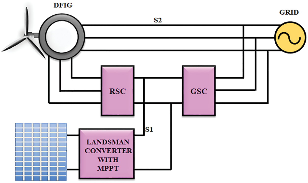
Figure 1: Proposed wind turbine DFIG-PV system
By utilizing the wind energy, the wind turbine produces current to drive the generator. The lifting and rotating forcesmake the blade to rotate. A shaft, which is connected to the gearbox helps to increase the rotating speed of the generator and to transform the mechanical energy into electrical energy by generating the magnetic field [23].
The power generated by the WECS is expressed as,
In which, Ρ denotes the intensity of air, V denotes the wind velocity, β signifies the Pitch angle, Cp denotes the Power coefficient, r signifies the Radius of turbine blade and λ signifies the tip velocity proportion.
The expression of λ is given as,
where, ω represents the angular veleocity.
The power coefficient Cp and the turbine’s output power are controlled by modifying the tip velocity percentageand adjusting the speed.
The DFIG uses conventional generator with some rotor potential [24]. The expressions of 3-phase DFIG in a synchronous rotating dq reference frame is represented as:
In which, the angular velocity of synchronous reference frame is denoted as ωs, sωs = (ωs − ωe) is known as slip recurrence and slip is denoted as s, ωe denotes the angular velocity that is related to the mechanical velocity of generator via the Pole number as ωe = p/2ωr with stator and rotor resistance and inductance are denoted as Rs, Rr, Ls and Lr, mutual inductance is denoted as Lm and rotational velocity of rotor is denoted as ωr. The developed torque from the double fed induction generator is expressed as;
where ‘p’ is pair of poles
The real and reactive power of stator and rotor for DFIG is represented as,
where, the loss of power linked with rotor and stator resistances are omitted.
3.1 Control Techniques of DFIG
The DFIGis consisted of rotor terminal and grid terminal controls. The real and reactive powers are are controlled by the GSC [25].
3.1.1 Control of RSC Using PI Controller
The primary aim of the GSC is to maintain a fixed DC potential irrespective of its value and rotor power flow direction. To satisfy this demand, a hysteresis controller is positioned with stator potential location as depicted in Fig. 2. It maintains the stability of DC potential and compensates the reactive power across the grid.
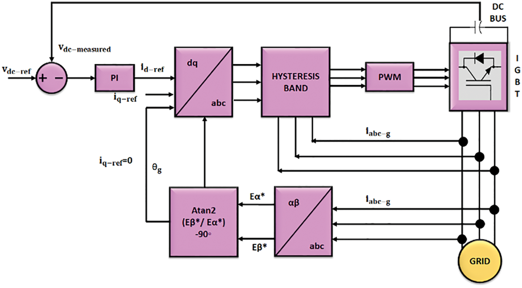
Figure 2: Architecture of proposed method for GSC
The required power supply of RSC is generally produced by the VSC, which is linked with the grid at the stator terminal of generator. The utilization of the capacitor eliminates the ripples and keeps the DC potential as smooth. The PWM converter is used for maintaining constant DC potential. The GSC provides real power demand of RSC. It is easy to operate the converter with flow reference system. Hence, a hysteresis control is adopted, in which the error among the expected and measured current is directed to control the potential of traditional sine PWM converter for achieving the necessary power factor [26]. The architecture of GSC is given in Fig. 2.
The voltages at the grid side in dq reference frame is expressed as,
where, vd, vq are the grid voltages in d-q frame; vdl, vql are the grid side inverter voltage in dq frame; id, iq are the grid currents in dq frame. The filter inductance and resistance are denoted as L and R whereas the rotational recurrence is denoted as ω. The dynamic and reactive powers are mentioned as:
The position of the grid potential is calculated as,
where, the grid voltage components of α and β are denoted vα and vβ. As the grid potential is having a fixed magnitude, vd also has a fixed magnitude.
The DFIG gives the output power to both the stator and rotor windings of DFIG. Though, the velocity is slightly varied over the synchronous speed, the power factor is attained by using the generators. The rotor current iabc−r of the generator is changed into the dq component as idr and iqr. The current iqr produce magnetic lines in the gap, which is lined up with the rotating motion to link with stator. In addition, these components produce flux, which is perpendicular to the vector. The generated torque is the vector multiplication of two vectors.Therefore, the current idr contribute to the torque production in a wider range. The current idr controls the reactive power, which is fed into the generator. The exact order of currents idr and iqr is allowed by controlling the real and reactive power on the stator side.
The significant objective of this controller is to get correct location of the rotational magnetic flux in vector space to get the outline of rotating reference. As stated by Lenz’s law of electromagnetic theory, the potential of stator is derived from the stator flux links. Thus, the 3Ф stator potential and current are converted into αβ component. The stator flux in αβ reference equation is represented as,
To arrange the synchronously rotating dq reference casing with the stator motion, the data of stator flux gradientis obtained from the subsequent expression,
The angle θs provides the correct location of rotating magnetic flux of stator. The rotor is rotating and promptly positioned at gradient θr. With a mentioned casing fixed rotor, the stator magnetic field is at θs − θr, called as the “slip angle”. The reference frame is aligned to create a simple representation.
As the torque is depended on current iqr it is controlled by voltage
In this control mechanism shown in Fig. 3, the rotor current (idr, iqr) has to be regulated to follow the corresponding references, idr−ref and iqr−ref.
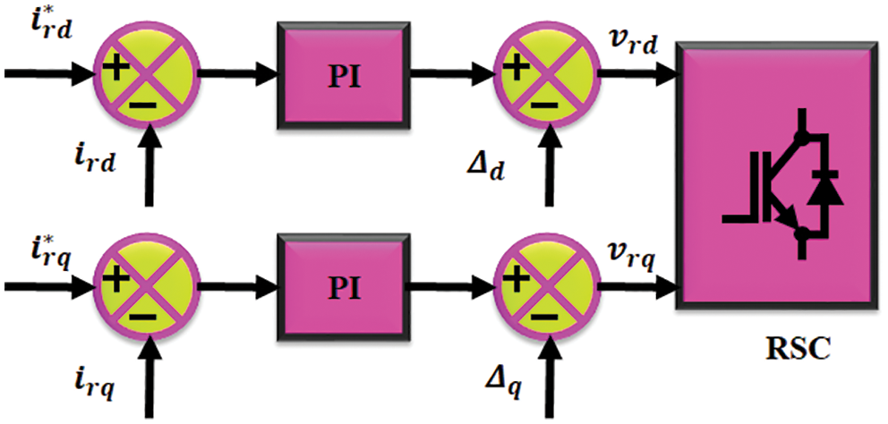
Figure 3: Control scheme of RSC
The q-axis current shows the generator real power whereas the d-axis current shows the reactive power. Eventually, the q-axis current is linked to the electromechanical torque of the generator and d-axis current is linked with DC potential.
The PWM controller operates on the generator’s rotor.The stator potential is positioned at rotor, which is shown in equation [27].
3.2 Control Techniques of Solar PV System
The non-reliable output of PV array makes it hard to achieve the proficient activity of the system. To obtain the optimal resultand to enhance the performance of the system, various MPPT (maximum power point tracking) techniquesare utilized [28]. Irrespective of fluctuations, the MPPT method constantly enhances the output power of power generating system in all circumstances. The MPPT is a basic and dependable method, which helps in the effective activity of sustainable power source. A GA-ANN based MPPT calculation is implemented in this study.
The DC-DC converters are playing a prominent role in enhancing the output voltage of PV [29]. The Landsman converter is one of the significant DC–DC converter, which has the ability of boosing the PV output in a wider range. The structure of the Landsman converter is represented in Fig. 4a.
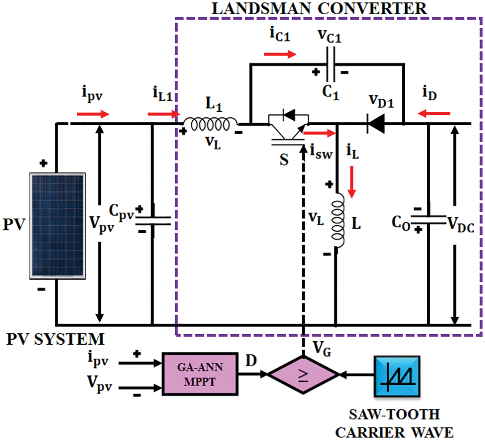
Figure 4(a): Landsman converter
The inductor in the input side removes all oscillations, which are caused by the switching devices. The Landsman converter works in CC Mode to ignore the variation in the irradiance level [30]. The working of converter is split into two modes as depicted in Figs. 4b and 4c.
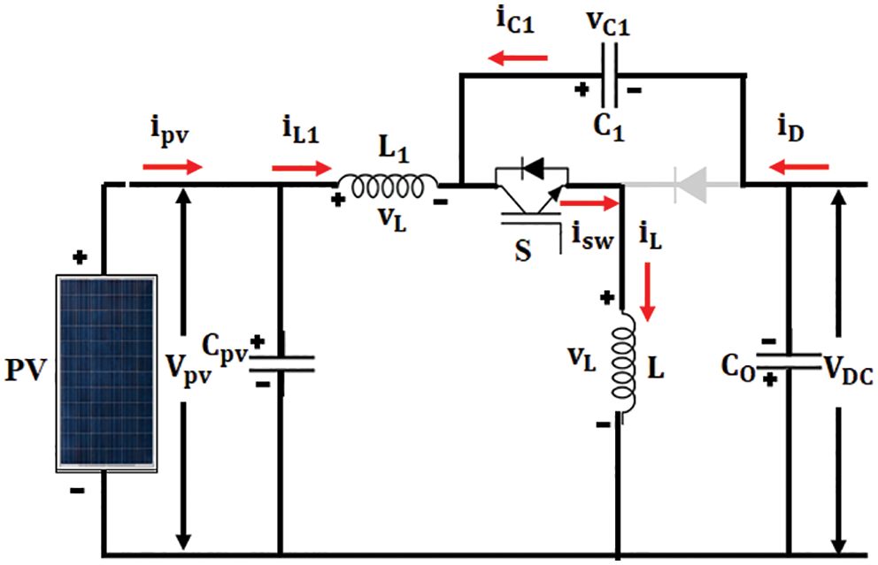
Figure 4(b): Mode I Operation

Figure 4(c): Mode II Operation
Mode I
Fig. 4b shows the arrangement of Mode I operation. In switch ON state, the diode is reverse biased. Hence, the inductor current IL passes through switch S. If VC1 is greater than the output voltage Vdc, the intermediate capacitor, C1 discharges through the switch.Then inductor L transfers the charge to the output. Thus, the voltage across the capacitor vc1 is reduced and inductor current iL is increased, as portrayed in Fig. 4b.
Mode II
Fig. 4c shows the arrangement of mode II operation.The diode is forward biased in switch OFF condition. The inductor current passes through diode IL. Through diode, inductor L transfer its charge to the output side. C1 is charged by the energy from source and inductor L1 [31]. Thus, intermediate capacitor vc1is increasedand the inductor current iLis reduced as depicted in Fig. 4c.
The current across L1,
In switch off state, the current through C1 is represented as,
In which,
D signifies the duty ratio and T signifies the switching period.
By using the above expression, the ripples in the voltage
By substituting
By normalizing the above expression, it is given as,
where, Idc signifies the Current, which is produced by the Landsman Converter.
By substituting Eq. (31) in (29),
3.2.2 Control of Landsman Converter for DC Link Voltage
The GA-ANN based MPPT gives optimum power from the solar energy, whichaids in increasing the efficacy of the converter. The Landsman converter is used to improvise the solar power through MPPT approach. Through the intelligent switching called GA-ANN, the array voltage is controlled and maintained at maximum level.
3.2.3 GA Optimized ANN Controller
The ANN is one of the best techniques, which provides excellent outcome than other algorithms. The ANN consists 3 nodes like input, hidden and output nodes. The data moves only in forward directionfrom one node to another node. This network has no cycles or loops. Fig. 5a depicts the block representation of ANN. The neural network in this type has two input nodes, a hidden layer and two output layer.In this network, the back propagation training scheme is utilized.
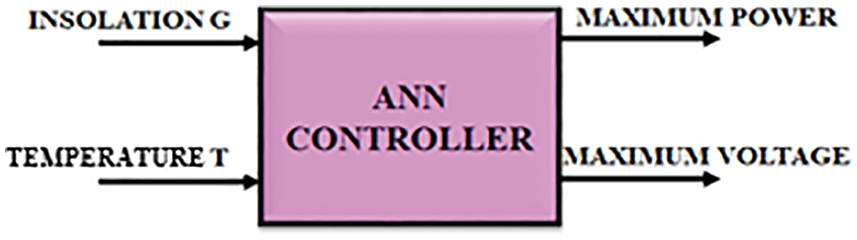
Figure 5(a): ANN block diagram
The block representation of MPPT method is depicted in Fig. 5b. In this method, ANN is used to find out the maximum potential. It is well trained by a set of input and output variables, which are regulated through the Genetic Algorithm.
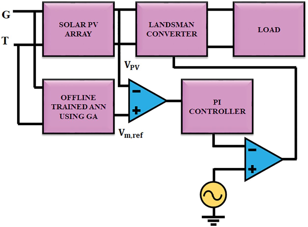
Figure 5(b): GA optimized ANN controller
Find out the values of X = (x1, x2, …., xn), and therefore F(x) maximizes the power in solar PV array.
Assume variable Xi = IPV, solar PV Current
The condition is IPVmax ≥ IPV ≥ IPVmin
Here
The implementation steps of GA are shown below,
• Determine the objective function and find out the design values.
• Assume initial starting population
• Estimate the population through the objective function.
• Check for convergence. If contented, then hold or else continue the process.
• Initiate the reproduction operation by registering the genetic operations like Selection, Crossover, and Mutation.
• Develop novel generations. Move on to third step.
The entire system is validated in MATLAB. Fig. 6 shows input voltage of the Landsman Converter. The Landsman converter minimizes the ripples in the output voltage of PV and increases the voltage gain. The PV output voltage is fedto the DC capacitor voltage in parallel. Fig. 7 represents the output voltage of Landsman converter. A constant potential is given to DC the link capacitor in DFIG This constant voltage minimizes the power quality problems and increases the stability of DFIG output voltage. The GA optimized ANN controller maintains output voltage ofthe converter as constant without any transients. The controller takes less time for reaching the steady value. The GA-ANN controller delivers better performance than the PI controller.
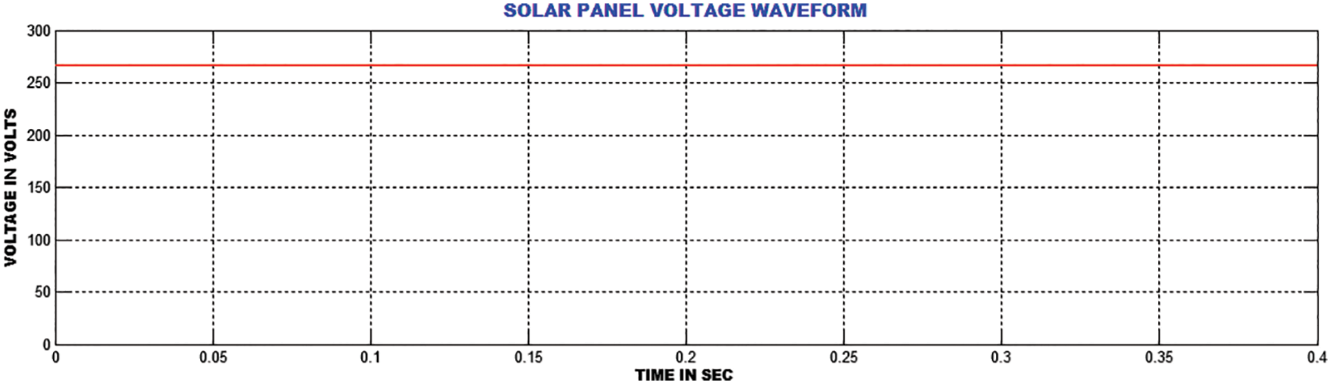
Figure 6: Source voltage to the landsman converter
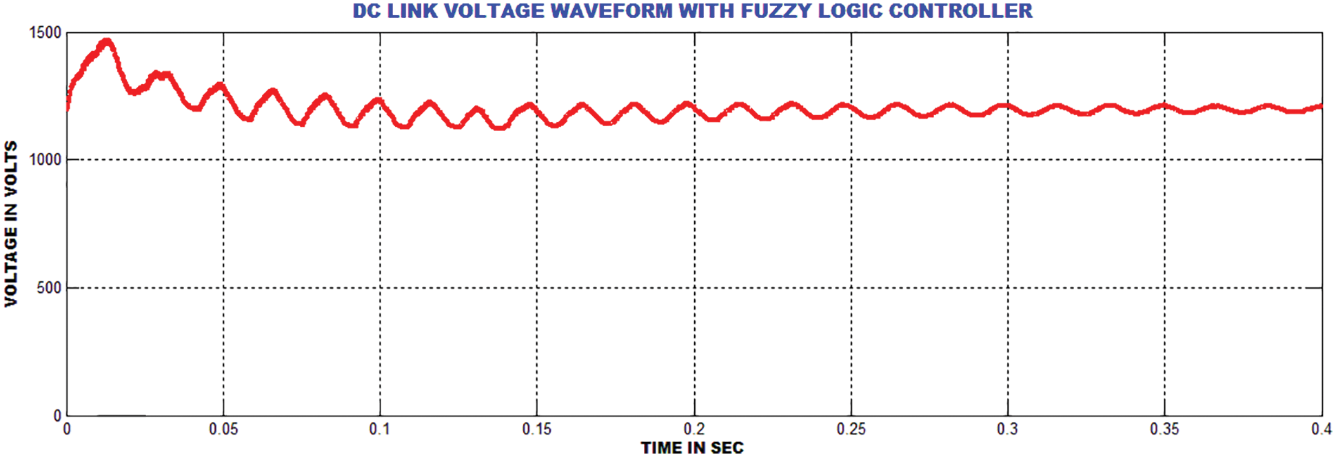
Figure 7: Output voltage of the landsman converter (DC link)
Fig. 8 shows the output voltage of generator and Fig. 9 highlights the output current of generator. It is noted from the waveform that the peak overshoot is extended up to 0.3 s. Fig. 10 shows the rotor speed of twind turbine system. Figs. 11 and 12 show the real and reactive power waveforms of proposed system. The proposed current control strategy decreases the reactive power in a wider range.

Figure 8: DFIG grid output voltage waveform
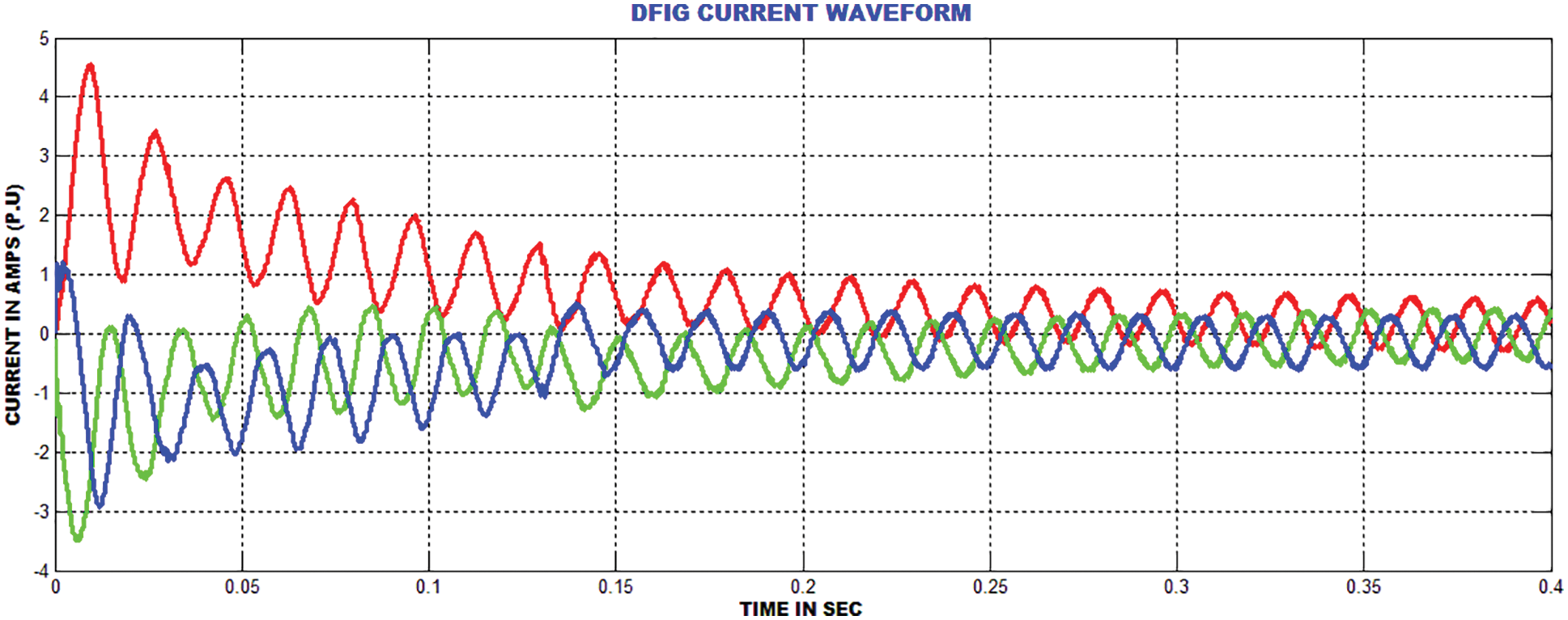
Figure 9: DFIG grid current waveform
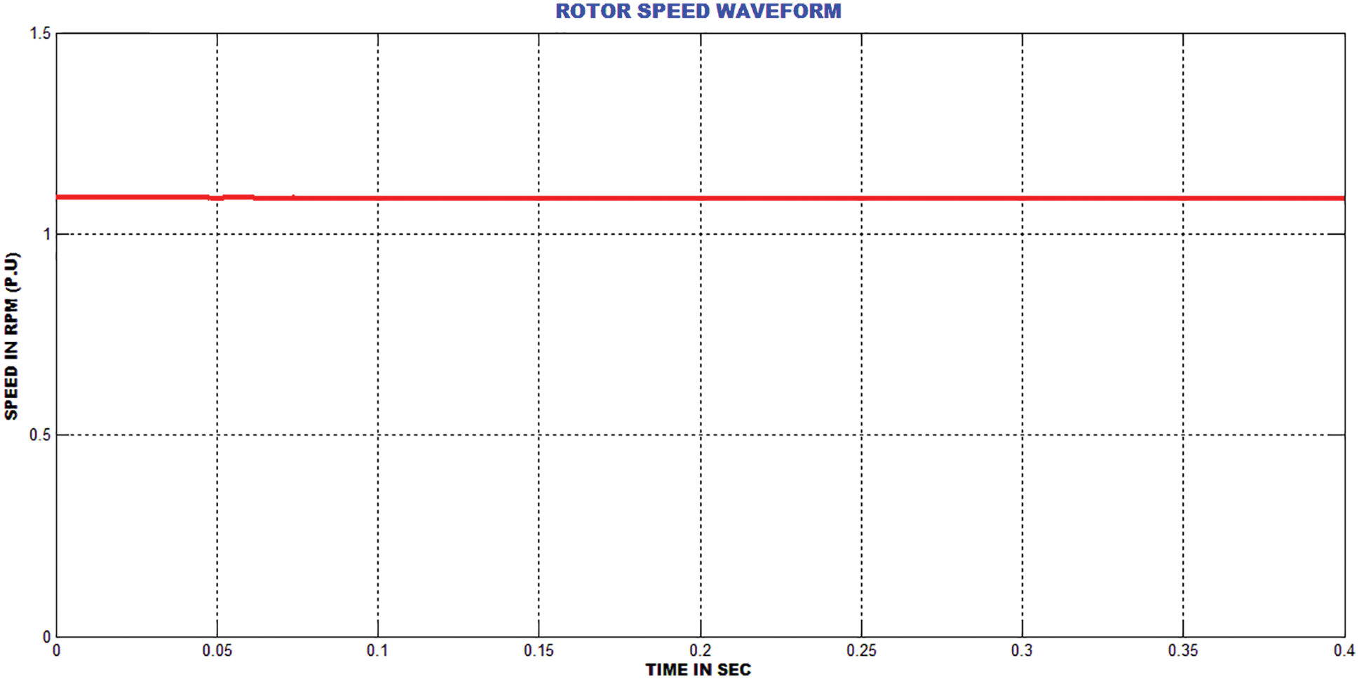
Figure 10: DFIG rotor velocity waveform
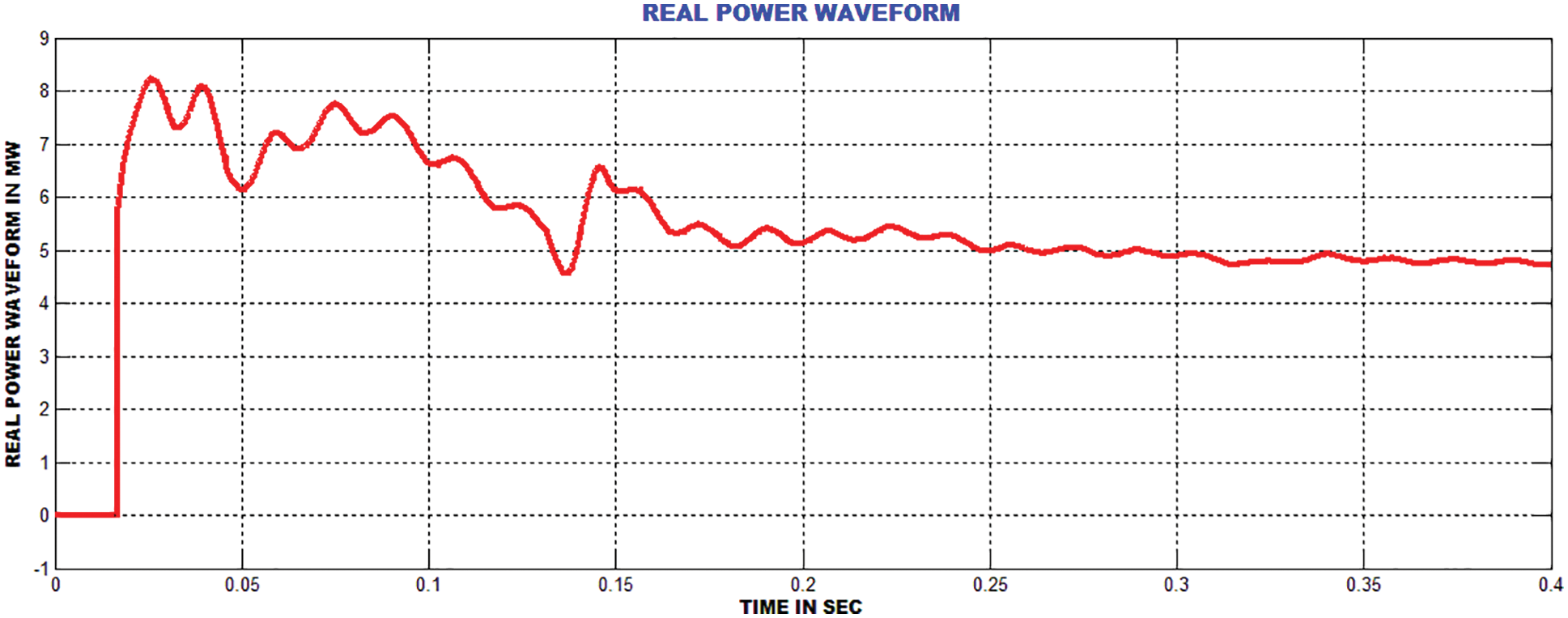
Figure 11: Real power waveform
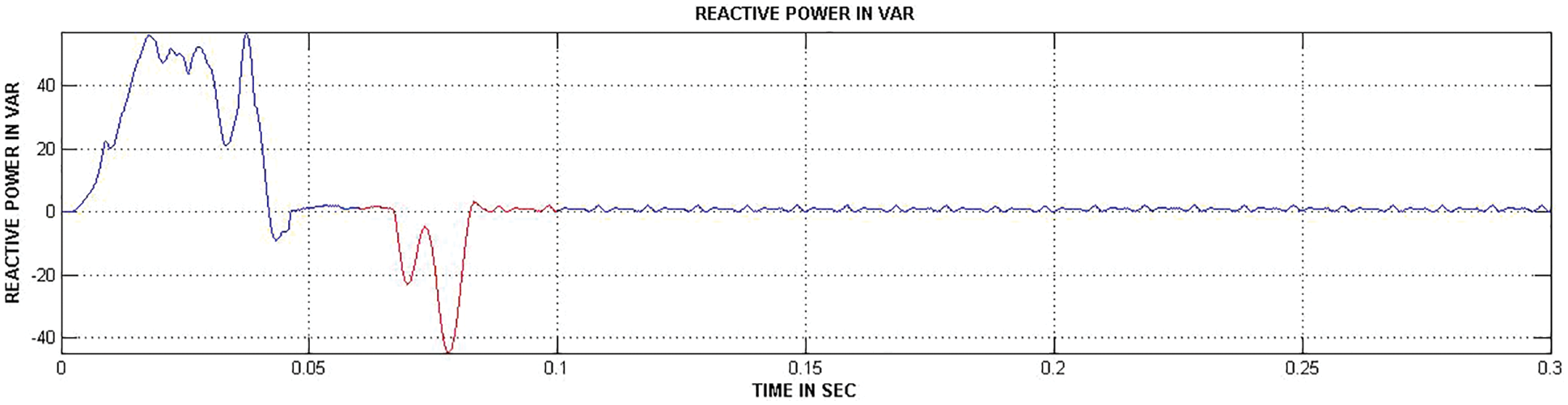
Figure 12: Reactive power waveform
Figs. 13 and 14 show the THD values of PI and GA-ANN controllers. The GA-ANN delivers better performance thanthe PI controllersin reducing the THD value.The obtained THD value satisfies the IEEE standard. The GA-ANN based DFIG increases the voltage stability and efficiency. In addition, this system achieves the reactive power compensation.

Figure 13: PI controller based GRID current THD waveform

Figure 14: GA-ANN based GRID current THD waveform
The experimental prototypeof the developed scheme is depicted in Fig. 15. The DC-link potential is controlled through conventional PI and GA-ANN controllers as depicted in Figs. 16 and 17. In addition, the grid potential and current waveforms are depicted in Fig. 18. The graphical representations of THD values for hardware results are depicted in Figs. 19, 20 grid current THD comparison mentioned in Tab. 1.
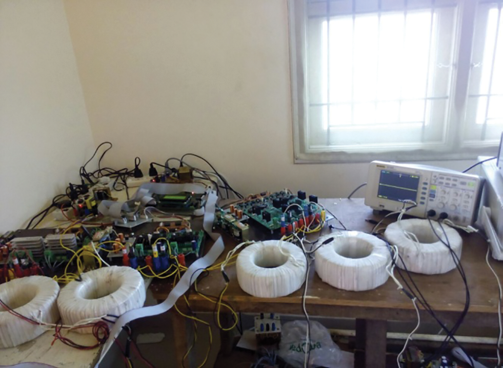
Figure 15: Experimental setup
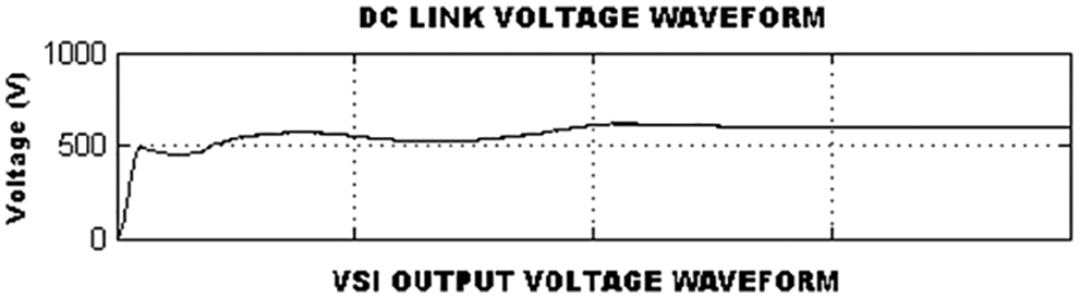
Figure 16: DC-link voltage using PI controller
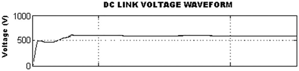
Figure 17: DC-link voltage using GA-ANN controller

Figure 18: Grid voltage and current

Figure 19: Hardware result PI controller based GRID current THD waveform

Figure 20: Hardware result GA-ANN controller based GRID current THD waveform

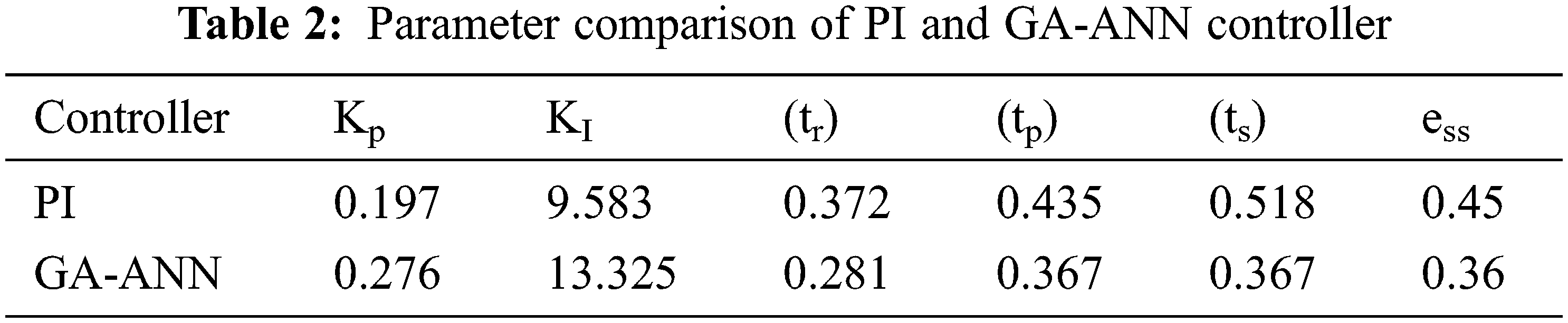
The parameters of conventional PI and GA optimized ANN controllers are listed in Tab. 2. It clearly reveals that the converter reaches the maximum value more quickly by GA-ANN based controller than PI controller. The steady state error is comparatively less in the GA-ANN.
Tab. 3 shows the comparison forthe gain values of different converters. With GA optimized ANN controller, the converter has achieved maximum gain of 4, which is comparatively better than the other converters.

The compensation of real and reactive power in the proposed WECS using DFIG is accomplished under different rotor speeds. The analysis of GSC and RSC control actualizes the real and reactive powers. The Landsman converter has improvised the PV output voltage, which assists in enhancing the performance of the system. The control mechanism is operated by controlling rotor side converter for regulating real and reactive powers.The GSC balances the DC potential as constant. The outcomes are exhibited to validate the hypothetical design of control system and its utilization in the wind power system. The Solar based Landsman converter system maintains DC voltage as constant by using GA-ANN based MPPT. The source current THD is observed as 1.93% and 2.4% for simulation and hardware implementation respectively.
Acknowledgement: Thanks to the guide and the reviewers.
Funding Statement: The authors received no specific funding for this study.
Conflicts of Interest: The authors declare that they have no conflicts of interest to report regarding the present study.
1. A. P. Tennakoon, A. Arulampalam, J. B. Ekanayake and S. G. Abeyratne, “Modeling and control of doubly fed induction generators (DFIG) for wind energy applications,” in IEEE First Int. Conf. on Industrial and Information Systems, Tirtayasa, Indonesia, pp. 8–11, 2006. [Google Scholar]
2. H. S. Ko, G. G. Yoon, N. H. Kyung and W. P. Hong, “Modeling and control of DFIG-based variable-speed wind-turbine,” Electric Power System Research, Elsevier, vol. 78, no. 11, pp. 1841–1849, 2008. [Google Scholar]
3. Z. Miao, L. Fan, D. Osborn and S. Yuvarajan, “Control of DFIG-based wind generation to improve interarea oscillation damping,” IEEE Transaction on Energy Conversation, vol. 24, no. 2, pp. 415–422, 2009. [Google Scholar]
4. Y. Wang, L. Xu and B. W. Williams, “Compensation of network voltage unbalance using doubly fed induction generator based wind farms,” IET Renewable Power Generation, vol. 3, no. 1, pp. 12–22, 2009. [Google Scholar]
5. R. Pena, S. R. Cardena, E. Escobar, J. Clare and P. Wheeler, “Control strategy for a doubly-fed induction generator feeding an unbalanced grid or stand-alone load,” Electric Power System Research, Elsevier, vol. 79, no. 2, pp. 355–364, 2009. [Google Scholar]
6. O. G. Bellmunt, A. J. ferre and A. S. J. B. Jan, “Ride-through control of a doubly fed induction generator under unbalanced voltage sags,” IEEE Transaction on Energy Conversation, vol. 23, no. 4, pp. 1036–1045, 2008. [Google Scholar]
7. L. Xu, “Enhanced control and operation of DFIG-based wind farms during network unbalance,” IEEE Transaction Energy Converters, vol. 23, no. 4, pp. 1073–1081, 2008. [Google Scholar]
8. S. Puchalapalli, B. Singh, S. K. Tiwari and P. K. Goel, “Design and analysis of grid-interactive DFIG based WECS for regulated power flow,” IEEE Transactions on Industry Applications, vol. 56, no. 5, pp. 5396–5407, 2020. [Google Scholar]
9. S. Velpula, R. Thirumalaivasan and M. Janaki, “Stability analysis on torsional interactions of turbine-generator connected with DFIG-WECS using admittance model,” IEEE Transactions on Power Systems, vol. 35, no. 6, pp. 4745–4755, 2020. [Google Scholar]
10. S. Puchalapalli and B. Singh, “A novel control scheme for wind turbine driven DFIG interfaced to utility grid,” IEEE Transactions on Industry Applications, vol. 56, no. 3, pp. 2925–2937, 2020. [Google Scholar]
11. V. C. Ganti, B. Singh, S. K. Aggarwal and T. C. Kandpal, “DFIG-Based wind power conversion with grid power leveling for reduced gusts,” IEEE Transactions on Sustainable Energy, vol. 3, no. 1, pp. 12–20, 2012. [Google Scholar]
12. M. Morey and V. Virulkar, “Rotor flux observer for speed sensorless IFOC induction motor at low speeds,” in IEEE Int. Conf. on Power Electronics, Drives and Energy Systems (PEDES), Chennai, India, pp. 1–6, 2018–2019. [Google Scholar]
13. H. X. Hui and H. C. Cen, “Harmonic suppression for low speed sensorless control of spmsm based on high voltage frequency pulsating signal injection,” in IEEE Information Technology, Networking, Electronic and Automation Control Conf. (ITNEC), Chengdu, China, pp. 686–690, 2019. [Google Scholar]
14. S. Mondal and D. Kastha, “Maximum active and reactive power capability of a matrix converter-fed DFIG-based wind energy conversion system,” IEEE Journal of Emerging and Selected Topics in Power Electronics, vol. 5, no. 3, pp. 1322–1333, 2017. [Google Scholar]
15. J. Cai, P. Li and Y. Huang, “Speed sensorless direct torque control of direct-drive permanent magnet wind generator,” in Chinese Automation Congress (CAC), Xi’an, China, pp. 1355–1360, 2018. [Google Scholar]
16. K. Rajesh, A. D. Kulkarni and T. Ananthapadmanabha, “Modeling and simulation of solar PV and DFIG based wind hybrid system,” Procedia Technology, vol. 21, pp. 667–675, 2015. [Google Scholar]
17. N. K. S. Naidu and B. Singh, “Grid-interfaced DFIG-based variable speed wind energy conversion system with power smoothening,” IEEE Transactions on Sustainable Energy, vol. 8, no. 1, pp. 51–58, 2017. [Google Scholar]
18. S. Surendran and V. Kumar, “Neural network based pi controller parameter calculation on a boiler drum level system,” Procedia Technology, ICETES, vol. 24, pp. 1616–1622, 2016. [Google Scholar]
19. N. S. Kumar, V. Sadasivam and H. M. A. Sukriya, “A comparative study of PI, fuzzy, and ANN controllers for chopper-fed dc drive with embedded systems approach,” Electric Power Components and Systems, vol. 6, no. 7, pp. 680–695, 2008. [Google Scholar]
20. K. Karabacak and N. Cetin, “Artificial neural networks for controlling wind–PV power systems: A review,” Renewable and Sustainable Energy Reviews, vol. 29, pp. 804–827, 2014. [Google Scholar]
21. E. C. Navarrete, M. T. Perea, J. C. J. Correa, R. V. C. Serrano and J. G. R. Moreno, “Expert control systems for maximum power point tracking in a wind turbine with PMSG: State of the art,” Applied Science, vol. 9, no. 12, pp. 2469, 2019. [Google Scholar]
22. J. Samanes, E. Gubia, J. Lopez and R. Burgos, “Sub-synchronous resonance damping control strategy for DFIG wind turbines,” IEEE Access, vol. 8, pp. 223359–223372, 2020. [Google Scholar]
23. C. M. Hong, C. H. Chen and C. S. Tu, “Maximum power point tracking-based control algorithm for PMSG wind generation system without mechanical sensors,” Energy Converters Management, vol. 69, pp. 58–67, 2013. [Google Scholar]
24. Y. Zhang, L. Zhang and Y. Liu, “Implementation of maximum power point tracking based on variable speed forecasting for wind energy systems,” Processes 2019, vol. 7, pp. 158, 2019. [Google Scholar]
25. X. Jiao, W. Meng, Q. Yang, L. Fu and Q. Chen, “Adaptive continuous neural pitch angle control for variable-speed wind turbines,” Asian Journal Control, vol. 21, no. 4, pp. 1966–1979, 2019. [Google Scholar]
26. L. G. Meegahapola, T. Littler and D. Flynn, “Decoupled-DFIG fault ride-through strategy for enhanced stability performance during grid faults,” IEEE Transaction on Sustainable Energy, vol. 1, pp. 152–162, 2010. [Google Scholar]
27. J. Mohammadi, S. V. Zadeh, S. Afsharnia and E. Daryabeigi, “A combined vector and direct power control for DFIG-based wind turbines,” IEEE Transaction on Sustainable Energy, vol. 5, pp. 767–775, 2014. [Google Scholar]
28. Barambones, J. A. Cortajarena, P. Alkorta and J. M. G. D. Durana, “A Real-time sliding mode control for a wind energy system based on a doubly fed induction generator energies,” Energies, vol. 7, pp. 6412–6433, 2014. [Google Scholar]
29. B. Han, L. Zhou and Z. Zhang, “LIDAR-Assisted radial basis function neural network optimization for wind turbines,” IEEE Transaction on Electrical and Electronics Engineering, vol. 13, pp. 195–200, 2017. [Google Scholar]
30. C. Wei, Z. Zhang, W. Qiao and L. Qu, “An adaptive network-based reinforcement learning method for MPPT control of PMSG wind energy conversion systems,” IEEE Transaction on Power Electronics, vol. 31, pp. 7837–7848, 2016. [Google Scholar]
31. N. Priyadarshi, S. Padmanaban, J. B. H. Nielsen, F. Blaabjerg and M. S. Bhaskar, “An experimental estimation of hybrid ANFIS–PSO-based MPPT for PV grid integration under fluctuating sun irradiance,” IEEE Systems Journal, vol. 14, no. 1, pp. 1218–1229, 2020. [Google Scholar]
32. R. Kushwaha and B. Singh, “Interleaved landsman converter fed EV battery charger with power factor correction,” IEEE Transactions on Industry Applications, vol. 56, no. 4, pp. 4179–4192, 2020. [Google Scholar]
 | This work is licensed under a Creative Commons Attribution 4.0 International License, which permits unrestricted use, distribution, and reproduction in any medium, provided the original work is properly cited. |