DOI:10.32604/iasc.2023.024679
| Intelligent Automation & Soft Computing DOI:10.32604/iasc.2023.024679 | |
| Article |
Performance Analysis of Optimization Based FOC and DTC Methods for Three Phase Induction Motor
Department of EEE, St. Xavier’s Catholic College of Engineering, Nagercoil, 629003, India
*Corresponding Author: V. Jesus Bobin. Email: jesusbobin12345@gmail.com
Received: 27 October 2021; Accepted: 22 December 2021
Abstract: Three-phase induction motors are becoming increasingly utilized in industrial field due to their better efficiency and simple manufacture. The speed control of an induction motor is essential in a variety of applications, but it is difficult to control. This research analyses the three-phase induction motor’s performance using field-oriented control (FOC) and direct torque control (DTC) techniques. The major aim of this work is to provide a critical evaluation of developing a simple speed controller for induction motors with improving the performance of Induction Motor (IM). For controlling a motor, different optimization approaches are accessible; in this research, a Fuzzy Logic Controller (FLC) with Fractional Order Darwinian Particle Swarm Optimization (FODPSO) algorithm is presented to control the induction motor. The FOC and DTC are controlled using FODPSO, and their performance is compared to the traditional FOC and DTC technique. Each scheme had its own simulation model, and the results were compared using hardware experimental and MATLAB-Simulink. In terms of time domain specifications and torque improvement, the proposed technique surpasses the existing method.
Keywords: Three-phase induction motor; fractional order darwinian particle swarm optimization; speed control; field-oriented control; direct torque control; fuzzy logic controller
There are several methods for managing the torque of an induction motor control system, DTC and FOC methods have gained popularity owing to their ability to successfully follow speed and torque standards despite disturbances in load factors [1,2]. Blaschke devised FOC method, often referred as vector control, in 1970. The FOC method’s primary field current is estimated to reduce copper and iron losses in this method [3]. Maghfiroh et al. and colleagues [4] presented a simulation of DTC-based speed control of an induction motor. Fuzzy-(Proportional Integral Derivative) PID was utilised for simulation under both loaded and unloaded conditions. They were comparing fuzzy-PID to traditional PID. At no-load test, the proposed technique consumes 4.5% additional energy. At load test, fuzzy PID consumes 1.03% less energy than classical PID. M. Abassi, A. Khlaief, and colleagues [5] presented a performance analysis of DTC and FOC approach in 2015. The disadvantages of this strategy include the need for position knowledge and mechanical sensors. Nanjib EI Quanjili, Aziz Derouich, et al., offered a review on recent DTC enhancement approaches for IM drives in 2019.
Due to the order reduction, easy implementation through power converters, great robustness and disturbance rejection, sliding mode control is regarded as the suitable technology for the robust nonlinear control of IM drives [6]. The DTC outperforms field-oriented control in terms of benefits. Direct torque control is less susceptible to external disturbances, additional resilient to criterion fluctuations, and does not require reference frame transformation [7]. The dynamic response is also good when compared to the FOC method. The simulation of these two methods with Fuzzy-FODPSO [8,9] is presented in this study, and the results are evaluated for a 3-
Several studies on FOC and DTC, including the use of further types of controllers to improve the quality of motor’s control system. Another problem of these articles and researches are primarily focused with evaluation of performance, which presupposes that everything is working smoothly that may always not be the case. As a result, these comparison studies include two power quality issues: short interruption and voltage sag [10]. A conceptual analysis of DTC [11] and other motor drive systems that outlined the essential concepts of DC drive, scalar control, flux vector and DC drive. On the other hand, several studies on FOC and DTC methods are individually, there has been published [12–15]. The fuzzy controller is insensitive to parameter alterations; however, using the PSO-based optimization technique, we achieve a more logical choice of gains to make the system more resilient [16]. For smooth operations, a Genetic Algorithm (GA)-based approach limits the fast fluctuation in motor speed to the best reference value [17].
Many studies have demonstrated that, FLC controllers are simple to design; nonetheless, FLC performance is dependent on the rule basis, membership functions (MFs) and number of rules. These parameters are established by a time-consuming error and trial approach. To circumvent these constraints, FLC design optimization approaches employ a differential optimization algorithm to construct FLC and regulate the speed of induction motors [18,19]. The FODPSO technique is used in this study to optimize the functionality of the induction motor speed controller by optimizing strictures and determining the limits and ideal values for MFs output and input.
Furthermore, previous works investigates the similarities between DTC and FOC by re-evaluating the core ideas of both and looking for methods to integrate the two to build a control scheme that is both more accurate and faster. As a consequence, this study is compared with previous methodologies, with extra similar criteria included. The suggested work discusses the operation of FOC and DTC method in Segment 2, the function of FLC is explained in Segment 3, FODPSO approach is explained in Segment 4, the proposed Fuzzy-FODPSO based DTC and FOC methods are clearly explained in Section 5, the simulated outcome and comparison of different techniques are discussing in Segment 6, and conclusion in Segment 6.
2 Field Oriented Control and Direct Torque Control method
2.1 Field Oriented Control method
Field Oriented Control (FOC) is the most often utilised control approach for high-performance induction motor applications. FOC method employs orthogonal transformation, where abc coordinates are mapped to dq0 coordinates. The flux and torque components will be decoupled which leads to independent control using quadrature axis or direct axis currents. The output voltage can be regulated using a Propotional Integral (PI) controller thus the transient response of torque controller will be limited. The FOC system consists of Voltage Source Inverter (VSI), Induction motor, PI based controller, Current control-based Pulse Width Modulation (PWM) block. The rotor speed (r) and reference speed
The main disadvantage is that the control’s orientation is particularly sensitive to rotor resistance, which lowers the control’s resilience, high complexity and Coordinate transformation necessary. This limitation can be overcome by proposed Fuzzy-FODPSO based FOC approach.
2.2 Direct Torque Control Method (DTC)
A torque controller, an IGBT-based VSI, and a speed controller comprise the direct torque control drive. When the reference and rotor speeds are compared, an error signal is generated. The PI controller analyses the speed error and generates reference torque
The rotor flux and stator flux and complex form can be represented as
Based on the current failure, the inverter current is attempted to remain within the hysteresis controller’s specified band.
In this case, the flux controller has a hysteresis band width of
3 Fuzzy Logic controller (FLC)
The FLC technique is highly beneficial for induction motor speed drives. FLC contains a predefined set of control rules, which are often developed from expert knowledge. The MFs of the linked input and output linguistic terms are commonly established on a shared discourse universe. Appropriate selection of output and input scaling factors (gains) or adjustment of other controller parameters are key jobs for the effective design of FLCs, which is frequently done through trial and error to get the finest control performance. The regulations are designed to meet the needs of the speed. FLC performance will improve when the number of rules is increased. Fig. 1 depicts the FLC’s block diagram.
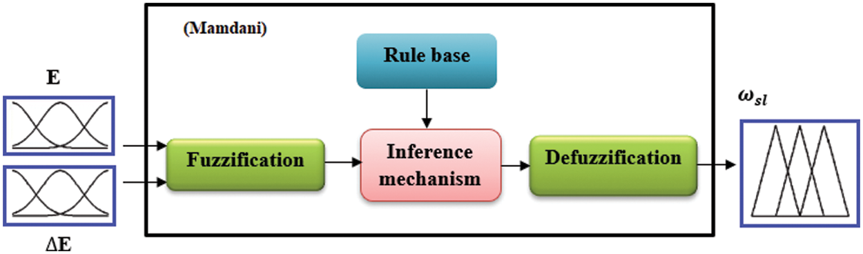
Figure 1: Fuzzy logic controller block diagram
The FLC’s main processes are fuzzification process, fuzzy rule base, inference, and defuzzification process. Defuzzification generates output in the form of a crisp value based on a given set of membership functions and rules. FLC is employed in the developed method to calculate the torque command current from the actual and reference speeds. As stated in the equations below, the input information consists of rotor speed’s error (E) and change of error (∆E).
The fuzzy speed controller’s inputs (E &
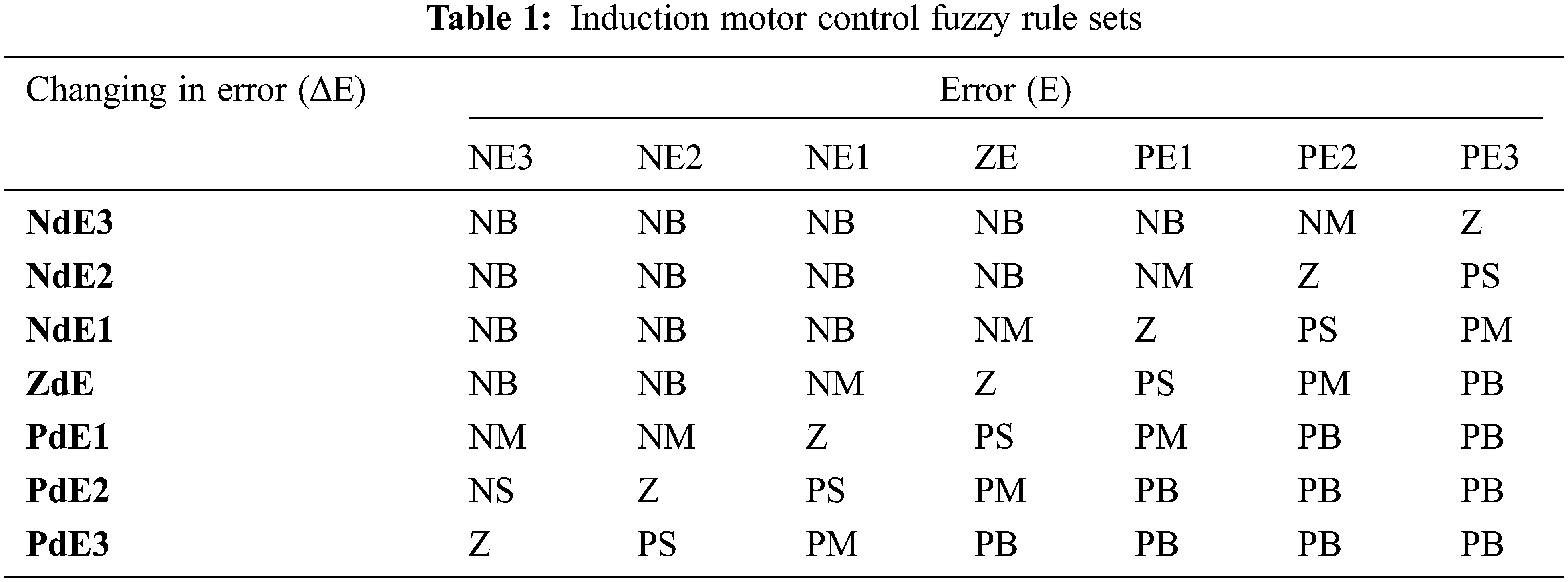
The second phase (fuzzification) expresses the inputs with easy linguistic value by grouping each input. The third step (inference) describes how the fuzzy speed controller makes the IM decisions using control rules and linguistic concepts. Mamdani procedures are utilised in this work, due of its simplistic construction and design. The fuzzy rules for induction motor control table shows in Tab. 1. The linguistic rules are written in the form of IF-THEN statements. The final phase in the FLC is defuzzification process. This method produces the controller’s output values as a crisp value. As an output, the defuzzified torque command
where, w
The proposed controller is utilised to alter the settings and govern the ideal values for the membership function variables using the FODPSO optimization technique.
4 Fractional Order Darwinian Particle Swarm Optimization
This part presents and denotes FO-DPSO, a novel way for controlling the DPSO optimization technique on Pires et al. method to the classic PSO [20,21]. Founded on the perception of fractional differential with
Where,
Where,
5 Proposed Fuzzy-FODPSO Based FOC method
The FLC speed controller is extensively used due to its adaptability in nonlinear controller systems, low implementation cost, and simplicity; it is not based on a design mathematical. The typical FLC has a limitation in specifying the bounds of the MF’s input and output. This segment describes how to enhance FLC by using FODPSO optimization to determine the optimal bounds of MF input and output.
The schematic of the proposed Fuzzy-FODPSO based FOC method is depicts in Fig. 2. It consists of IGBT based VSI inverter, power supply circuit, speed controller (PI), 3 phase diode rectifier, FOC unit and Fuzzy-FODPSO optimization-based speed controller circuit. The Fractional Order-DPSO is an optimization technique used to get the highest feasible output value. In this work, the rotor and reference speeds of the IM are compared, and the speed error is providing to the speed controller (PI controller) through this proposed optimization. Through the proposed FODPSO-FLC controller unit, the mistakes create the voltage command signals
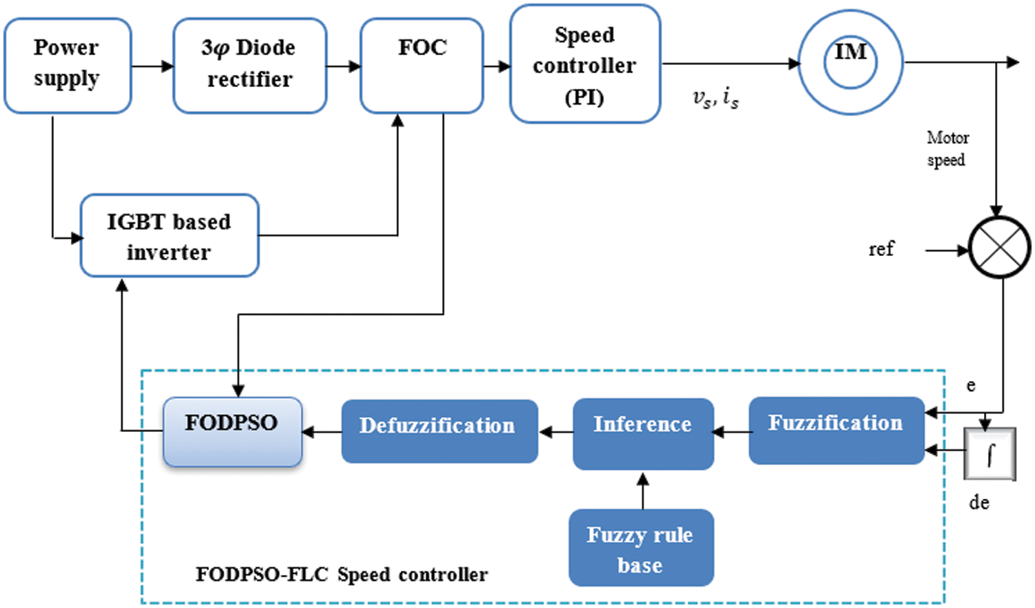
Figure 2: Block diagram of proposed Fuzzy-FODPSO based FOC method
6 Proposed Fuzzy-FODPSO Based DTC method
In this work, a FODPSO based fuzzy controller is suggested for use in the torque control loop of a DTC induction motor. The Fuzzy-FODPSO technique combines the Fractional Order Darwinian Particle Swarm Optimization algorithm and Fuzzy Logic Controller techniques. Fig. 3 shows the Fuzzy-FODPSO -based DTC block diagram. The goal of the work is to increase the DTC control’s performance while decreasing torque at low speeds. The proposed speed control of induction motor is revealed in Fig. 4.
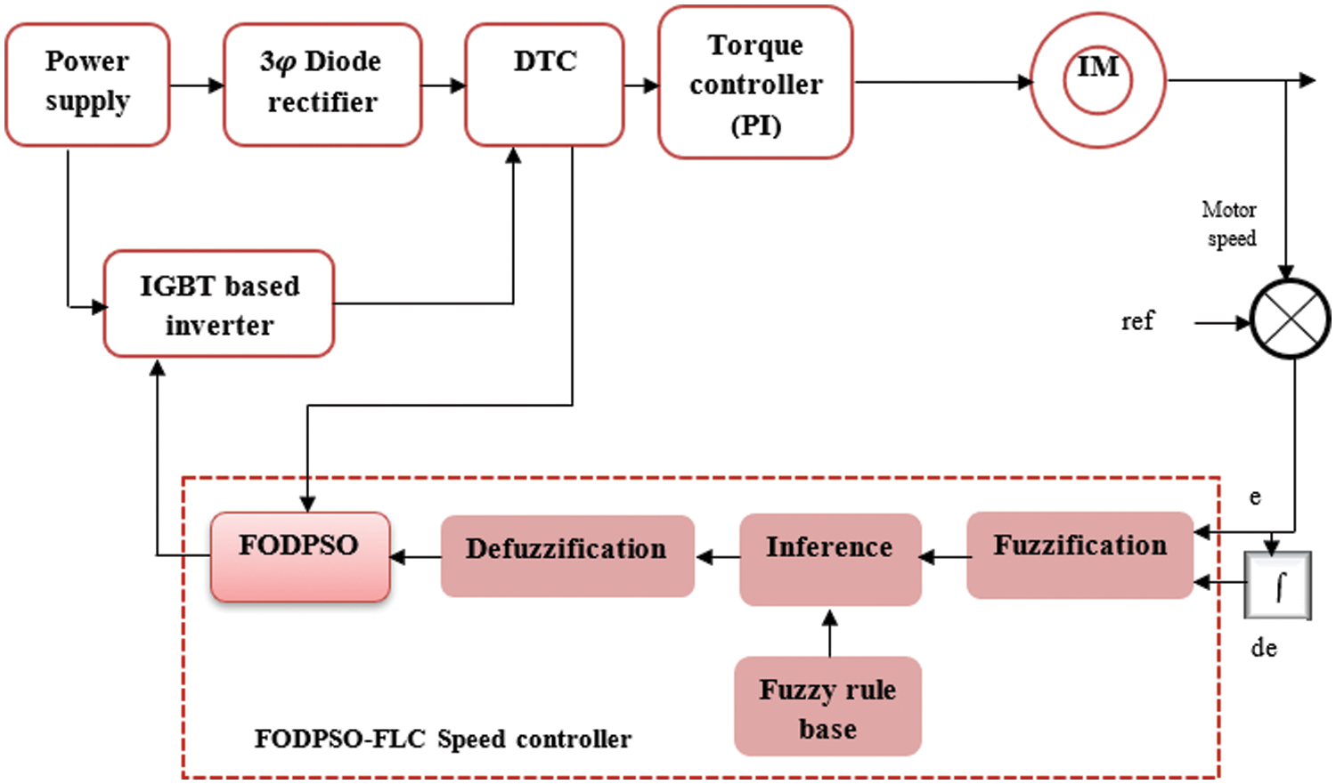
Figure 3: Block diagram of proposed Fuzzy-FODPSO based DTC method
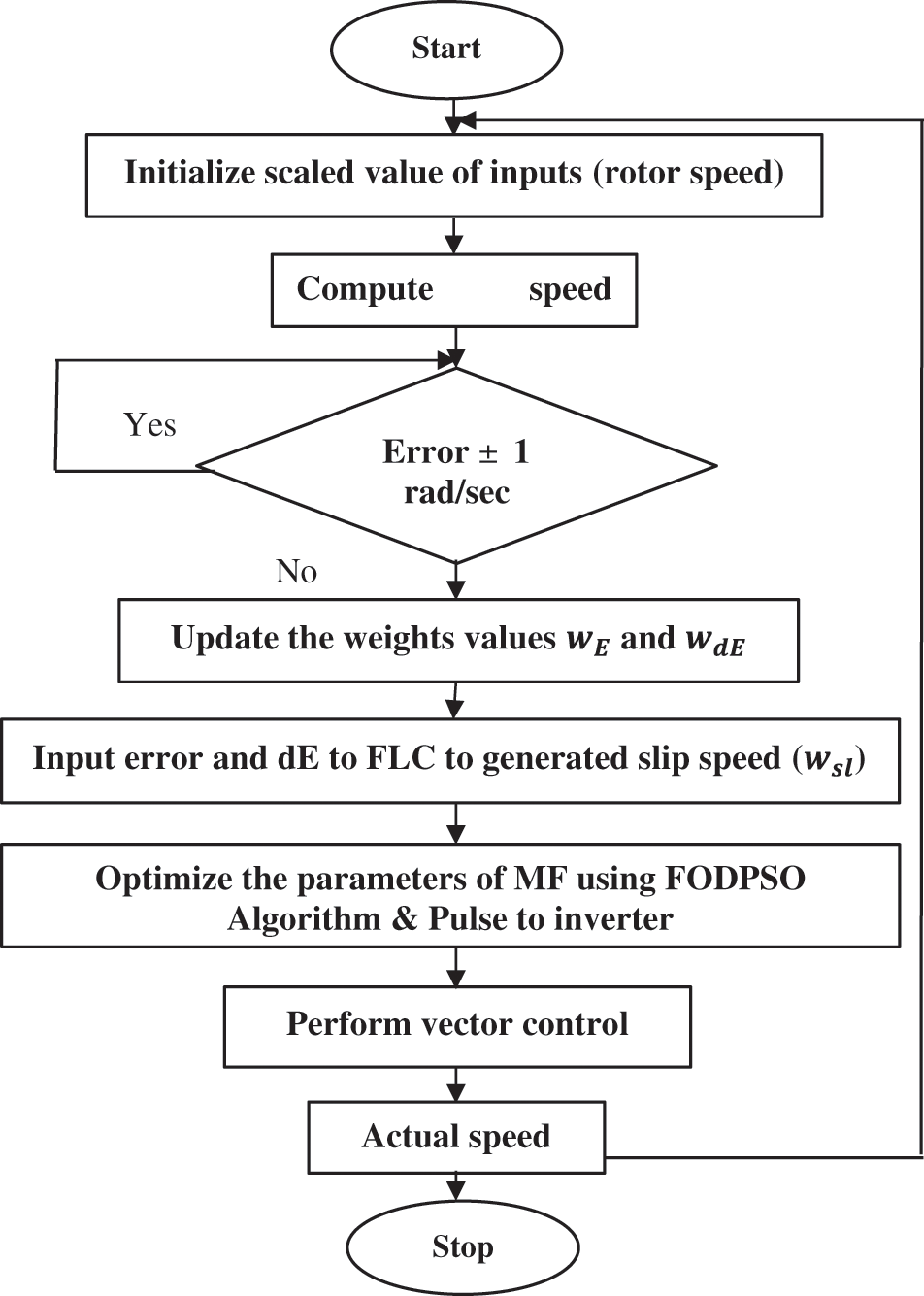
Figure 4: FODPSO based DTC method flow chart
From Fig. 3 the inputs are the difference between the commanded and actual values (E) and its derivative
From the proposed block diagram, the feedback element is the motor speed. The error signal (E) is derived by comparing the motor speed to the reference speed. The difference between the signal of error and the unit change in the error signal yields the change in the error signal (dE). The signals (E) and (dE) are fed into the FLC. In the fuzzy controller, the inputs are fuzzified and appropriate rules are defined. The output is subsequently acquired according to the rules, which is then defuzzified to obtain the control signal. The output variable is the pulse generator’s reference voltage vector. The gate signals for managing the inverter output frequency and voltage are created by the FODPSO generator based on the fuzzy logic control output. The FLC’s operation is determined by its membership function. The control signal is then utilised to change the inverter’s output frequency and voltage to achieve the required speed.
The stator flux module is composed of the following components:
The torque equation is as follows:
Motor torque and flux magnitudes are directly controlled in the DTC by controlling the stator flux vector. The DTC control technique is based on choosing the correct inverter switching pulses to directly regulate the speed and length of the stator flux vector. Here, the proposed fuzzy-FODPSO based speed control method is used well in the research to manage the speed of the induction motor with the help of the torque control method.
7 Simulation and Hardware Results
The suggested method is simulated in MATLAB. The associated outcomes are utilised to authorize the proposed Fuzzy-FODPSO based DTC and FOC approach, which governs the overall system performance. Fig. 5 depicts the simulation model of the proposed Fuzzy-FODPSO based FOC approach. As depicted, the induction motor is powered by an inverter. The inverter’s input is supposed to be a stiff dc source. As feedback, the motor output speed is compared to the reference speed, which may be adjusted accordingly. The error and change in error input are sent into the fuzzy logic controller, whose output alters the control signal based on the situation. A 3-phase reference current wave is created in response to the control signal, which works as a reference current wave, and that reference current wave is monitored by an appropriate gate pulse of the inverter. To track the reference current, a hysteresis current control system is used.
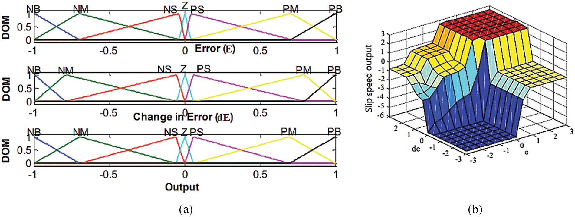
Figure 5: (a) FODPSO Optimized Input Output Membership Functions of fuzzy controller, (b) Output surface of Slip speed
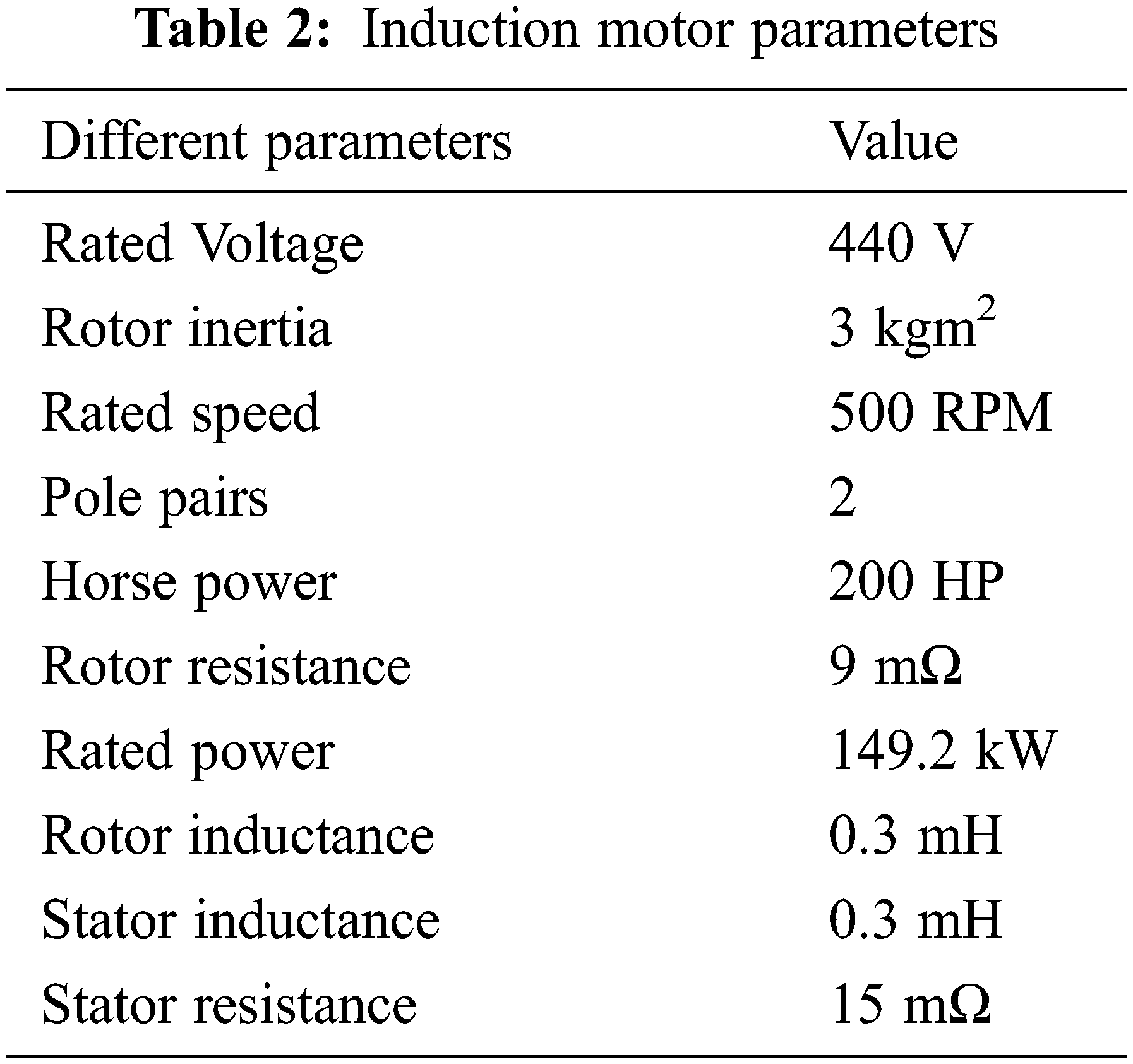
A sensor-less field-oriented control of IM drive for a 200HP AC motor is developed using MATLAB-Simulink. As a result of using the Model Referencing Adaptive System technique to determine motor speed from terminal currents and voltages, the speed sensor is no longer working. Tab. 2 lists the parameters of the IM.
As illustrated in Fig. 6, an induction motor is powered by a VSI constructed using a 3-
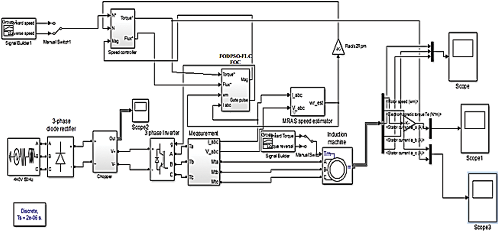
Figure 6: Simulink model of Fuzzy-FODPSO based FOC technique
This FOC system has been discretized with a step time of 2 us. To imitate the control device, the speed controller uses a 140-s period of samples whereas the DTC controller employs a 20-s sampling interval. The inverter’s switching frequency is set to 5 kHz. At time t = 0.5 s, and time t = 2 s, the reference speed is fixed to 500 rpm and the speed is lowered to 0 rpm in the forward operating mode which is shown in Fig. 7.

Figure 7: Reference speed for motor
Likewise, at time t = 1 s, the 100 Nm torque is delivered to the motor and at 2.5 s, the torque is returned to 0 Nm, as illustrated in Fig. 8. When the reference speed fixed value is raised to 500 rpm at t = 0.5 s, the motor speed accelerates and settle down at 500 rpm after 0.33 s; hence, the rotor speed and reference speed of a 3-

Figure 8: Motor shaft reference input torque
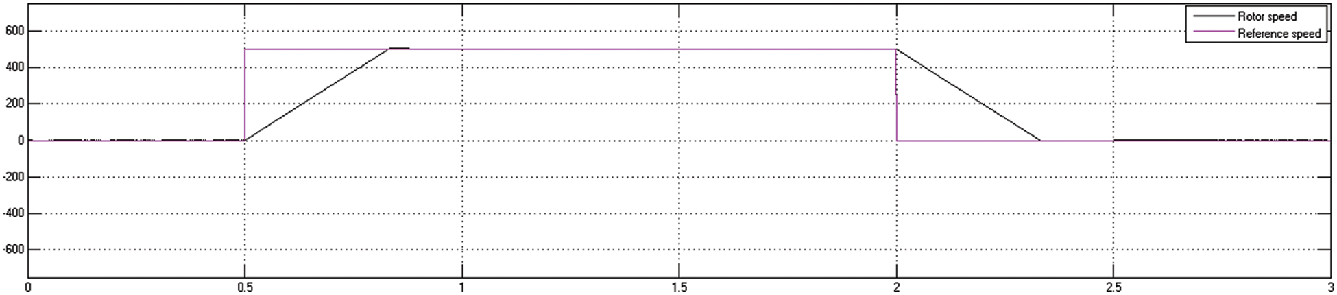
Figure 9: Motor reference speed and rotor speed using FOC method
When the motor operates, torque rises to a high value and then decreases to near zero since the motor is running with no load. As the load grows, so will the motor’s output torque to meet it. When the motor begins, the torque rises to a maximum and then decreases to near zero since the motor is running with no load. As the load rises, so will the motor’s output torque to cover it. The speed of the motor continues to increase to its end value when motor shaft receives the full load torque at t = 1 s, which is shown in Fig. 10.

Figure 10: Motor peak overshoot in the speed curve using FOC method
As the machine begins to ramp up at 0.5 s, the current’s magnitude climbs to 250 A and then decreases to 100 A at 0.85 s show in Fig. 11. The amplitude of current rises as the reference speed is increased or decelerated, but when the speed is held constant and the stator current wavers about 100 A. Fig. 12 displays a electromagnetic torque and torque reference of a three-phase IM utilising the FOC approach. The electromagnetic torque increases to 500 N.m between 0.5 s and 0.83 s. Similarly, when a load torque is delivered at 1 s, the electromagnetic torque remains constant at 120 N.m. The load torque stabilises at -400 N.m during deceleration. The electromagnetic toque oscillates approximately 110 N.m. between 2 s and 2.83 s. Fig. 13 depicts a Fuzzy-FODPSO -based DTC for a 3-
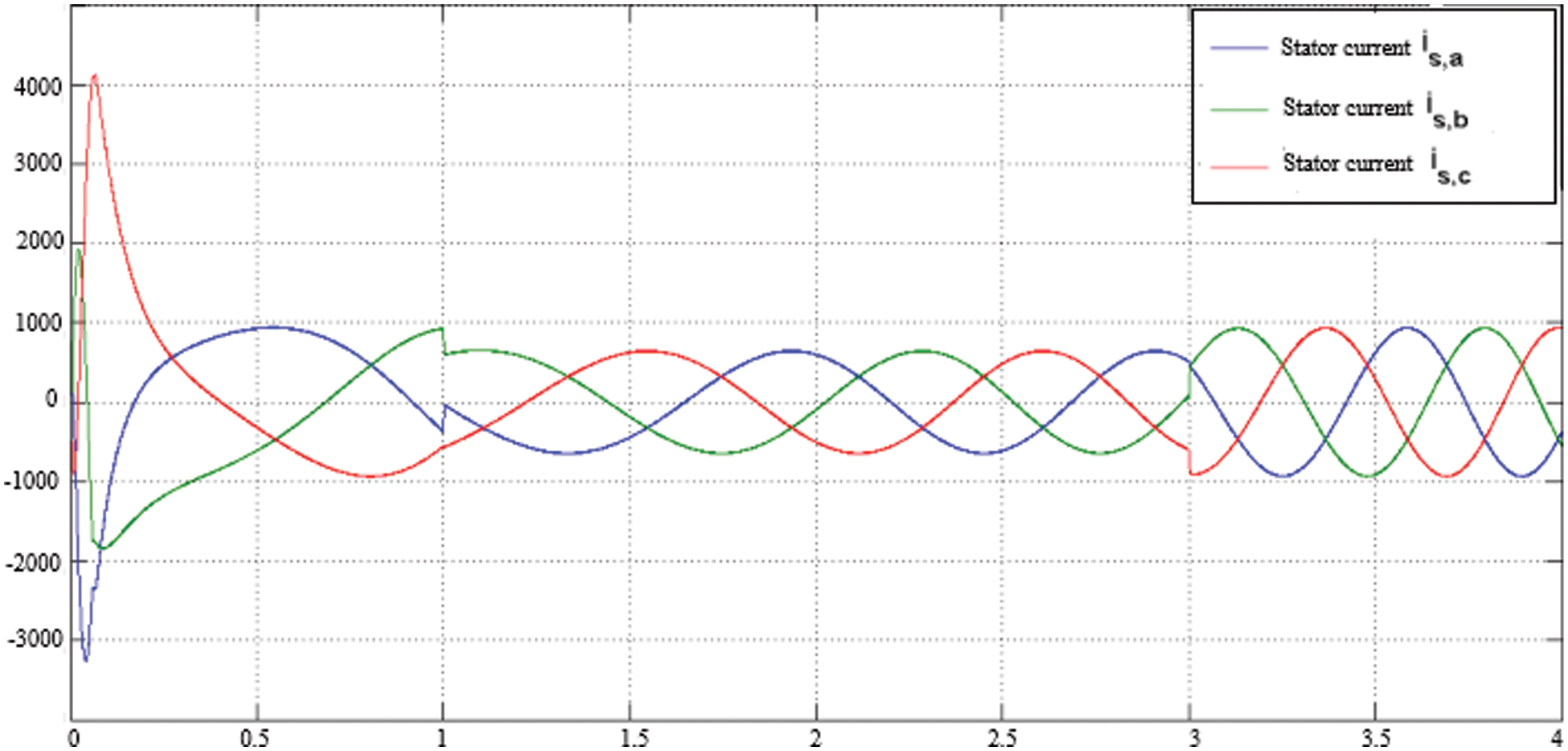
Figure 11: Motor stator current using FOC method.
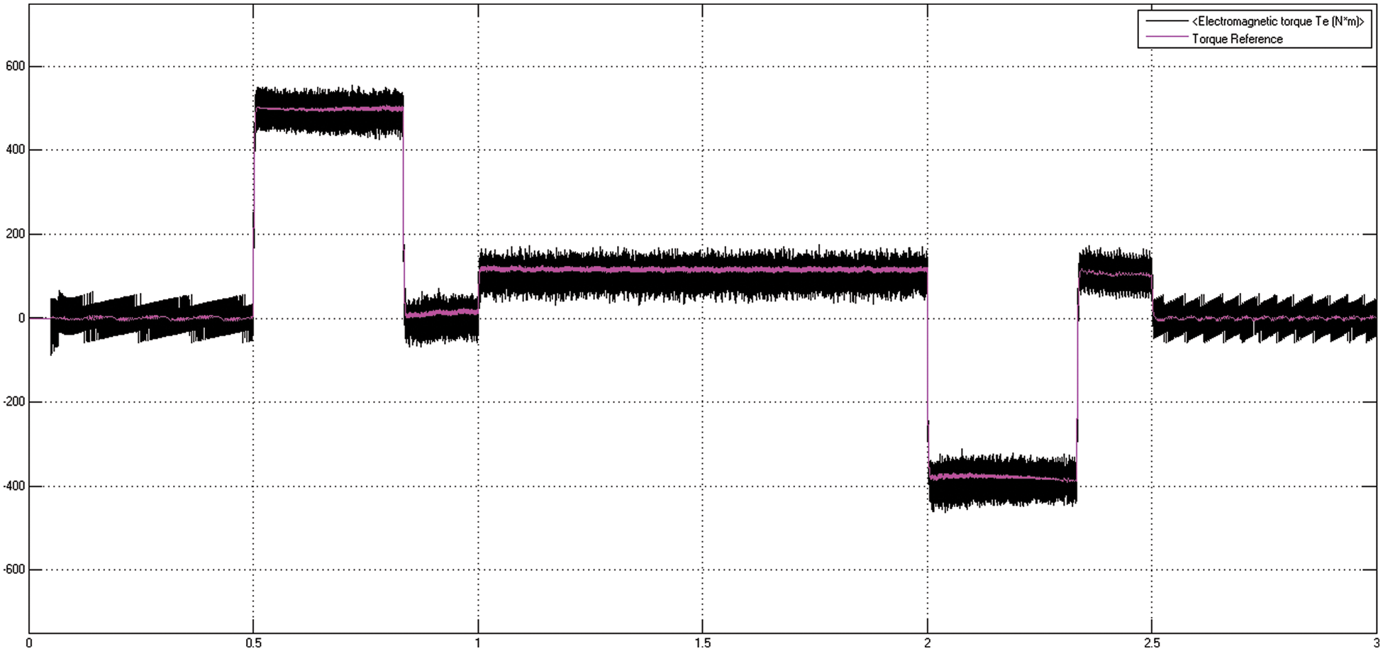
Figure 12: Motor torque reference and torque using FOC method
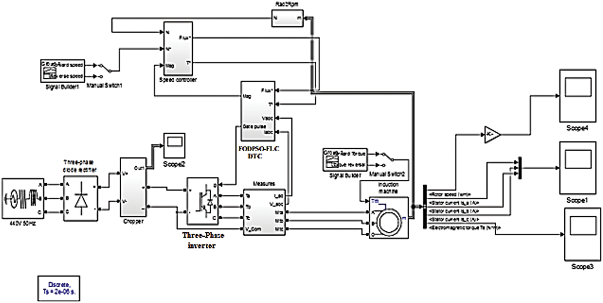
Figure 13: Simulink model of proposed Fuzzy-FODPSO based DTC technique
The stator currents are altered in accordance with the speed command. In the steady state, the torque is zero since the induction motor works at no load. The simulation results reveal that the control system has high dynamic stability and performance in various operating modes.
A 3-
The motor begins to accelerate at 0.5 s, reaching a maximum overshoot of 507 rpm at 1.05 s and settling at 500 rpm at 1.25 s. Figs. 14 and 15 demonstrate the motor’s reference rotor speed and peak overshoot by DTC technique.
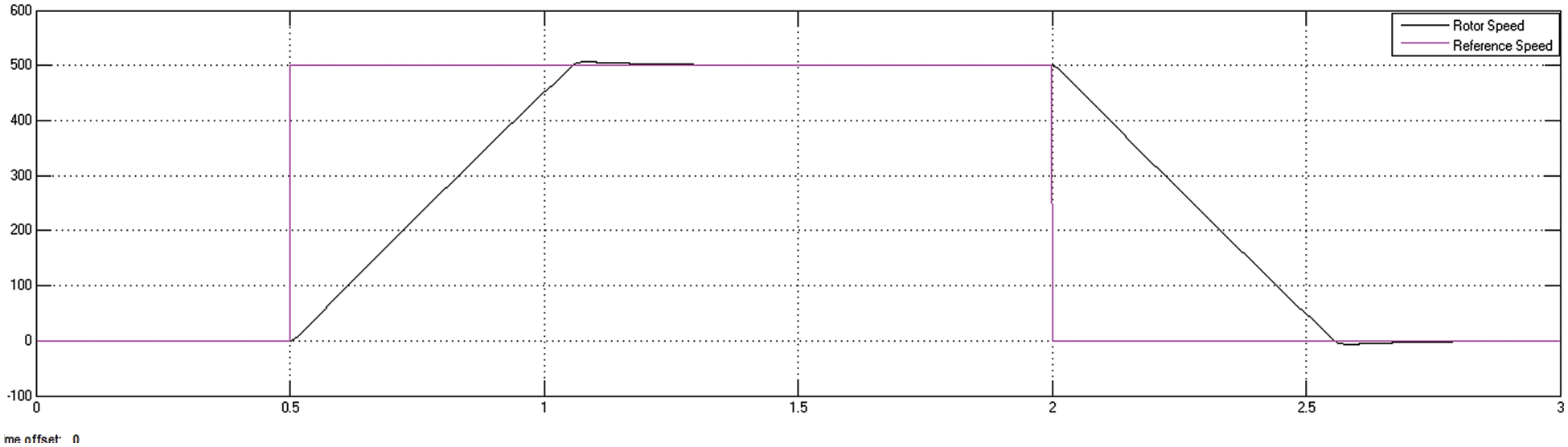
Figure 14: DTC method reference speed and rotor speed of the motor
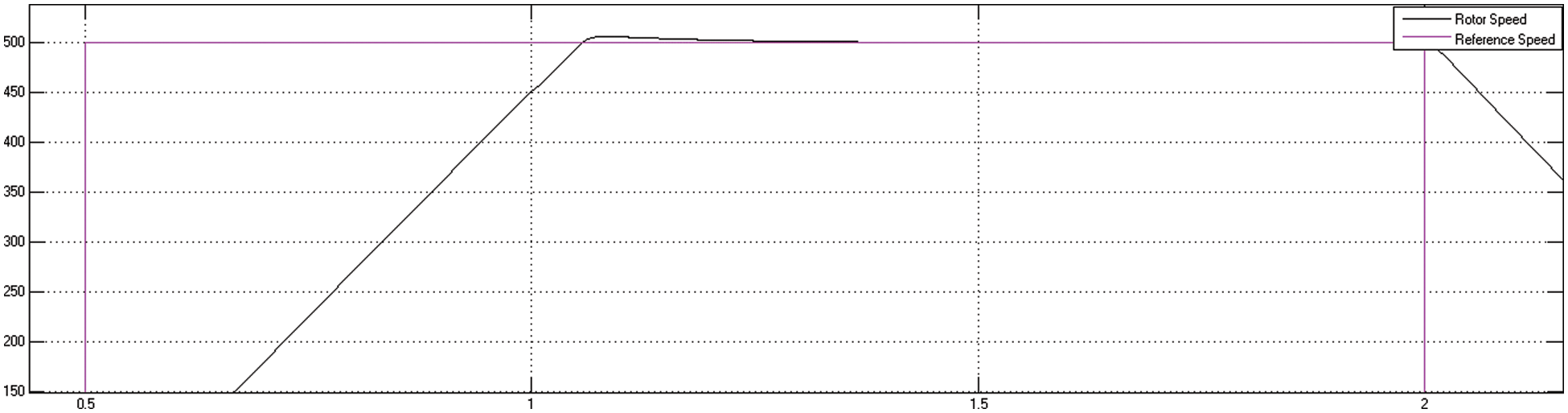
Figure 15: Motor peak overshoot using DTC method
As shown in Fig. 16, the stator starting current hikes to a negative extreme of −550 A and a positive extreme of 1080 A for a 200 HP motor, when compared to the FOC technique. The electromagnetic torque grows to a magnitude of 300 N.m during the speed acceleration at 0.5 s and settles to 100 N.m If the machine reaches a steady speed of 500 rpm, as illustrated in Fig. 17. Tab. 3 shows the proposed Fuzzy-FODPSO based DTC and FOC with conventional FOC and DTC methods performance. According to the comparison investigation, the Fuzzy-FODPSO based FOC performs improved than the others and provides effective performance across all phenomena. The Fuzzy-FODPSO speed response demonstrations that the motor drive can follow the low command speed exceptionally smoothly and quickly, with less steady-state error, overshoot, and a lower dropout speed than the fuzzy controller and Particle Swarm Optimize (PSO) – FLC in Tab. 4. The Fig. 18 shows the comparative analysis of the proposed Fuzzy-FODPSO based FOC and Fuzzy-FODPSO based DTC. From the evaluation the proposed FOC method have less steady state error, settling time, rise time and overshoot than the proposed DTC method.
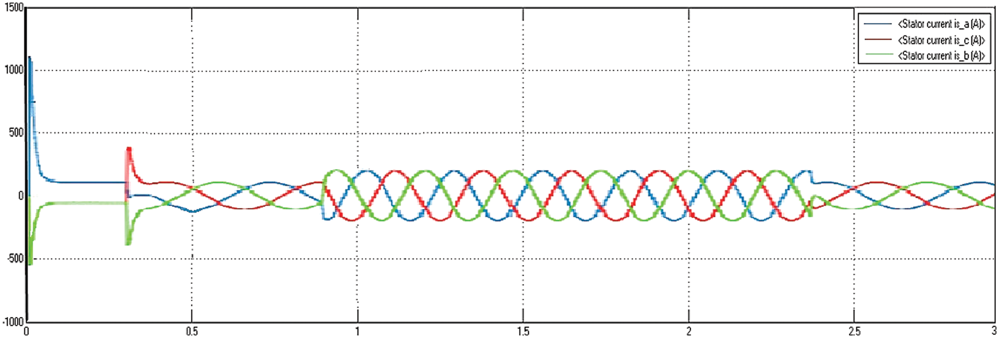
Figure 16: Motor stator current using DTC method

Figure 17: Motor torque reference and electromagnetic torque using DTC method
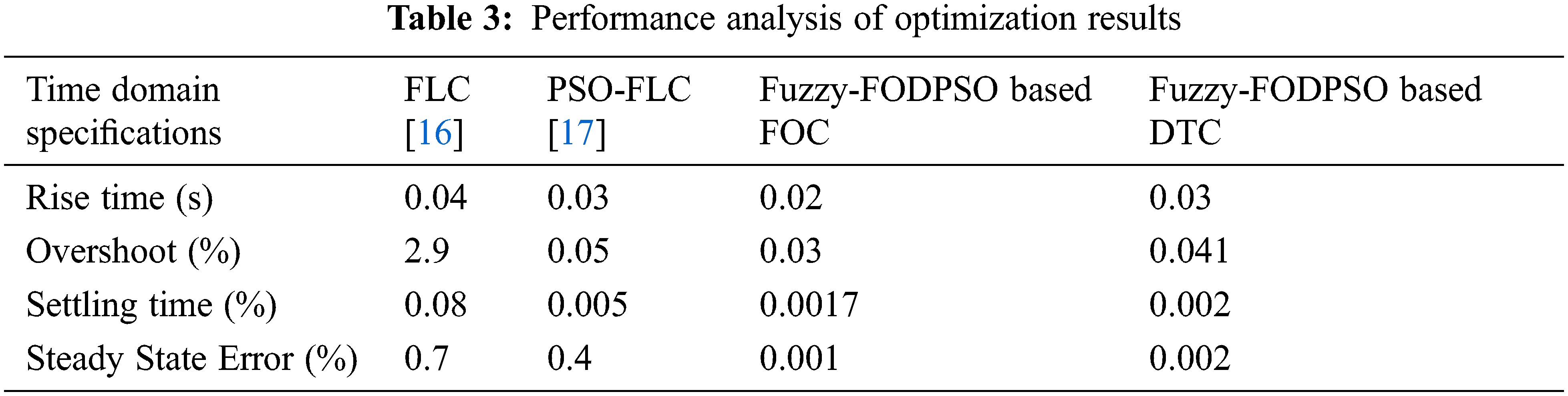
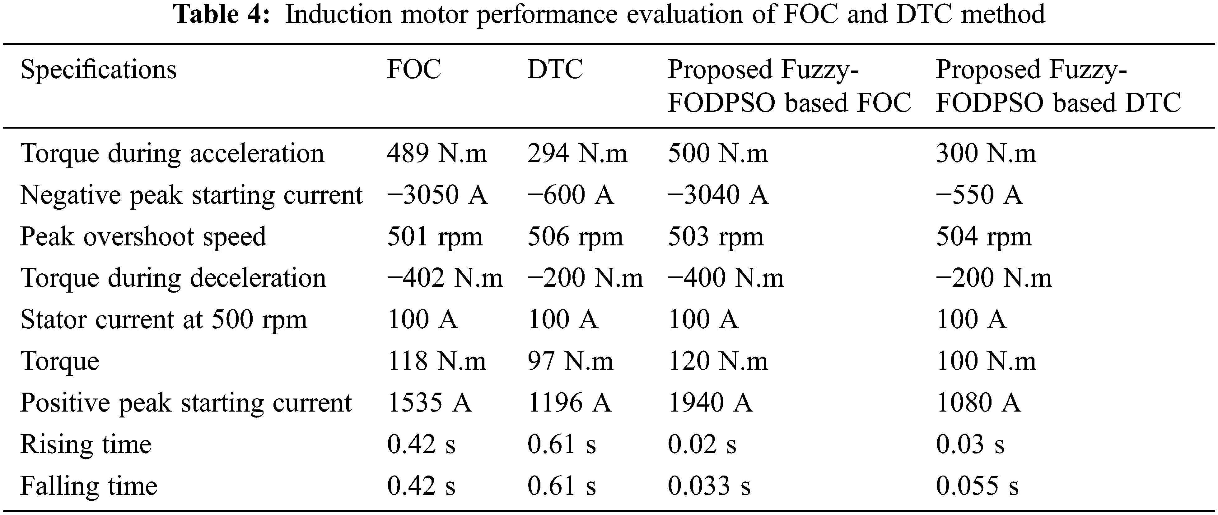
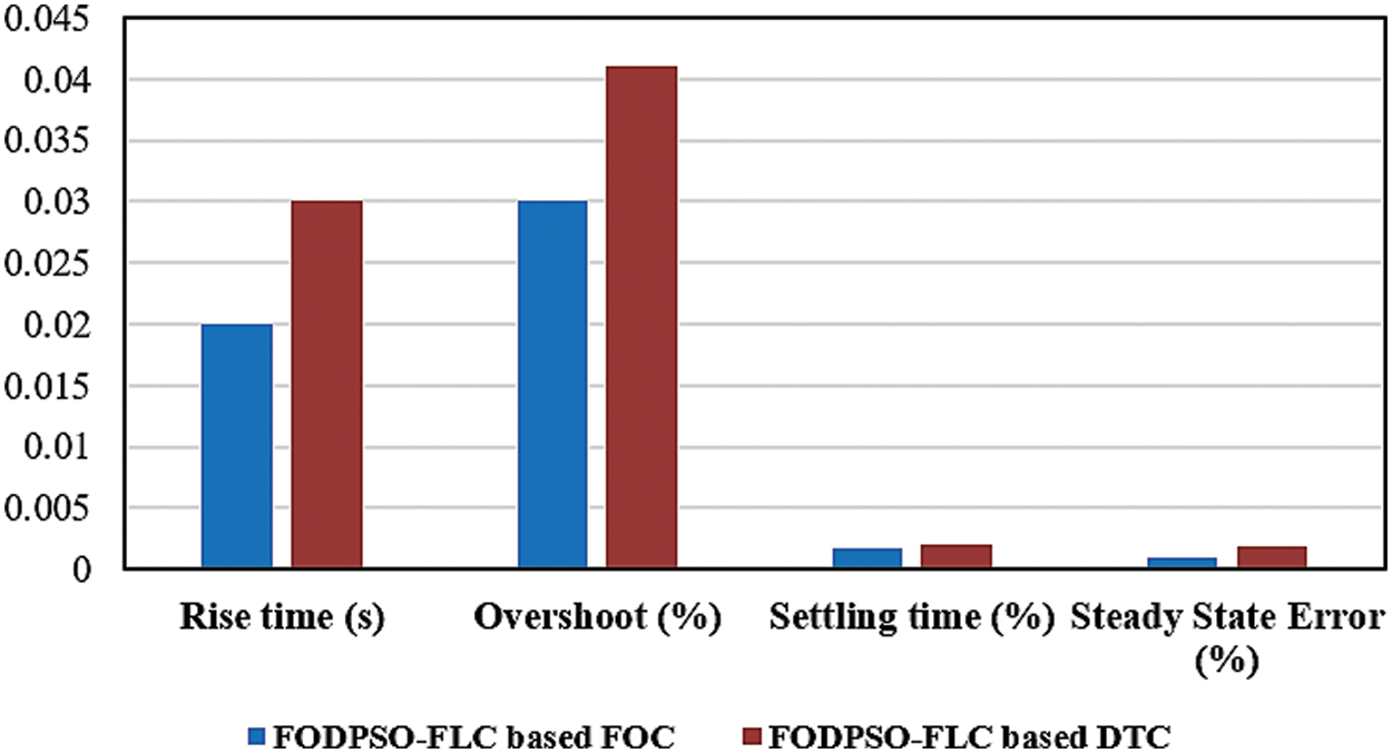
Figure 18: Performance analysis of proposed FOC and DTC method
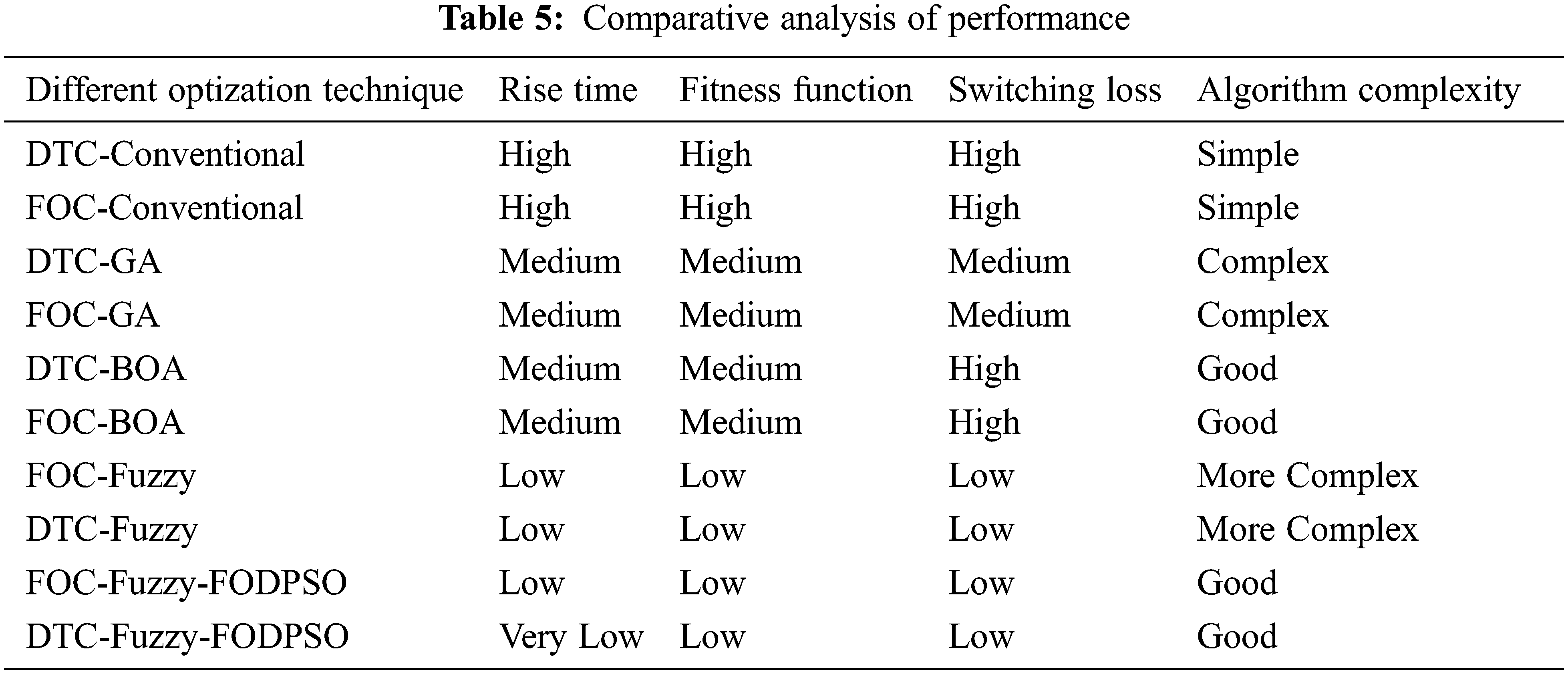
The comparative study of various optimization approaches utilised in the control of induction motor is shown in Tab. 5. It analyses several optimization techniques’ algorithm complication, switching loss, fitness function and rising time. From the above table, the proposed technique is compared with conventional DTC and FOC, genetic algorithm (GA) [20] based DTC and FOC, butterfly optimization algorithm (BOA) based DTC and FOC and fuzzy based DTC and FOC. As a consequence, the suggested FODPSO-based Fuzzy logic controlling strategy outperforms conventional optimization techniques.
7.1 Descriptions of Test Bench
The comparative control systems were put through their paces on an experimental test bench comprised of two 2.2 kW induction machines. The primary machine is powered by a 14 kVA inverter, which has complete control over the IGBT gates. The load machine serves as a load machine and is powered by a 3-kW inverter. A 1024-point incremental encoder measures the rotor position. And the electromagnetic torque is computed and measured immediately. The following Fig. 20 shows the Experiment with a drive mechanism for an induction motor.
To determine the experimental characteristics, all techniques were torque and speed examined show in Fig. 19. For fair comparisons, the same sample frequencies (16 kHz) are used, as well as relatively similar switching frequencies. Fig. 20 shows a comparative response of (a) speed and (b) torque response for FOC method for Induction Motor at (500) rpm for load torque 0 N.m. The proposed result is compared with standard DTC and GA-FOC. When the system is operated using Fuzzy-FODPSO, the results show a high responsiveness and highest ideal value.

Figure 19: Experiment with a drive mechanism for an induction motor
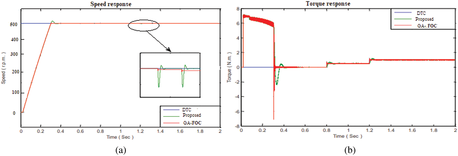
Figure 20: Comparison of (a) Speed and, (b) torque response for FOC method
According to the experimental results, conventional FOC, conventional DTC, GA-FOC, GA-DTC, and presented Fuzzy-FODPSO based FOC and Fuzzy-FODPSO based DTC all perform well. In general, FOC has a somewhat lower current THD and torque. The dynamics of DTC are rapid, but the torque ripples are greater. The proposed methodology exhibits good behaviour, with fewer torque ripples and quick dynamics. When the system is operated using Fuzzy-FODPSO, the results show a high responsiveness and highest ideal value compared to standard DTC and GA-DTC. The above Fig. 21 shows the Comparative response of (a) torque and (b) rotor response for DCT method of Induction Motor.
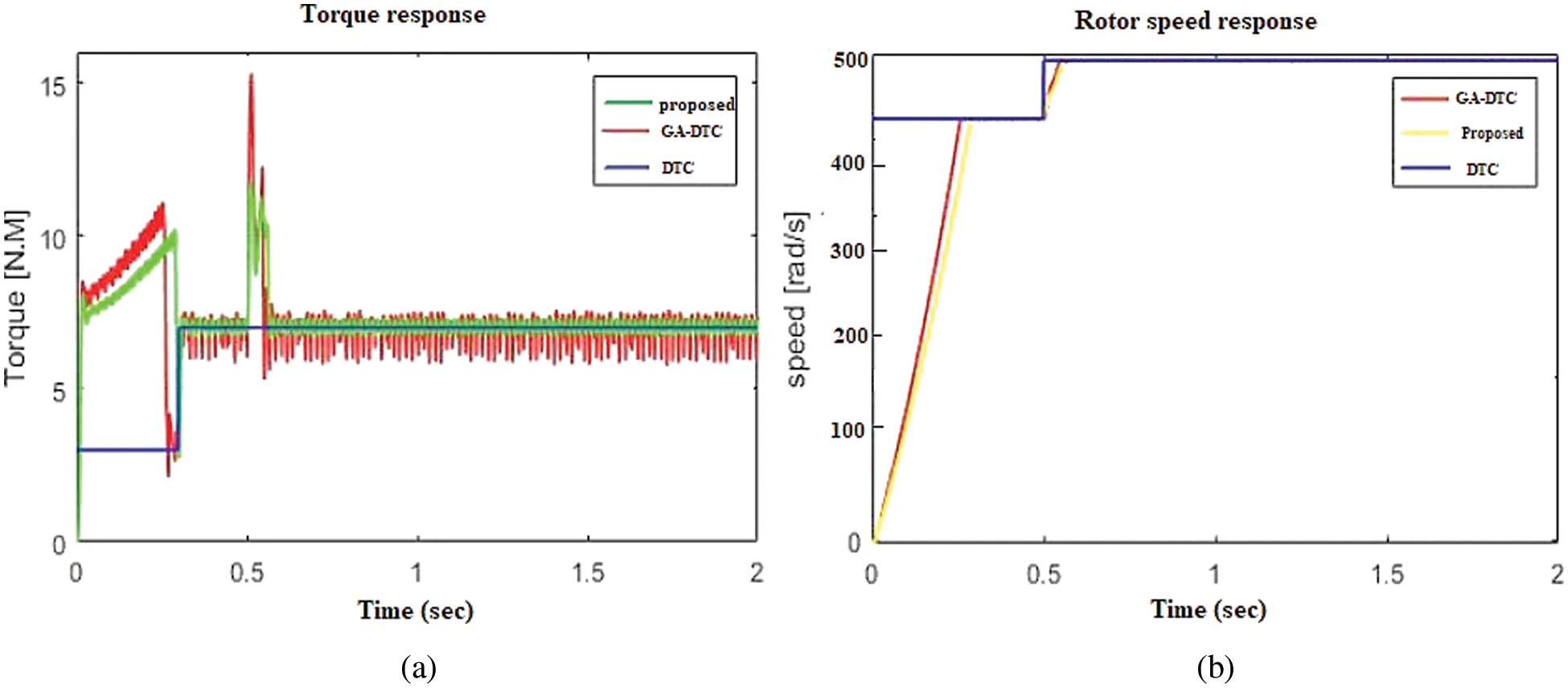
Figure 21: Comparison of (a) torque and, (b) rotor response for DTC method
MATLAB-Simulink and hardware setup was used to construct a framework of direct torque control and field-oriented control methods for a 200 HP 3-phase induction motor. It has been observed that DTC method shows improved results when compared with FOC. The optimization technique of FODPSO based Fuzzy technique is proposed to control the FOC and DTC method. The performance analyses of both the methods are carried and the outcomes are compared. The research revealed that the proposed methodology had no overshoot and short settling time than the previous methods. The FODPSO based FOC perform better than the DTC method and other conventional method. Starting current is very less in case of DTC method and the torque requirement is also less for the same speed in DTC method. Based on the results, we can infer that the technique has an intriguing use in the field of machine control system design, which will be the focus of future research in addition to the implementation of this study on a real machine.
Acknowledgement: The authors with a deep sense of gratitude would thank the supervisor for his guidance and constant support rendered during this research.
Funding Statement: The authors received no specific funding for this study.
Conflicts of Interest: The authors declare that they have no conflicts of interest to report regarding the present study.
1. T. Rekioua and D. Rekioua, “Direct torque control strategy of permanent magnet synchronous machines,” in Proc. BPTCP, Bologna, Italy, IEEE, vol. 2, pp. 6, 2003. [Google Scholar]
2. N. P. Gupta and P. Gupta, “Performance analysis of direct torque control of PMSM drive using SVPWM-inverter,” in Proc. IICPE, Delhi, India. IEEE, pp. 1–6, 2013. [Google Scholar]
3. J. Liu, F. Lin, H. Sun and T. Q. Zheng, “Optimale efficiency control of linear induction motor for linear metro,” in 2008 IEEE Power Electronics Specialists Conf., IEEE, Rhodes, Greece, pp. 673–677, 2008. [Google Scholar]
4. H. Maghfiroh, J. S. Saputro, F. Adriyanto, A. Sujono and R. L. Lambang, “Performance evaluation of fuzzy-PID in speed control of three phase induction motor,” Proc. CSMSP, IOP, Solo, Indonesia, vol. 1096, no. 1, pp. 012071, 2021. [Google Scholar]
5. M. Abassi, A. Khlaief, O. Saadaoui, A. Chaari and M. Boussak, “Performance analysis of FOC and DTC for PMSM drives using SVPWM technique,” in Proc. ICSTACCE, Monastir, Tunisia, IEEE, pp. 228–233, 2015. [Google Scholar]
6. G. K. Nisha, Z. V. Lakaparampil and S. Ushakumari, “Sensorless vector control of SVPWM inverter fed induction machine using MRAS-sliding mode,” in 2012 Int. Conf. on Green Technologies (ICGT), IEEE, Trivandrum, India, pp. 29–36, 2012. [Google Scholar]
7. B. K. Bose, “Power electronics-a technology review,” Proceedings of the IEEE, vol. 80, no. 8, pp. 1303–1334, 1992. [Google Scholar]
8. J. B. Marshel and C. K. Babulal, “Market power analysis in power systems using PSO based must run indices,” International Transactions on Electrical Energy Systems, vol. 30, no. 12, pp. e12675, 2020. [Google Scholar]
9. V. J. Bobin and M. Beno, “Performance evaluation of a PMSM with fuzzy controller employing armature voltage control scheme,” in Proc ICEETS, Tamilnadu, India, IEEE, pp. 1–8, 2018. [Google Scholar]
10. J. N. Nash, “Direct torque control, induction motor vector control without an encoder,” IEEE Transactions on Industry Applications, vol. 33, no. 2, pp. 333–341, 1997. [Google Scholar]
11. M. P. Thakre and P. S. Borse, “Analytical evaluation of FOC and DTC induction motor drives in three levels and five levels diode clamped inverter,” in 2020 Int. Conf. on Power, Energy, Control and Transmission Systems (ICPECTS), IEEE, Chennai, India, pp. 1–6, 2020. [Google Scholar]
12. S. K. Kakodia and G. Dynamina, “A Comparative Study of DFOC and IFOC for IM Drive,” in 2020 First IEEE Int. Conf. on Measurement, Instrumentation, Control and Automation (ICMICA), IEEE, Kurukshetra, India, pp. 1–5, 2020. [Google Scholar]
13. A. J. G. Malar, C. A. Kumar and A. G. Saravanan, “Iot based sustainable wind green energy for smart cites using fuzzy logic based fractional order darwinian particle swarm optimization,” Measurement, vol. 166, no. 2, pp. 108208, 2020. [Google Scholar]
14. N. E. Ouanjli, A. Derouich, A. E. Ghzizal, S. Motahhir, Chebabhi et al., “Modern improvement techniques of direct torque control for induction motor drives-a review,” Protection and Control of Modern Power Systems, vol. 4, no. 1, pp. 1–12, 2019. [Google Scholar]
15. G. Prathiba, M. Santhi and A. Ahilan, “Design and implementation of reliable flash ADC for microwave applications,” Microelectronics Reliability, vol. 88, pp. 91–97, 2018. [Google Scholar]
16. E. S. Pires, J. T. Machado, P. B. de Moura Oliveira, J. B. Cunha and L. Mendes, “Particle swarm optimization with fractional-order velocity,” Nonlinear Dynamics, vol. 61, no. 1, pp. 295–301, 2010. [Google Scholar]
17. A. Pragati, B. P. Ganthia and B. P. Panigrahi, “Genetic algorithm optimized direct torque control of mathematically modeled induction motor drive using pi and sliding mode controller,” In: Recent Advances in Power Electronics and Drives. Singapore: Springer, pp. 351–366, 2021. [Google Scholar]
18. A. Sahu, K. B. Mohanty, R. N. Mishra and D. R. Nayak, “Adaptive fuzzy sliding mode based torque and speed compensator for DTC IM drive,” in 2020 IEEE 29th Int. Symp.on Industrial Electronics (ISIE), IEEE, Delft, Netherlands, pp. 247–252, 2020. [Google Scholar]
19. G. Boukhalfa, S. Belkacem, A. Chikhi and S. Benaggoune, “Direct torque control of dual star induction motor using a fuzzy-PSO hybrid approach,” Applied Computing and Informatics, vol. 18, no. 1/2, pp. 74–89, 2020. [Google Scholar]
20. A. J. G. Malar, C. A. Kumar and A. G. Saravanan, “Iot based sustainable wind green energy for smart cites using fuzzy logic based fractional order darwinian particle swarm optimization,” Measurement, vol. 166, no. 2, pp. 108208, 2020. [Google Scholar]
21. A. H. Mutlag, H. Shareef, A. Mohamed, M. A. Hannan and J. Abd Ali, “An improved fuzzy logic controller design for PV inverters utilizing differential search optimization,” International Journal of Photoenergy, vol. 2014, no. 1, pp. 1–14, 2014. [Google Scholar]
 | This work is licensed under a Creative Commons Attribution 4.0 International License, which permits unrestricted use, distribution, and reproduction in any medium, provided the original work is properly cited. |