DOI:10.32604/iasc.2023.026211
| Intelligent Automation & Soft Computing DOI:10.32604/iasc.2023.026211 | |
| Article |
Modeling and Control of Parallel Hybrid Electric Vehicle Using Sea-Lion Optimization
1Department of EEE, St. Xavier’s Catholic College of Engineering, Chunkankadai, Anna University, Chennai, India
2St. Xavier’s Catholic College of Engineering, Chunkankadai, Anna University, Chennai, India
*Corresponding Author: J. Leon Bosco Raj. Email: boscoleon643@gmail.com
Received: 18 December 2021; Accepted: 21 February 2022
Abstract: This paper develops a parallel hybrid electric vehicle (PHEV) proportional integral controller with driving cycle. To improve fuel efficiency and reduce hazardous emissions in hybrid electric vehicles (HEVs) combine an electric motor (EM), a battery and an internal combustion engine (ICE). The electric motor assists the engine when accelerating, driving longer highways or climbing hills. This enables the use of a smaller, more efficient engine. It also makes use of the concept of regenerative braking to maximize energy efficiency. In a Hybrid Electric Vehicle (HEV), energy dissipated while braking is utilized to charge the battery. The proportional integral controller was used in this paper to analyze engine, motor performance and the New European Driving Cycle (NEDC) was used in the vehicle driving test using Matlab/Simulink. The proportional integral controllers were designed to track the desired vehicle speed and manage the vehicle’s energy flow. The Sea Lion Optimization (SLnO) methods were created to reduce fuel consumption in a parallel hybrid electric vehicle and the results were obtained for the New European Driving Cycle.
Keywords: Hybrid electric vehicle (HEV); proportional integral controller; parallel HEV; fuel efficiency; new European driving cycle (NEDC); sea lion optimization (SLnO)
Vehicle demand has risen rapidly in recent years, resulting in widespread pollution. Petrol and diesel are both expensive fossil fuels. Vehicle consumption of fossil fuels is on the rise. Transportation accounts for more than half of global energy consumption [1–4]. Energy is stored in a petroleum fuel and an electrical storage device, such as a battery pack, before being converted to mechanical energy through an internal combustion engine and electric motor [5]. HEVs are classified into three types they are parallel, series, and power-split hybrids [6–10]. HEVs challenged to integrate a mechanical engine to the electric motors, depending on mechanical controls for effective performance [11,12]. Due to their higher efficiency and lower emissions when compared to conventional vehicles, hybrid electric vehicles are increasingly acting aggressively to the current industry [13–15]. The battery supplies electricity to the electric motor, which in turn supplies power to the vehicle train, during typical operation at low speeds and cruising mode [16,17] but it also supports engine power during accelerating mode when power demand is high. As a result, both methods are combines ICE-powered vehicles’ high power density with battery-powered vehicles’ cost-effectiveness [18]. HEVs have rechargeable batteries, which provide a source of clean and green energy while reducing the demand for fuel [19–21].
The electric motor improves fuel efficiency and reduces emissions, when the ICE extends the range of the vehicle. The goal of the optimization challenge is to maximize energy efficiency between the wheel power and the battery pack, not just to maintain but also to improve its value by changing the state of charge (SOC). The optimizing simulation results demonstrate the growing efficiency when the speed set point varies, as well as the increased battery SOC. When the speed fluctuation is between 5% and 6%, the best results are produced [22]. The engine can function [23] near its ideal state practically all of the time since it is not dependent of vehicle speed and road load and the HEV control process is developed [24–29].
The major contributions of the proposed research work are listed below,
• In hybrid electric vehicles, the electric motor, battery and internal combustion engine are all combined to reduce fuel consumption.
• In the hybrid electric vehicle, electricity and fuel are energy storage units. Electricity entails the use of a battery to store energy and the use of an electromotor as a traction motor. Fuel necessitates the use of a tank, as well as the use of an Internal Combustion Engine to produce mechanical power and transform fuel to electrical energy.
• The fuel economy and emissions of vehicles has been numerically investigated using the PI controller with New European Driving Cycle under the Sea Lion Optimization.
• The performance of the system had been evaluated and the results were presented.
The highlights of the proposed research are displayed systematically as follows:
Section 1 provides an overview of the proposed work. In Section 2, a block diagram of a parallel hybrid electric vehicle is discussed. In Section 3 explains how to model a parallel hybrid electric vehicle using a PI controller and driving cycles. Section 4 explains the Sea Lion Optimization. Section 5 presents the simulation results. The paper’s conclusion is contained in Section 6.
2 Parallel Hybrid Electric Vehicle
In the parallel hybrid electric vehicle system, the coupler mechanically joins in the engine and motor output shafts are shown in Fig. 1. The internal combustion engine and an electric motor are used in the hybrid systems. In this combination have the potential to improve fuel efficiency by utilising regenerative braking on deceleration. The electric motor supplements torque to the internal combustion engine both are joined to the drive system. In the mechanical torque/speed coupler and battery are also linked to the electric motor. A transmission transmits the coupler’s output power to the wheels. Because the engine and motor drive the wheels directly, there is less energy conversion and as a consequence of low losses.
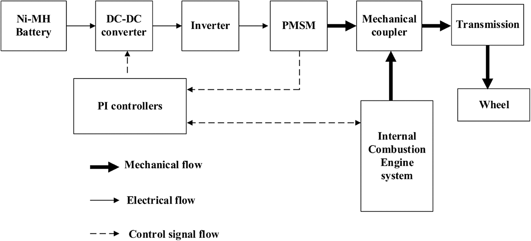
Figure 1: Block diagram of parallel hybrid electric vehicle
3 Modeling of Parallel Hybrid Electric Vehicle
As shown in Fig. 2, the HEV vehicle dynamic model is a two-axle vehicle with four equal-sized wheels that travel back and forth along the longitudinal axis. Where, β is represent the incline angle, A is specified as the effective frontal vehicle cross-sectional area, m is mentioned the vehicle mass, Vx is represent the longitudinal vehicle velocity, Fxf and Fxr are specified as longitudinal forces on the vehicle at the front and rear wheel ground contact points respectively. Fzf and Fzr are longitudinal forces on the vehicle at the front and rear wheel, Fd is the aerodynamic drag force applied to the vehicle. The tyre is a flexible body that comes into touch with the road surface and might slip.
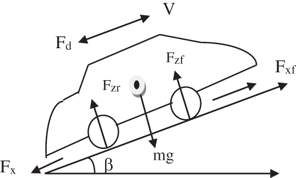
Figure 2: Forces on the vehicle
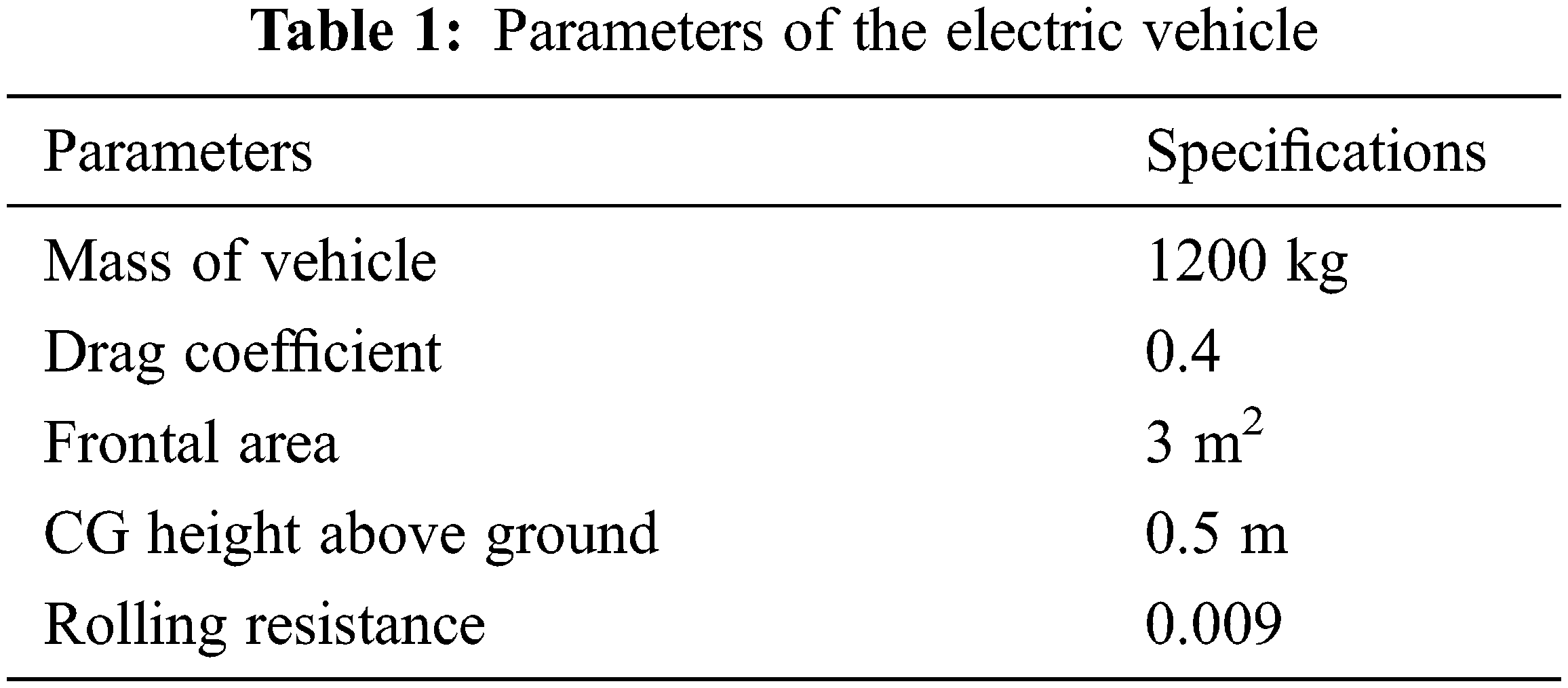
The torque is supplied to the wheel axle, the tyre deforms, pushes against the ground and finally the force is returned to the wheel, causing it to move forward or backward. The tyre model is a blend of rigid-wheel and flexible-body when it comes to the road. A tyre functions as a reliever at high speed and the longitudinal force Fx is primarily determined by the slip. The tyre behaves more like a deformable and spherical spring at low speeds, such as when starting up from or coming down from a stop. Tab. 1 shows the parameters of the electric vehicle.
In parallel, the Permanent Magnet Synchronous Motor drives the vehicle with the engine. The combined maximum output power of the motor and engine should maintain the highest value among the power requirements for maximum speed, maximum acceleration, and maximum climbing.
3.3 Internal Combustion Engine
A gasoline engine with a speed governor and spark ignition is known as an ICE model. The engine operates at a variable speed under the control of a throttle signal, which controls the output torque and so directly or indirectly adjusts the engine’s speed.
A battery is a Nickel-Metal-Hydride (NiMH) battery and the State-of-Charge is determined through using ampere-hour integration method.
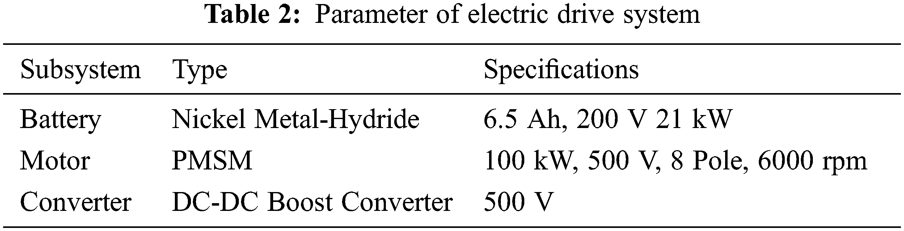
A bidirectional DC/DC converter is utilised as an electrical coupling device to boost battery voltage to 500 V, which is then maintained by a PI controller throughout charging and discharging. The relevance of the dc-dc converter, which serves as a link between the battery and the motor drive, is highlighted by its employment in battery charging and discharging circuits. The bi-directional converter allows electricity to flow from the battery to the motor during forward acceleration and conversely during braking. Tab. 2 shows the parameter of electric drive system.
The PI loops are used to independently control the variables torque and flux. To generate error signals, the measured values are compared to the reference values. The error signal is multiplied by the proportional gain Kp to generate the proportional term of the controller. The P term has the effect of lowering the overall error. The controller’s integral term calculates the error’s continuous summation. As a result, over time, a modest steady state mistake might add up to a significant error number. To generate the I term of the controller, the cumulative error is multiplied by a gain Ki. The integral term is used to reduce the small steady state errors. The outer loop is in charge of controlling the vehicle’s speed. By comparing the reference velocity to the estimated velocity, it generates an error signal. The PI controller will be designed based on the desired driving torque as well as the battery charge level. The throttle in the combustion engine is adjusted by the controller’s output. It maximises the vehicle’s output torque while reducing the internal combustion engine’s fuel consumption.
A driving cycle is a collection of data points that depict a vehicle’s speed as a function time. It is used to estimate a vehicle’s fuel consumption and vehicle’s emissions. A driving cycle is also used to measure fuel efficiency and emissions, as well as the performance of the battery, transmission, and other components, in vehicle modeling and simulation software. A New European Driving Cycle (NEDC) is a method of measuring the amount of emissions and fuel generated by car engines. The NEDC was created to simulate standard European car use. Engine and battery power are combined to increase supply during acceleration, whereas the engine is idle and the battery is recharging during braking mode.
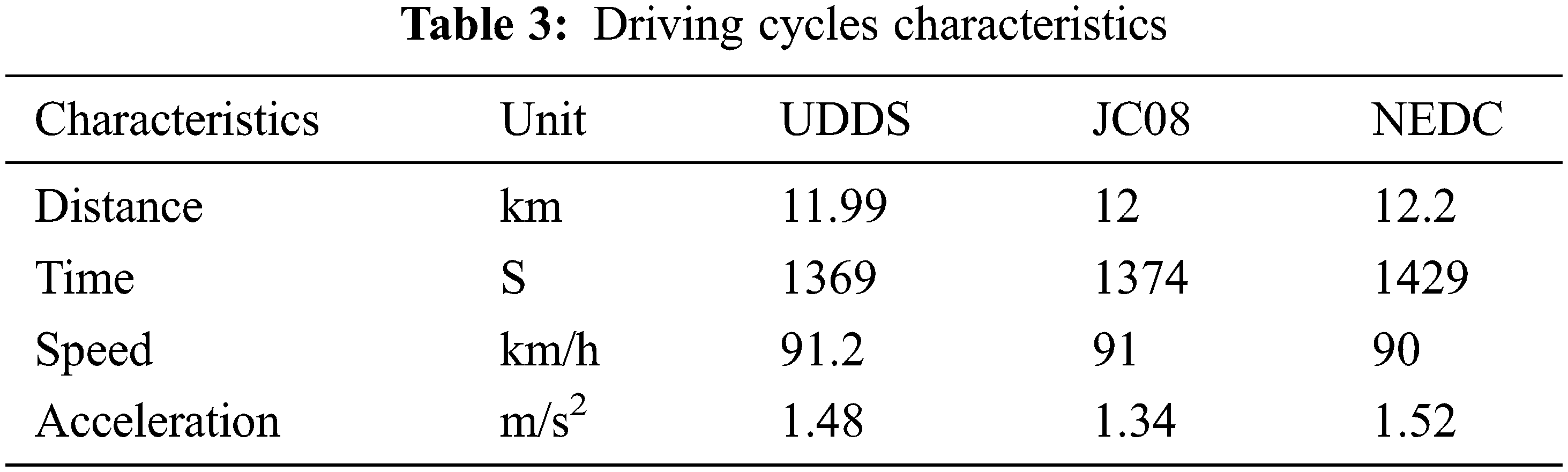
NEDC is made up of four ECE-15, UDC, and EUDC cycles that are repeated four times (EUDC). The test starts with engine and proceeds through a well-defined system for operation using exhaust gas for cyclic acceleration, braking, and composition analysis. The Urban Dynamometer Driving Schedule (UDDS) is a fuel economy test regulated by the US Environmental Protection Agency that simulates city driving conditions and is used for light duty vehicle testing. For light vehicles, the JC08 chassis dynamometer test cycle is used. The test simulates driving in crowded city traffic, including intervals of idling and frequent acceleration and deceleration. Tab. 3 shows the characteristics of the driving cycle. Unique dynamic performance and minimal emission at huge speeds are advantages of an internal combustion engine, whereas no pollution and high available power at low speeds are advantages of an electric motor drive.
The proposed model is enhanced the fuel efficiency and emission performance through optimizing the proportional gain of PI controller with NEDC driving cycle. In this paper a new optimization algorithm, is introduced to solve the optimization issues. During the algorithm search phase, avoid exceeding the engine torque operational range. Eq. (1) depicts the engine torque limited condition.
TE is represent a engine torque,
where,
4.1 Mathematical Model for SLnO Algorithm
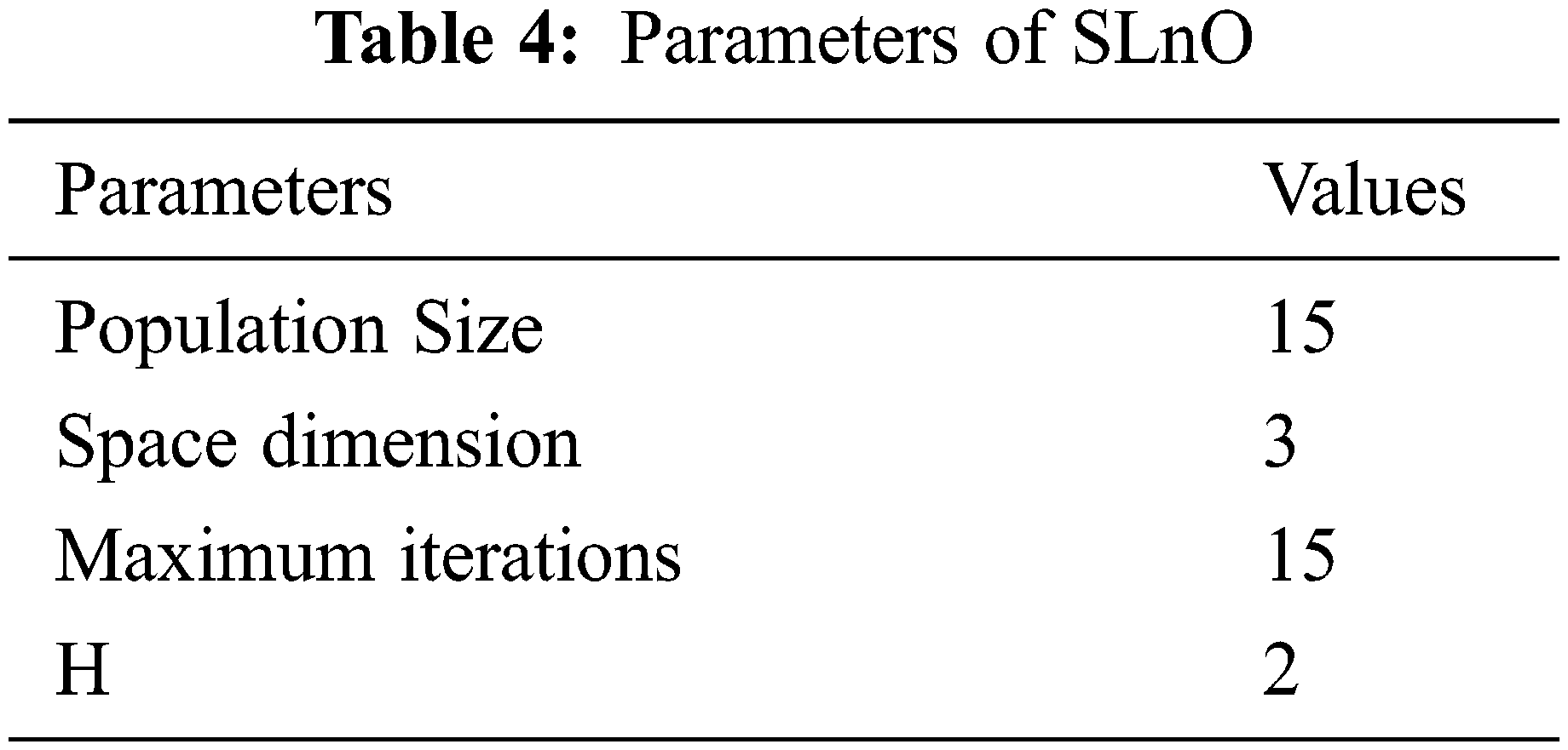
SLnO algorithm is mathematically described with four phases called tracking, social hierarchy, attacking and encircling prey. At first, initialize a random variable which is based on the population size as defined in Eq. (4).
Here the evaluation is processed under four conditions in terms of a variable ra. On the first condition, if ra is less than or equal to
4.1.1 Detecting and Tracking Phase
The sea lion’s whiskers point in the opposite direction of the sea wave, assisting the animal in feeling and recognising the approaching prey. A sea lion is the leader and other members are responsible for updating the position of the desired prey. This behaviour is mathematically defined by Eq. (5).
where,
where, (t + 1) is the next iteration H denoting the steadily decreases from 0 to 2 during an iteration.
Sea lions are capable of living on land and water. Sea lions in the water have a sound that travels four times faster than sea lions in the air. Chasing or hunting to their prey, sea lions utilise a range of vocalisations to communicate. This is mathematically computed by using Eqs. (7)–(9).
where, S leader represents the speed of the sea lion leader’s sound
P1 and P2 represent the speed of the sound in water and air.
On the second condition, if
4.1.3 Searching for Prey (Exploration Phase)
The sea lion’s location is updated based on the most effective search agent determined throughout the exploring phase. The SLnO algorithm can be described as a global search agent that analyses the global optimum solution when H is greater than 1. This is expressed in Eqs. (10) and (11) respectively.
On the third condition, if
Sea lions’ hunting behaviour is split into two sections during the exploitation phase:
Dwindling Encircling Approach:
It is considered on the value of
Circle Updating Position:
As indicated in Eq. (12), the sea lion hunts the bait ball of fishes and attacks them from the edges and the random integer l, which ranges from –1 to 1, is supplied.
The final condition is exceptional in all other cases. In this, if the
The flowchart of SLO is
A flowchart of SLnO algorithm is presented in Fig. 3. Starting with random solutions, the proposed SLnO algorithm proceeds. The optimal solution or a random search agent causes a search agent to change its location. Over the course of iterations, the parameter (S) is reduced from 2 to 0 to provide for both the exploration and the exploitation phases. When
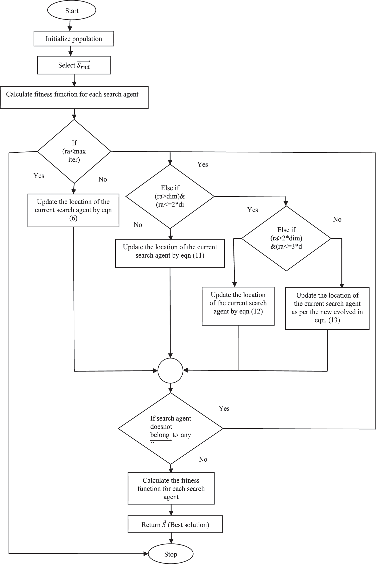
Figure 3: Flowchart of SLnO algorithm
5 Simulation Result and Discussion
The PI controller is used to mimic a parallel hybrid electric vehicle. The battery’s capacity, voltage, current, and state of charge (SOC) are all assessed. For the following drive cycle, a model is conducted in the MATLAB environment:
The cycle was designed to mimic traffic congestion in European cities. The entire loop is depicted in Fig. 4. The ECE-15 cycle, which has received EU type approval, is used to test pollution and a fuel consumption from light-duty vehicles. To manage high aggressive, high-speed driving modes, the Extra Urban Driving Cycle section was added.
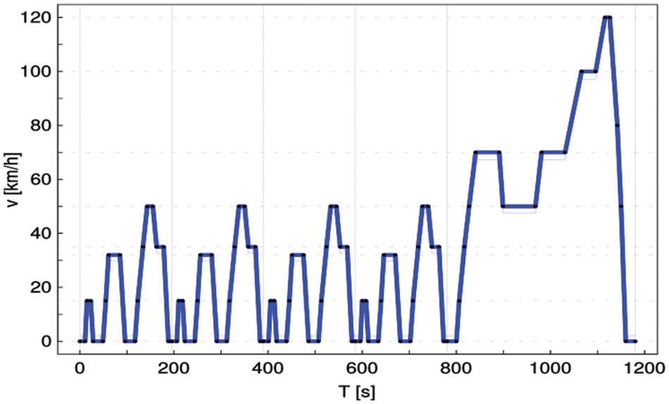
Figure 4: New European driving cycle
The motor torque is equal to the drive torque because the vehicle is only driven by engine torque. The battery powers the vehicle’s engine. As a result, during this period, motor power equals battery power, and the battery’s SOC decreases. Fig. 5 depict the accelerator signal and drive torque.
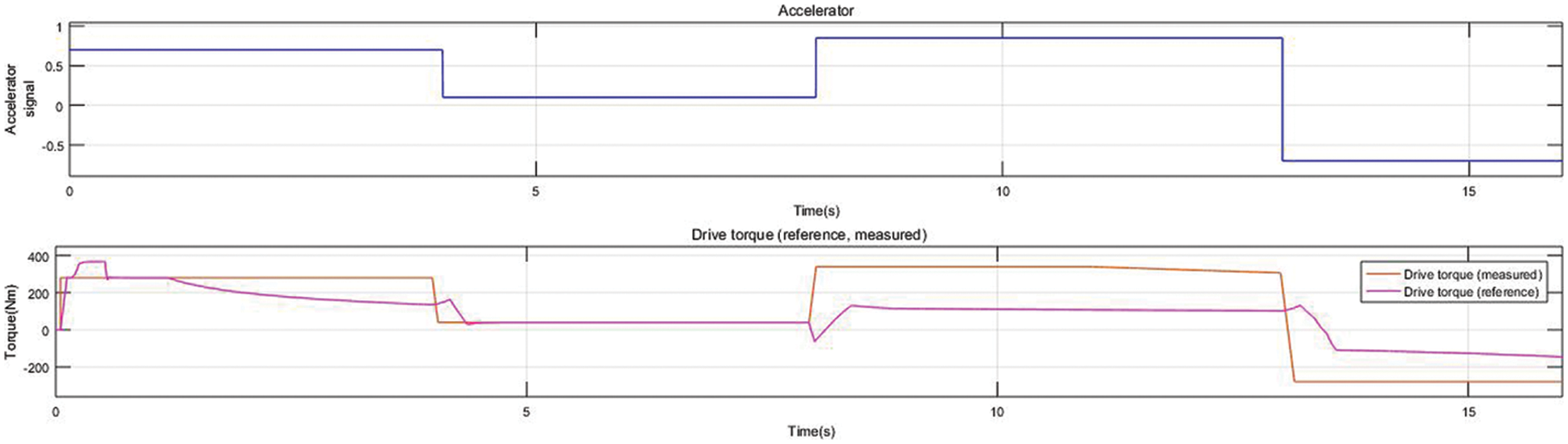
Figure 5: Accelerator signal and drive torque
The (a) DC-DC converter voltage (b) Battery and DC-bus voltage (c) Current waveforms for motor, battery (d) Soc battery are depicted in Fig. 6. The reference power exceeds the upper limit as the reference torque and speed increase (1.18 s, 4.05 s), indicating that the hybrid electric vehicle in a hybrid drive mode. Because the engine torque is positive and hybrid signal is 1. Drive torque equals motor torque because the vehicle is powered by both engine and ICE torque.
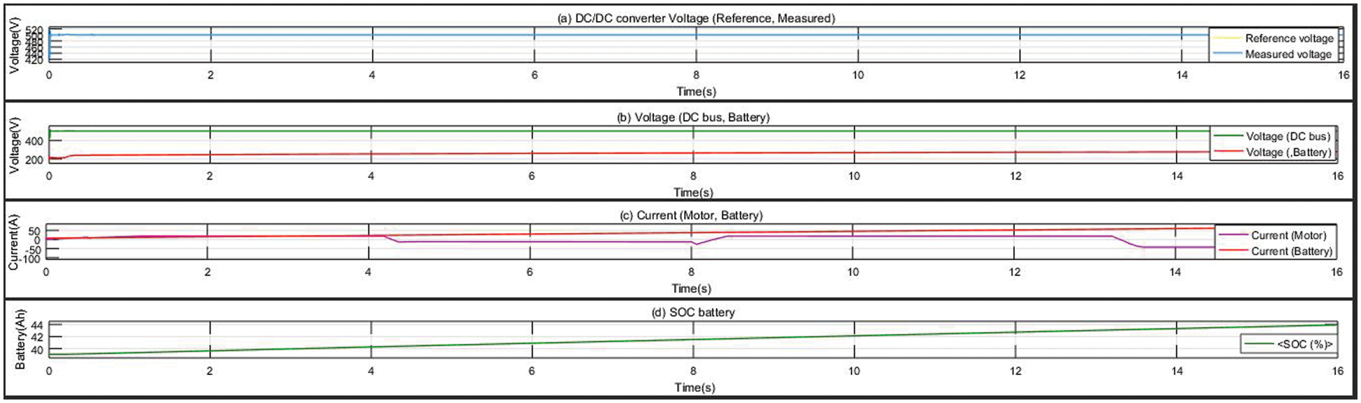
Figure 6: (a) DC-DC converter voltage (b) battery and DC-bus voltage (c) current waveforms for motor, battery (d) Soc battery
Fig. 7 shows the hybrid signal of internal combustion engine. Throughout (4.05 s, 8.01 s), the reference power is less than the upper limit, indicating that the hybrid electric vehicle is in pure electric mode: a vehicle is powered entirely the engine. On the other hand, ICE never stops producing torque all at once. ICE continues to generate torque in the process (4.05 s, 4.37 s).
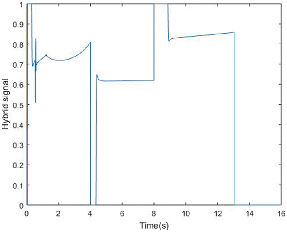
Figure 7: Hybrid signal of ICE
A HEV is still in hybrid mode throughout (4.05 s, 4.06 s), with motor torque driving an engine and battery gives the power to the engine. Power waveforms for motor, engine, battery is shown in Fig. 8. As a consequence, the engine’s torque, the motor’s power and the battery’s power are all positive. The battery’s SOC rises the motor are supplying power to the battery at this time.
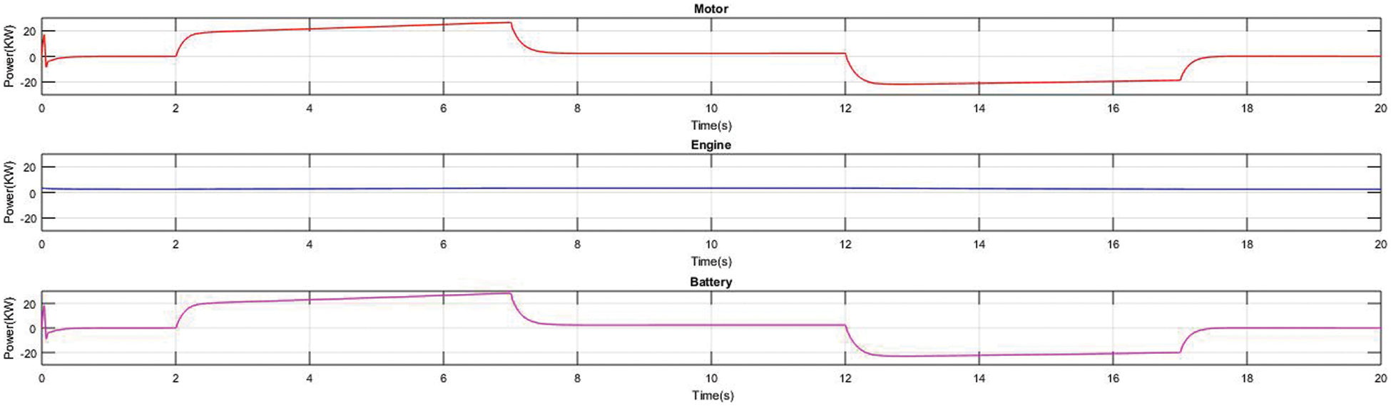
Figure 8: Power waveforms for motor, engine, battery
The vehicle is powered during operation by motor torque supplied by the battery (4.32 s, 4.37 s). Throughout, the HEV is powered by the battery powers (4.37 s, 8.01 s) the vehicle’s engine. Due to an increase in reference power, the HEV is currently in a hybrid drive mode (8.05 s, 13.08 s). Fig. 9 shows the speed waveforms. The engine is the only source of power for the HEV (8.05 s, 8.22 s). The battery powers the vehicle’s engine. Fig. 10 shows the vehicle speed.
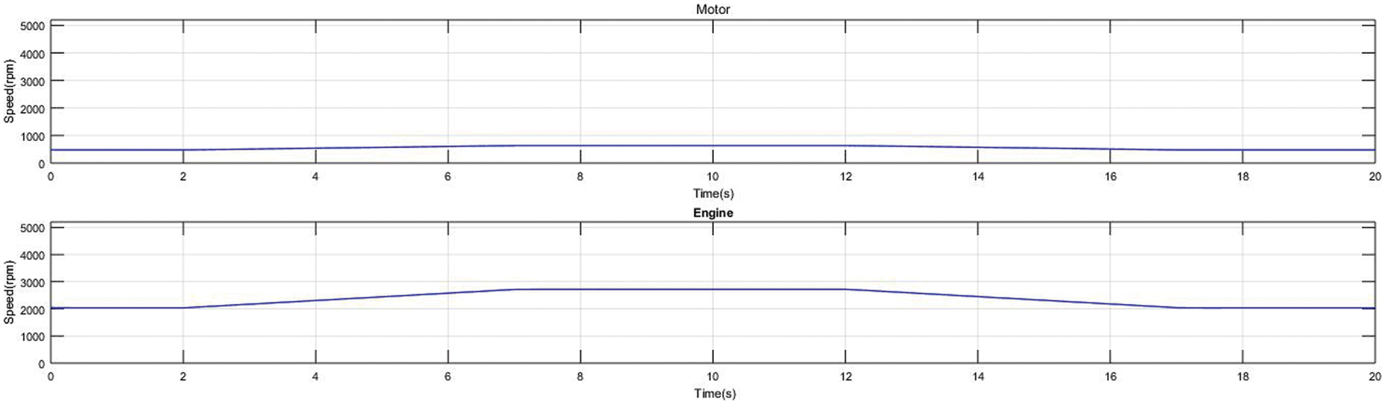
Figure 9: Speed waveforms for motor, engine
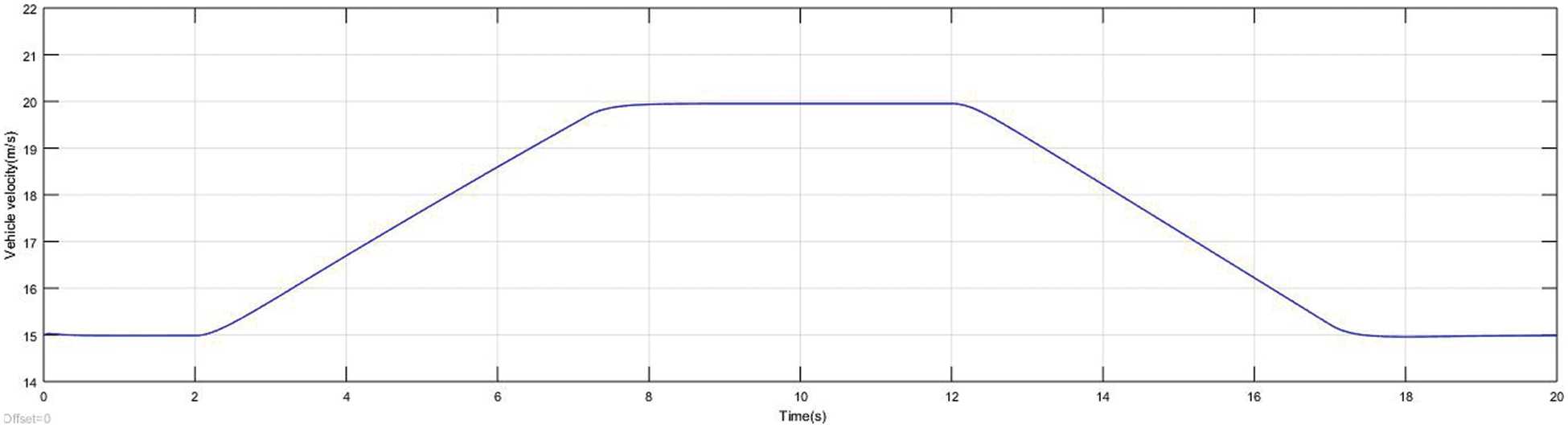
Figure 10: Vehicle speed
In a HEV, the hybrid mode for the remainder of the road (8.22 s, 10.85 s). The vehicle is carried forward by the torque produced by the battery and engine. The hybrid drive mode during (10.85 s, 13.08 s), and the engine is powered by motor torque. During this time, the battery’s state of charge (SOC) rises as a function. During (13.08 s, 16 s), both the reference power and the accelerator location signal are negative, indicating that the HEV has returned to electric mode. Since the ICE cannot stop operating all at once, the HEV, on the other hand, remains in hybrid drive mode throughout (13.08 s, 13.52 s). In the electric mode (13.52 s, 16 s), ICE is no longer operational. The car drives the engine, which charges the battery.
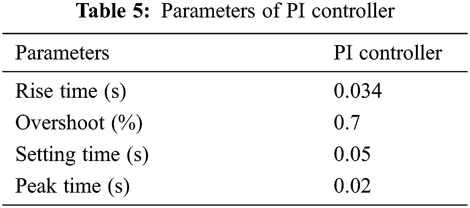
A PI controller tuning technique is applied to minimize the fuel consumption of hybrid electric vehicle. To reach the desired speed, the maximum overshoot and settling time is greatly reduced, enabling current and torque to be optimised, as well as battery operation. The optimized values of PI controller that are obtained with SLnO-PI are Kp = 0.002, Ki = 0.002. Parameter of PI controller is shown in Tab. 5.
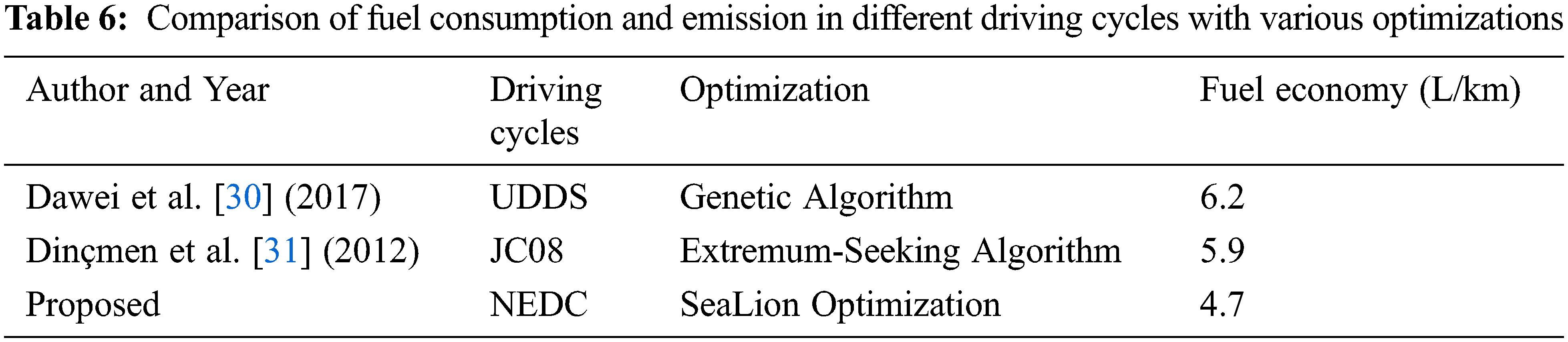
The proposed technique NEDC (New European Drive Cycle) was compared to the JC08 and the UDDS (Urban Dynamometer Driving Schedule). In NEDC cycle, the distance is 12.2, the time is 1429 s, the speed is 90 N, and the acceleration is 1.52. The relation of fuel consumption and emissions in different driving cycles with various optimizations is shown in Tab. 6. Finally, when compared to ESA and GA algorithms, the SLnO method with NEDC driving cycle is thought to generate the optimum solution while minimising fuel usage.
The parallel HEV model is build by vehicle dynamics, ICE, battery, DC/DC converter, PMSM are all included in this paper’s, which is created using Matlab/Simlunk. Simulation of PHEV under different driving cycles appears that starting of the vehicle in all the driving cycles by the motor. A power flow from the engine to the wheels is controlled using a control method that uses a parallel path. We showed that a HEV can achieve good fuel efficiency compared to a traditional vehicle with similar characteristics by more effectively using the PI controller with New European Driving Cycle under the Sea Lion Optimization.
Acknowledgement: The author with a deep sense of gratitude would thank the supervisor for his guidance and constant support rendered during this research.
Funding Statement: The authors received no specific funding for this study.
Conflicts of Interest: The authors declare that they have no conflicts of interest to report regarding the present study.
1. Y. Li, Y. Wang and X. Zhao, “Modelling and simulation study on a series-parallel hybrid electric vehicle,” World Electric Vehicle Journal, vol. 7, no. 1, pp. 133–141, 2015. [Google Scholar]
2. K. L. Butler, M. Ehsani and P. Kamath, “A matlab-based modeling and simulation package for electric and hybrid electric vehicle design,” IEEE Transactions on Vehicular Technology, vol. 48, no. 6, pp. 1770–1778, 1999. [Google Scholar]
3. D. W. Gao, C. Mi and A. Emadi, “Modeling and simulation of electric and hybrid vehicles,” Proceedings of the IEEE, vol. 95, no. 4, pp. 729–745, 2007. [Google Scholar]
4. R. Ghorbani, E. Bibeau, P. Zanetel and A. Karlis, “Modeling and simulation of a series parallel hybrid electric vehicle using REVS,” in Proc. American Control Conf., New York, NY, USA, pp. 4413–4418, 2007. [Google Scholar]
5. L. Chen, F. Zhu, M. Zhang, Y. Huo, C. Yin et al., “Design and analysis of an electrical variable transmission for a series-parallel hybrid electric vehicle,” IEEE Transactions on Vehicular Technology, vol. 60, no. 5, pp. 2354–2363, 2011. [Google Scholar]
6. O. D. Momoh and M. O. Omoigui, “An overview of hybrid electric vehicle technology,” in Proc. Vehicle Power and Propulsion Conf., Dearborn, MI, USA, pp. 1286–1292, 2009. [Google Scholar]
7. Z. Han, Z. Yuan, T. Guangyu, C. Quanshi and C. Yaobin, “Optimal energy management strategy for hybrid electric vehicles,” SAE Technical Paper, Beijing, China: Tsinghua University, 2004. [Google Scholar]
8. J. Liu and H. Peng, “Control optimization for a power-split hybrid vehicle,” in Proc. American Control Conf., Minneapolis, MN, USA, pp. 6, 2006. [Google Scholar]
9. P. Jochem, S. Babrowski and W. Fichtner, “Assessing CO2 emissions of electric vehicles in Germany in 2030,” Transportation Research Part A: Policy and Practice, vol. 78, pp. 68–83, 2015. [Google Scholar]
10. G. Rizzoni, L. Guzzella and B. M. Baumann, “Unified modeling of hybrid electric vehicle drivetrains,” IEEE/ASME Transactions on Mechatronics, vol. 4, no. 3, pp. 246–257, 1999. [Google Scholar]
11. A. Sciarretta and L. Guzzella, “Control of hybrid electric vehicles,” IEEE Control Systems Magazine, vol. 27, no. 2, pp. 60–70, 2007. [Google Scholar]
12. W. Shabbir and S. A. Evangelou, “Real-time control strategy to maximize hybrid electric vehicle powertrain efficiency,” Applied Energy, vol. 135, pp. 512–522, 2014. [Google Scholar]
13. D. W. Gao, C. Mi and A. Emadi, “Modeling and simulation of electric and hybrid vehicles,” Proceedings of the IEEE, vol. 95, no. 4, pp. 729–745, 2007. [Google Scholar]
14. T. Markel and K. Wipke, “Optimization techniques for hybrid electric vehicle analysis using advisor ASME,” International Mechanical Engineering Congress and Exposition, vol. 35548, pp. 147–155, 2001. [Google Scholar]
15. J. Wu, C. H. Zhang and N. X. Cui, “Particle swarm optimization algorithm-based parameter optimization for hybrid electric vehicle powertrain and its control strategy,” International Journal of Automotive Technology, vol. 9, no. 1, pp. 53–59, 2008. [Google Scholar]
16. Y. Li, Y. Wang and X. Zhao, “Modelling and simulation study on a series-parallel hybrid electric vehicle,” World Electric Vehicle Journal, vol. 7, no. 1, pp. 133–141, 2015. [Google Scholar]
17. D. Rizoulis, J. Burl and J. Beard, “Control strategies for a series-parallel hybrid electric vehicle,” in Proc. SAE 2001 World Congress, Detroit Michigan, United States, pp. 1354, 2001. [Google Scholar]
18. M. G. Choi and S. H. Chung, “A study on the characteristics of fuel consumption rate according to the change of acceleration patterns in EEC mode,” in Proc. Fall Conf. Proc., KSAE, Seoul, South Korea, pp. 3–8, 2004. [Google Scholar]
19. N. Robuschi, M. Salazar, N. Viscera, F. Braghin and C. H. Onder, “Minimum-fuel energy management of a hybrid electric vehicle via iterative linear programming,” IEEE Transactions on Vehicular Technology, vol. 69, no. 12, pp. 14575–14587, 2020. [Google Scholar]
20. M. E. Hmidi, I. Ben Salem and L. El Amraoui, “Analysis of rule-based parameterized control strategy for a hybrid electric vehicle,” in Proc. 2019 19th Int. Conf. on Sciences and Techniques of Automatic Control and Computer Engineering (STA), Sousse, Tunisia, pp. 112–117, 2019. [Google Scholar]
21. A. García, P. Carlucci, J. Monsalve-Serrano, A. Valletta and S. Martínez-Boggio, “Energy management strategies comparison for a parallel full hybrid electric vehicle using reactivity-controlled compression ignition combustion,” Applied Energy, vol. 272, pp. 115191, 2020. [Google Scholar]
22. J. D. Valladolid, D. Patino, G. Gruosso, C. A. Correa-Flórez and J. Vuelvas, “A novel energy-efficiency optimization approach based on driving patterns styles and experimental tests for electric vehicles,” Electronics, vol. 10, no. 10, pp. 1199, 2021. [Google Scholar]
23. J. Liu and H. Peng, “Modeling and control of a power-split hybrid vehicle,” IEEE Transactions on Control Systems Technology, vol. 16, no. 6, pp. 1242–1251, 2008. [Google Scholar]
24. M. Ehsani, Y. Gao and J. M. Miller, “Hybrid electric vehicles: Architecture and motor drives,” Proceedings of the IEEE, vol. 95, no. 4, pp. 719–728, 2007. [Google Scholar]
25. C. C. Chan, “The state of the art of electric and hybrid vehicles,” Proceedings of the IEEE, vol. 90, no. 2, pp. 247–275, 2002. [Google Scholar]
26. J. Zhang, Z. Wang, P. Liu, Z. Zhang and X. Li, “Driving cycles construction for electric vehicles considering road environment: A case study in Beijing,” Applied Energy, vol. 253, no. 1, pp. 113514, 2019. [Google Scholar]
27. M. Ehsani, Y. Gao and J. M. Miller, “Hybrid electric vehicles: Architecture and motor drives,” Proceedings of the IEEE, vol. 95, no. 4, pp. 719–728, 2007. [Google Scholar]
28. H. Yang, B. Kim, Y. Park, W. Lim and S. Cha, “Analysis of planetary gear hybrid power train system part 2: Output split system,” International Journal of Automotive Technology, vol. 10, no. 3, pp. 381–390, 2009. [Google Scholar]
29. H. M. Houyu, “Optimal design of control strategy for series hybrid electric bus,” Journal of Wuhan University of Technology, vol. 4, pp. 19, 2003. [Google Scholar]
30. M. Dawei, Z. Yu, Z. Meilan and N. Risha, “Intelligent fuzzy energy management research for a uniaxial parallel hybrid electric vehicle,” Computers & Electrical Engineering, vol. 58, no. 1, pp. 447–464, 2017. [Google Scholar]
31. E. Dinçmen and B. A. Güvenç, “A control strategy for parallel hybrid electric vehicles based on extremum seeking,” Vehicle System Dynamics, vol. 50, no. 2, pp. 199–227, 2012. [Google Scholar]
 | This work is licensed under a Creative Commons Attribution 4.0 International License, which permits unrestricted use, distribution, and reproduction in any medium, provided the original work is properly cited. |