DOI:10.32604/iasc.2023.027466
| Intelligent Automation & Soft Computing DOI:10.32604/iasc.2023.027466 | |
| Article |
Monocular Visual SLAM for Markerless Tracking Algorithm to Augmented Reality
1Shcool of Information and Intelligence Engineering, University of Sanya, 572000, Sanya, China
2Erik Jonsson School of Engineering and Computer Science, The University of Texas at Dallas, Richardson, 75080-3021, USA
*Corresponding Author: Tingting Yang. Email: ytt1202@126.com
Received: 19 January 2022; Accepted: 05 May 2022
Abstract: Augmented Reality (AR) tries to seamlessly integrate virtual content into the real world of the user. Ideally, the virtual content would behave exactly like real objects. This necessitates a correct and precise estimation of the user’s viewpoint (or that of a camera) with regard to the virtual content’s coordinate system. Therefore, the real-time establishment of 3-dimension (3D) maps in real scenes is particularly important for augmented reality technology. So in this paper, we integrate Simultaneous Localization and Mapping (SLAM) technology into augmented reality. Our research is to implement an augmented reality system without markers using the ORB-SLAM2 framework algorithm. In this paper we propose an improved method for Oriented FAST and Rotated BRIEF (ORB) feature extraction and optimized key frame selection, as well as the use of the Progressive Sample Consensus (PROSAC) algorithm for planar estimation of augmented reality implementations, thus solving the problem of increased system runtime because of the loss of large amounts of texture information in images. In this paper, we get better results by comparing experiments and data analysis. However, there are some improved methods of PROSAC algorithm which are more suitable for the detection of plane feature points.
Keywords: Markerless tracking algorithm; ORB-SLAM2 framework algorithm; augmented reality
Augmented reality is an enhanced version of the real physical world that is achieved through the use of digital visual elements, sound, or other sensory stimuli delivered via technology [1]. It is a developing trend among organizations active in mobile computing and, in particular, commercial applications. The device needs to know more for augment reality: its 3D location in the world. It calculates this based on the geographical connection between itself and a number of critical sites.
So there are several issues that must be addressed in the development and application of AR technology. For example, some AR applications need to prepare specific pictures in advance to identify the target, thus causing virtual objects to drift due to camera movement; or some AR applications based on GPS (Global Posting System) technology cannot operate in obscured scenes, resulting in poor positioning accuracy. These issues seriously affect the stability of AR applications and the user’s immersion in the virtual world, and AR technology consists of three parts: target tracking, 3D reconstruction, and virtual object rendering [2], while the real-time and stability of its applications mainly depend on the first two parts. To expand its application and robustness, domestic and foreign researchers have adapted SLAM building algorithms [3] to AR technology without previous scene layout and without relying on specific images to. As a result, SLAM has emerged as the key fundamental technique for augmented reality, which provides the ability of self-localization in the unknown location of unknown environment and mapping the 3D environment simultaneously. The localization and mapping enable the fusion of virtual objects and real-world situations geometrically consistently.
It classifies augmented reality technologies into marker-based and markerless augmented reality technologies [4] based on whether artificial markers are used to initiate the formation of virtual scenes. Although marker-based augmented reality systems can overlay real-world scenery with virtual items, this makes marker-based augmented reality applications too dependent on artificial markers for recognition, which largely limits the interaction mode of augmented reality technology and reduces the realism of virtual scenes. It is also less practical and not good for start-ups because it relies on artificial markers or unique traits. The design and implementation of marker-based augmented reality systems have been the focus and complexity of research in augmented reality. Markerless augmented reality technology will solve the issue of reliance on artificial markers and specific features. The key to markerless augmented reality technology is the augmented reality device’s location confirmation and three-dimensional space identification, and currently. SLAM is the best technical solution recognized by the augmented reality industry to achieve the effect of markerless augmented reality. Meanwhile, localization and mapping have emerged as major challenges in computer vision, and the SLAM algorithm is not only utilized in augmented reality systems, but it is also the next-generation vital technology for robotics, autonomous driving, and 3D reconstruction.
In this paper, we present an improved approach for tracking virtual objects using map information generated by visual SLAM technology. To improve the robustness of markerless tracking algorithm, in this paper we study ORB-SLAM2 [5] algorithm to locate and map, and merge AR scenes. However, there are certain issues such as texture information loss, excessive runtime, and even loss of information tracking, so we improve the uniqueness of the feature point and effectively improve the accuracy of feature matching [6]. In order to increase positioning accuracy, in this paper we add relative motion between frames as the keyframe selection criteria, and we use the PROSAC algorithm [7] to increase running speed and shorten running time.
The promise of augmented reality is that it will provide accurate, automatic, and actionable linkages between the physical world and technological information. It provides a straightforward and speedy user interface to an electronically enhanced physical world. In an ideal world, the virtual content would behave exactly like real objects. This necessitates a correct and precise estimation of the user’s viewpoint in relation to the coordinate system of the virtual content. This can be achieved by an appropriate 6-DoF tracking system. In 2002, [8] created the first AR open-source framework: AR Toolkit, laying the foundation for an augmented reality system based on template recognition. With the gradual development of feature point algorithms such as SIFT(Scale Invariant Feature Transform), SURF(Speeded Up Robust Features), and ORB, augmented reality feature matching technology has evolved into a method based on two-dimensional image feature matching, which can superimpose virtual information on any image plane with rich feature points. The augmented reality head-mounted display HoloLens glasses launched by Microsoft and the AR development platforms ARKit and ARcore launched by Apple and Google make it easier for developers to develop AR applications. Nowadays, the implementation of augmented reality technology in an unknown environment, that is, AR technology based on visual SLAM algorithm, has become a hot zone. Augmented Reality based tracking can roughly be distinguished between marker-based tracking and markerless tracking. Augmented reality technology based on marker-based tracking requires in advance preparation of a picture that can detect rich feature points and use it as a template image input system for feature extraction. In the real world, there should also be equivalent actual visuals. The camera should be adjusted to the actual image, and the feature points of the video frame and the template image should be matched. According to the matching relationship of these feature points, the position and movement of the camera in the real world can be achieved. Finally, the virtual object should be rendered to the template picture based on the information obtained by its camera and the world data.
However, there are a few disadvantages to marker-based tracking. The major restriction is that they are frequently unable to be attached to the objects which are supposed to be augmented. While this problem can be solved by using multiple cameras, it leads to a decrease in overall tracking quality and the inaccuracy of geometric registration. Furthermore, in some environments, it may consider attached mask as the noise of the image. Finally, applying markers to all locations for potential enhancement may require a lot of time and computational resources, and a lot of work for identifying information, especially in outdoor scenes. Thus, markerless tracking augmented reality technology is based on the visual SLAM algorithm, which eliminates the need for template images. The pose of the camera can be calculated directly from the device’s camera movement. At the same time, a 3D point cloud map can be built; therefore the calculation cost is high. The researchers are working to improve the accuracy of the algorithm while also maintaining its efficiency.
SLAM systems are classified as monocular SLAM, stereo-camera SLAM, and RGB-D camera SLAM according to the type of camera utilized; and we can also classify them as feature-based SLAM and direct methods according to the way they extracted feature points. The feature-based SLAM extracts feature pairs from input image feature points and descriptors, and calculates camera poses and maps by matching 2D to 2D, 2D to 3D, and 3D to 3D feature points. Visual SLAM is separated into filter-based SLAM methods and nonlinear optimization-based SLAM methods according to the method of back-end optimization [9]. The PTAM (Parallel tracking And Mapping) [10] is a typical monocular visual SLAM system based on key-frames and using nonlinear optimization. ORB-SLAM is based on the basic architecture of PTAM, and in addition to the tracking and mapping modules; a closed-loop detection module is included. In 2017, the ORB-SLAM system was enhanced with the proposed ORB-SLAM2 system, which is a full SLAM system compared to the prior ORB-SLAM system.
ORB-SLAM2 is used as the reference model of SLAM for markerless augmented reality applications. ORB-SLAM2 is a real sparse feature points SLAM system. Its central concept is to use ORB as the core feature of the complete visual SLAM. Based on the superb and comprehensive SLAM framework of the ORB-SLAM2 system, this paper optimizes it and makes it finally applicable to augmented reality applications. To improve the robustness of the algorithm and expand its scope of application, we use augmented reality as the application background and conduct the following research work:
1. To address the problem of duplicate textures in the scene leading to a high false, matching rate of the algorithm feature points, in this paper we propose an improved ORB feature point, which descriptor integrates the gray scale and gradient information of the feature point neighborhood, and combines the multi-grid strategy to capture the different granularity information of the feature point neighborhood to enhance the uniqueness of the feature point and effectively improve the accuracy of feature matching.
2. Commonly used keyframe selection algorithms first ensure that the number of internal points in the current frame exceeds a set minimum threshold and that the overlap is not too high, ensuring that keyframe tracking is directed while avoiding excessive information redundancy. To improve the positioning accuracy, this paper adds the relative motion between frames as the keyframe selection condition.
3. We have implemented the enhanced technique provided in this paper as a SLAM module in combination with an augmented reality module to build a complete markerless augmented reality system. The augmented reality module first uses the PROSAC algorithm for plane fitting, then calculates the optimal plane parameters using the point cloud information provided by the SLAM module, and finally renders the virtual model to the plane using a perspective projection transformation based on the camera poses provided by the SLAM module.
3 Framework of AR System Based on SLAM
It mainly divides the augmented reality system r into two modules in this paper: the SLAM module and the augmented reality module. The fundamental structure of the system is shown in Fig. 1. The SLAM module is divided into two parts: a front-end and a back-end. The front-end is in charge of real-time tracking of the camera and creating a local 3D map. The back-end is responsible for detecting and correcting loops in real-time, eliminating accumulated errors, optimizing global data, and allowing the system to get a globally consistent camera motion model and map model. Specifically, firstly extract the comprehensive features of points and lines in parallel from the input video frames, then calculate the initial camera pose and 3D point and line coordinates based on the matching relationship between the features of consecutive frames, and finally track the local map to look for the correspondence between the 2D features and the 3D point cloud. The relationship optimizes the camera pose and 3D point and line coordinates, and finally transmits the camera pose information and point could map information to the augmented reality module.
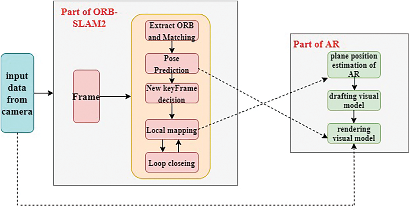
Figure 1: Framework of AR system based on SLAM
4 Coordinate System Transformation Theory of 3D Visual Model
4.1 Camera Pose Description in Three-dimensional Space
The transformations of the world coordinate system to the camera coordinate system are represented by a rotation matrix and a translation vector, which describe the rotation and translation of the camera relative to the world coordinate system, respectively. Fig. 2 is shown Oworld-XworldYworldZworld in the world coordinate system and Ocamera-XcameraYcameraZcamera in the camera coordinate system. The point P in the coordinate system is mapped to the world coordinate system as Pworld, which is mapped to the camera coordinate point as Pcamera. Therefore, the conversion relationship between the two coordinate systems can be got through the mapping relationship of the corresponding spatial points, the camera pose matrix composed of the rotation matrix R and the translation vector t, and the corresponding relationship between the point P in the two coordinate systems is formula (1), (2).
So,
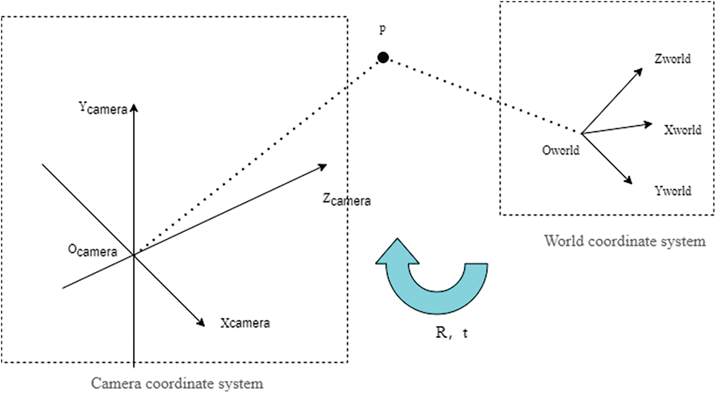
Figure 2: Conversion between camera and world
4.2 Conversion between Image and Camera Coordinates
From the camera coordinate system to the image coordinate system, it is the conversion from 3D to 2D (as shown in Fig. 3), which belongs to the perspective projection relationship. At this time, the unit of the projection point p is still mm, not the pixel, and needs to be further converted to the pixel coordinate system. If the distance from the image plane to the optical center of the camera is f, from
And according to the similarity of the triangles, the coordinates of the projection point p can be obtained;
So,
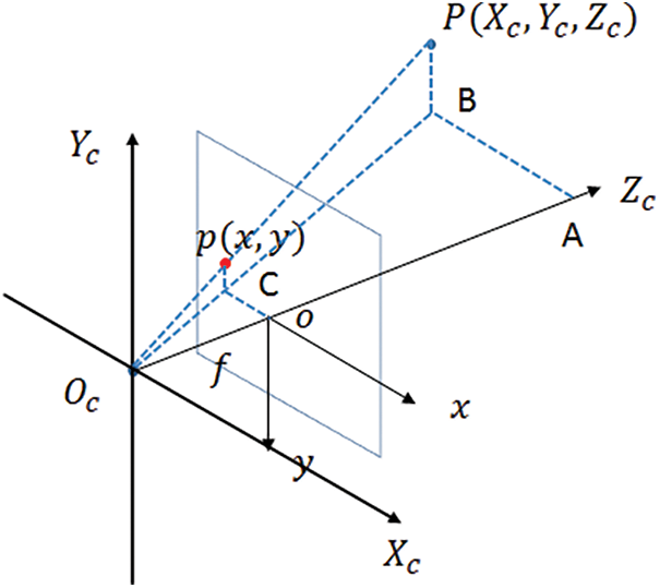
Figure 3: Converting between image and camera coordinate
4.3 Converting between Image Coordinates and Pixel Coordinates
The imaging plane contains both the prime coordinate system and the image coordinate system, but their origins and measurement units are different. The origin of the image coordinate system is the intersection of the optical axis of the camera and the imaging plane, which is usually the midpoint of the imaging plane also known as the primary point. Then in Fig. 4 image gets digitized into pixel coordinates (u, v), the coordinates of point O0 in the original image coordinate system are converted to O1 (u0, v0). In the pixel coordinate system, the physical size of the pixel is dx, dy. The unit of the image coordinate system is mm, which belongs to a physical unit, and the unit of the pixel coordinate system is pixel. We usually describe a pixel as several rows and columns. So the conversion between the two is as follows: among dx and dy represent how much each pixel represents mm, namely 1pixel = dx mm.
So,
And from the conversion of the above four coordinate systems, we can get
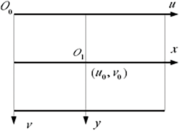
Figure 4: Converting between image and pixel coordinate
5 Designs and Improvement of ORB-SLAM2 Algorithm
5.1 System Structure of ORB-SLAM2 Algorithm
This paper conducts research based on the monocular camera mode of the ORB-SLAM2 algorithm [5]. The ORB-SLAM2 algorithm divides the system into three threads (as shown in Fig. 5) to run in parallel, namely the tracking thread, the mapping thread, and the loop detection thread. The tracking thread locates the camera in real-time, calculates the initial camera pose and map points, and then tracks the local map to get more matching relationships, the mapping thread receives the information from the tracking thread to perform local optimization and build a local map; loop detection. The testing thread detects whether the camera has been to the current location, eliminates accumulated errors, and maintains and optimizes the global map.
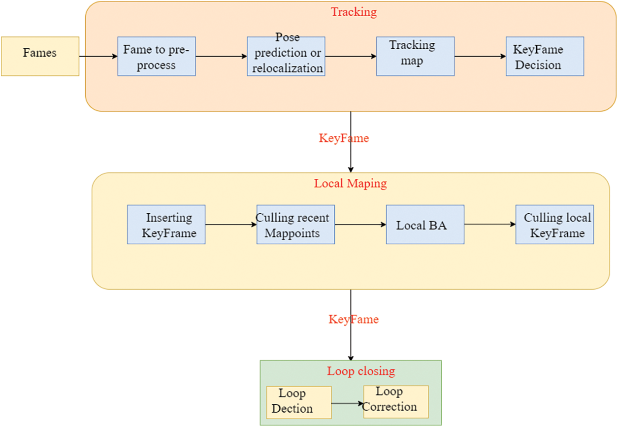
Figure 5: System of ORB-SLAM2
5.2 Improved ORB-SLAM2 Algorithms
In this section, we proposed an improved ORB-SLAM2 algorithm to address the previously noted shortcomings of ORB-SLAM2. The BRIEF(Binary Robust Independent Elementary Features) [11] descriptor used by the ORB-SLAM2 algorithm only simply considers the pixel gray information in the feature’s neighborhood point and so loses a lot of texture information. It usually requires RANSAC (Random Sample Consensus) algorithm to check the match. Increased the running time of the entire system, even in the texture repeating scene, the algorithm cannot initialize, or tracking is lost due to the high feature points mismatch rate. To improve the uniqueness of feature points and the robustness of the SLAM algorithm in texture repetitive scenes, in the feature extraction stage, a descriptor that surveys the texture information of the feature point neighborhood is used. Furthermore, the input video frames construct a Gaussian pyramid to make the feature points have to scale invariance, and then calculate the direction of the feature points, and the descriptor in their direction to ensure that the feature points haverotation invariance. The classic RANSAC method samples the point set randomly and uniformly, whereas the PROSAC method sorts the collection from the best set and avoids the use of artificial thresholds. The PROSAC algorithm is an upgraded algorithm for the classical RANSAC algorithm. The basic idea is to sort the initial set and the point set from high to low by sampling, which accelerates the calculation rate.
5.2.1 Improved ORB Feature Extraction
The BRIEF descriptor of the ORB feature solely takes into account the gray information of feature points. As a result, the feature points lack a strong sense of individuality. To better describe the feature points and extract the texture information of the image, it proposed an improved ORB feature, which is taken into account in this chapter. The descriptor comprehensively considers the gray information and gradient information of the FAST (Features from Accelerated Segment Test) corner neighborhood and then uses of multi-grid strategy to capture the multiple information of the image under different spatial granularity. They calculated the dominant direction of the corner before calculating the descriptor, and the corner neighborhood was rotated in this direction so that it has rotation invariance.
1) Construct the Gaussian pyramid for input video frames
For each input video frame
FAST corner points are extracted on each layer of the image pyramid to make it scale-invariant. In addition, each layer image of the gold tower is divided into 30 × 30 image grids, and FAST corners are extracted from each image grid to make the corner points evenly distributed.
2) Calculate the dominant direction of the FAST corner point and get the image feature descriptor
Extract FAST corner points on each layer of the image pyramid to make them scale-invariant, trim N * N image blocks centered on each corner point [12], and calculate the dominant direction of each image block based on gray-scale moments. Specifically, the gray moment of the image block is defined as mpq, and I(x, y) is the gray value of the image block,
The gray-scale centroid of the image block can be obtained by using the gray-scale moment of the image block as,
Then, the image block is rotated to the dominant direction of the feature point to calculate the tracing of the narrative gets rotation invariance. Divide the image block into n * n grid units, extract the horizontal and vertical gradients (dx, dy), and the gray value I at the center from each grid unit, and randomly extract m pairs of grids. Considering the gradient value of the grid to i, j and the gray value of the grid center, perform a binary test
Then
5.2.2 Optimize the Key Frame Selection Algorithm
The most often used keyframe selection algorithms first ensure that the number of internal points in the current frame exceeds a set minimum threshold and that the overlap is not too excessive, guaranteeing that keyframe tracking is directed while avoiding excessive information redundancy.
To improve the positioning accuracy, this paper adds the relative motion between frames as one of the keyframe selection conditions. The inter-frame relative motion reflects relative motion between frames and comprises two major components, rotation, and translation, with rotation serving as the primary change and translation serving as the secondary change [14–16], in the following flow:
Visual odometry gets matching feature points. The center-of-mass positions c0 and c0′ are calculated for both sets of points, and then the coordinates of the decenter of each point are
1) Calculate rotation matrix by optimization method as,
So R* to expand is
The sum term is defined as matrix W, then W = UEV, and E is a diagonal matrix composed of singular values, the diagonal elements are arranged from large to small, and UV is a diagonal matrix. When W is full rank, R can be calculated according to the following formula:
To calculate the translation vector t:
Then R represents the inter-frame rotation matrix between the current frame and the latest keyframe, t represents the translation vector between the two and D is obtained by R and t, and the threshold Dk is set for it in the ORB-SLAM2 system:
2) Compare the calculated relative movement with its threshold:
In the above formula, Frame key is key-frame, and Frame-cur is current-frame, then Frame-ref if reference of frame [12].When the judgment is passed, the current frame is set as a keyframe, the reference keyframe is updated at the same time, and the relative movement between the current frame and the new keyframe is calculated again.
5.2.3 Experimental Results of Feature Point Matching
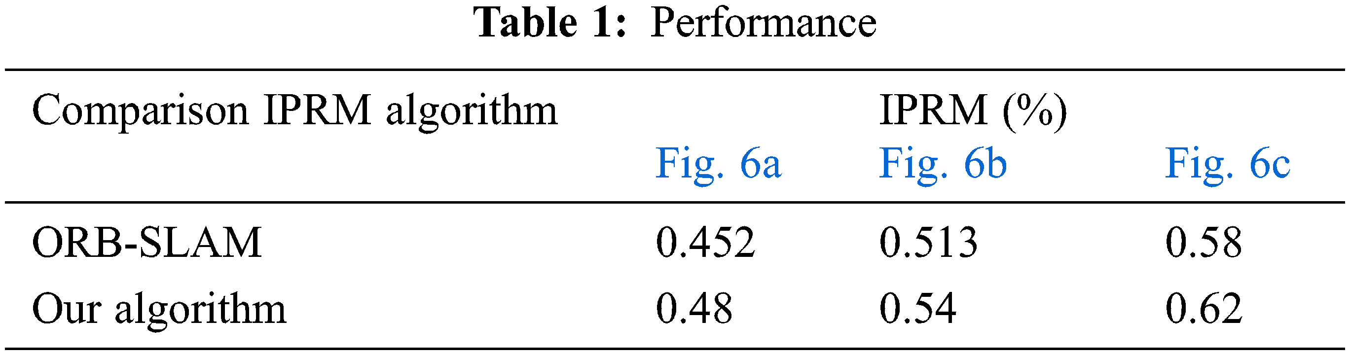
We choose the images in the TUM (Technical University of Munich) dataset for algorithm comparison. In the three image sequences (as shown in Fig. 6), we use the SLAM algorithm to calculate the interior point ratio mean (IPRM) of tracking thread point feature matching for comparison. For the experimental results see Tab. 1. It can be noticed that compared with ORB-SLAM2, the accuracy of feature points used in this chapter is higher, which is more conducive to the stable operation of the monocular SLAM algorithm.
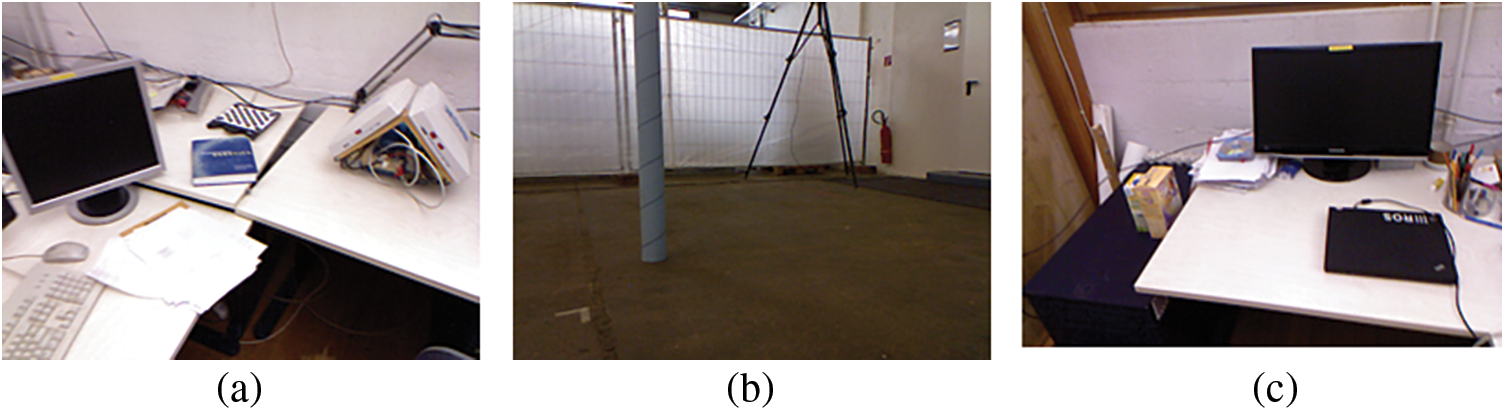
Figure 6: Images in the TUM dataset
6 Fast Real-time Plane Recognition and Detection Algorithm
If the subsequent augmented reality function is to be completed, additional perception and recognition of the real environment are required, the most crucial and basic of which is the recognition and detection of the planes in the real environment, to provide attachment points for the subsequent drawing of the virtual model, and to improve the realism of the virtual model, so that the virtual objects can be integrated into the real environment. Most of the existing unmarked augmented reality systems select the plane that can be captured in the three-dimensional space as the “ground points” of the virtual model drawn [16]. The main reason is that the recognition of the plane is relatively simple in comparison to other models. The augmented reality system has strict limitations on real-time performance and saves the overall computing time of the system.
To achieve the realism required by an augmented reality system, the virtual model shown by the augmented reality system must fit perfectly onto the plane of the real environment to which it is attached. The virtual model can then be drawn and rendered on a real-world plane. In markerless augmented reality applications, the bottom surface of the virtual model must be seamlessly on the plane of the real environment in the camera to achieve a more realistic augmented reality application.
The RANSAC algorithm estimates the parameter values of a mathematical model by iterating over noisy data by iteratively estimating the values of a mathematical model’s parameters. The underlying assumption is that the data contains non-outliers, values that can be explained by some of the model parameters, and that outliers are those data points that do not fit the model. Finally, outliers are data points that do not fit the model and are then voted out of the noise and outliers until the best target mathematical model is discovered. The algorithm is highly robust. However, the disadvantage of RANSAC algorithm is that multiple hyper-parameters need to be set artificially according to the specific problem, and there is no upper constraint of time, which means it will not converge naturally and can only be limited by the maximum number of iterations.
So we adopt PROSAC algorithm to optimize the plane recognition algorithm. The structure of the PROSAC (as shown in Fig. 7) algorithm is similar to RANSAC. To begin, hypotheses are generated by random sampling. Unlike in RANSAC, the samples are not drawn from all data, but from a subset of the data with the highest quality. The hypothesis generation set’s size is steadily expanded. The samples that are more likely to be uncontaminated are examined early. PROSAC is designed to generate the same samples as RANSAC, but in a different order. The hypotheses are verified against all data. The PROSAC algorithm is based on the principle that data points with high similarity are more likely to be interior points of the algorithm output. Therefore, semi-random PROSAC will not be less efficient than the fully random RANSAC algorithm in the worst-case scenario.
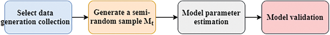
Figure 7: Framework of PEOSAC algorithm
Let the sampled data set be M and the evaluation function be q. The smallest evaluation function value of all elements in M is the evaluation function of the sampled set as,
And Tn is the average number of elements
7 Implementation Experiment of Augmented Reality System Based on SLAM
7.1 Enhancing the Interaction between Reality Module and SLAM Algorithm
The interaction between the augmented reality module and the SLAM algorithm is shown in Fig. 1. When the plane is not found in the SLAM system, the initial pose of the model is set to T0, and the SLAM system transmits the current frame pose and the current frame image data to the AR module; when the plane is found in the SLAM system, the pose of the model is set to Tpw, and the SLAM system still transmits the current frame pose and the current frame image data to the AR module [17–19]. A buffered Blocking queue severs as the transmission container between the SLAM system and the augmented reality module. The buffered blocking queue is a mutually exclusive operation to that ensures no dirty data, wrong data, or other undesirable data is generated; and the blocking queue has a fixed length L, beyond which the data will be automatically overflowed, the rendering module will lose some image frame data.
7.2 System Performance Analysis
The operation effect of the augmented reality system constructed in this paper in the actual scene is displayed and analyzed respectively on the SLAM module and the augmented reality module, and finally, the practicability of the system in this paper is evaluated. In the experimental environment that the system runs in Ubuntu 16.04, the processor is Intel Core i5-6530 M, the graphics card is NVIDIA 1660TI, the memory is 8 G, the main frequency is 3.0 GHz, and the camera resolution is 640 * 480.
The SLAM module of the system handles real-time estimation of the camera pose and the current frames’ ambient point cloud map, while the augmented reality module detects the best plane in the scene and renders the virtual model. The system will draw the virtual model represented in the real world in real-time, as seen in Fig. 8. Among them, Fig. 8a shows that the SLAM module extracts the feature points in the environment for initialization; Fig. 8b displays the best plane fitted by the augmented reality module in the current scene, and Fig. 8c shows the rendering in different perspectives.
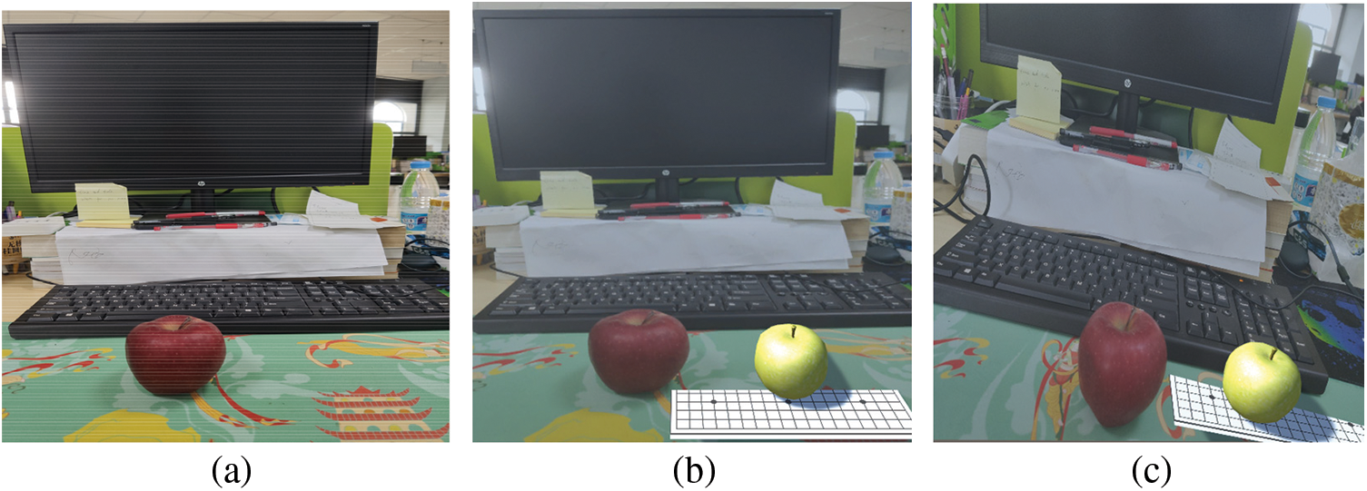
Figure 8: System of running effect. The SLAM module extracts the feature points in the environment for initialization (a), and the best plane fitted by the augmented reality module in the current scene (b), and the rendering in different perspectives (c)
In recent years, augmented reality technology has gradually entered people’s production life, from high-end laboratories to the ability to superimpose information in the real world anytime and anywhere. Augmented reality provides a new type of human-computer interaction with realistic effects, diverse forms, and low cost. However, the practical application of augmented reality is still not mature enough, and factors such as environment type and camera movement speed can have an impact on its effect and stability. We found that SLAM technology is highly adaptable for use in augmented reality. Augmented reality requires accurate camera posture estimation and 3D real-time reconstruction of the scene, and SLAM plays a role in augmented reality. A good augmented reality experience necessitates SLAM systems capable of handling a variety of complex camera motions to enhance the user experience [17]. In this paper we evaluate the existing feature matching-based SLAM algorithm standard framework ORB-SLAM2, modify it to overcome its shortcomings, and eventually build an augmented reality system based on the ORB algorithm and adopt PROSAC algorithm. Although in this paper we optimized the approach for various situations, there are still some research possibilities that can be pushed. For example, the feature matching-based visual SLAM algorithm needs to continuously compute a large feature, which makes it unsuitable for use on devices with limited hardware capabilities. It also frequently requires GPU acceleration, but in augmented reality systems, the function of the GPU is to render models [20]. The plane detection algorithm is improved by PROSAC algorithm, and the experiment process feature point cloud is reduced, but it is still necessary to design a more rapid sparse point cloud-based fast plane recognition detection algorithm.
Funding Statement: This work is supported by the Hainan Provincial Natural Science Foundation of China (project number: 621QN269) and the Sanya Science and Information Bureau Foundation (project number: 2021GXYL251).
Conflicts of Interest: The authors declare that they have no conflicts of interest to report regarding the present study.
1. R. T. Azuma, “A survey of augmented reality,” Presence: Teleoperators and Virtual Environments, vol. 6, no. 4, pp. 355–385, 1997. [Google Scholar]
2. D. Schmalstieg and T. Höllerer, “Tracking,” in Augmented Reality Principles and Practice, 1st ed., Boston, USA: Addison-Wesley Press, pp. 140–145, 2016. [Google Scholar]
3. T. Bailey and H. Durrant-Whyte, “Simultaneous localization and mapping (SLAMPart ii,” IEEE Robotics Automation Magazine, vol. 13, no. 3, pp. 108–117, 2006. [Google Scholar]
4. P. Q. Brito and J. Stoyanova, “Marker versus markerless augmented reality. Which has more impact on users?,” International Journal of Human Computer Interaction, vol. 11, no. 3, pp. 1–15, 2017. [Google Scholar]
5. R. Mur-Artal and J. D. Tardos, “ORB-SLAM2: An open-source SLAM system for monocular, stereo, and RGB-D Cameras,” IEEE Transactions on Robotics, vol. 33, no. 5, pp. 1–8, 2017. [Google Scholar]
6. S. Lee, “A study on classification and detection of small moths using cnn model,” Computers, Materials & Continua, vol. 71, no. 1, pp. 1987–1998, 2022. [Google Scholar]
7. O. Chum and J. Matas, “Matching with PROSAC–progressive sample consensus,” in Proc. Conf. on Computer Vision and Pattern Recognition, San Diego, USA, pp. 1–7, 2005. [Google Scholar]
8. H. Kato, “ARToolKit: Library for vision-based augmented reality,” Technical Report of Ieice Prmu, vol. 101, no. 625, pp. 79–86, 2002. [Google Scholar]
9. S. M. Mostafa, “Clustering algorithms: Taxonomy, comparison, and empirical analysis in 2D datasets,” Journal on Artificial Intelligence, vol. 2, no. 4, pp. 189–215, 2020. [Google Scholar]
10. K. Georg and M. David, “Parallel tracking and mapping for small AR workspaces,” in Proc. Int. Syamp. on Mixed and Augmented Reality, Nara, Japan, pp. 1–10, 2007. [Google Scholar]
11. M. Calonder, V. Lepetit, C. Strecha and P. Fua, “BRIEF: Binary robust independent elementary features,” in Proc. European Conf. on Computer Vision, Hersonissos, Greece, pp. 778–792, 2010. [Google Scholar]
12. J. C. Piao and S. D. Kim, “Adaptive monocular visual-inertial SLAM for real-time augmented reality applications in mobile devices,” Sensor, vol. 17, no. 2567, pp. 1–25, 2017. [Google Scholar]
13. X. R. Zhang, W. F. Zhang, W. Sun, X. M. Sun and S. K. Jha, “A robust 3-D medical watermarking based on wavelet transform for data protection,” Computer Systems Science & Engineering, vol. 41, no. 3, pp. 1043–1056, 2022. [Google Scholar]
14. J. Carmigniani, B. Furht, M. Anisetti, P. Ceravolo, E. Damini et al., “Augmented reality technologies, systems and applications,” Multimedia Tools and Applications, vol. 51, no. 1, pp. 341–377, 2011. [Google Scholar]
15. Y. Wang, S. Zhang, S. Yang, W. He and X. Bai, “Mechanical assembly assistance using marker-less augmented reality system,” Assembly Automation, vol. 38, no. 1, pp. 77–87, 2018. [Google Scholar]
16. X. R. Zhang, X. Sun, X. M. Sun, W. Sunand and S. K. Jha, “Robust reversible audio watermarking scheme for telemedicine and privacy protection,” Computers, Materials & Continua, vol. 71, no. 2, pp. 3035–3050, 2022. [Google Scholar]
17. S. Y. Moon, S. Y. Yun, H. S. Kim and L. S. Kang, “Improved method for increasing maintenance efficiency of construction structure using augmented reality by marker-less method,” Journal of the Korean Society of Civil Engineers, vol. 35, no. 4, pp. 961–968, 2015. [Google Scholar]
18. M. Z. Cheng, L. Y. Zhang and L. Liu, “An augmented reality image registration method based on improved ORB,” Journal of Physics: Conference Series, vol. 1554, no. 1, pp. 1–10, 2020. [Google Scholar]
19. S. M. Mostafa, “Clustering algorithms: Taxonomy, comparison, and empirical analysis in 2D datasets,” Journal on Artificial Intelligence, vol. 2, no. 4, pp. 189–215, 2020. [Google Scholar]
20. S. Mishra and M. Prakash, “Digital mammogram inferenceing system using intuitionistic fuzzy theory,” Computer Systems Science and Engineering, vol. 41, no. 3, pp. 1099–1115, 2022. [Google Scholar]
 | This work is licensed under a Creative Commons Attribution 4.0 International License, which permits unrestricted use, distribution, and reproduction in any medium, provided the original work is properly cited. |