DOI:10.32604/iasc.2023.028163
| Intelligent Automation & Soft Computing DOI:10.32604/iasc.2023.028163 | |
| Article |
Real Time Control System for Metro Railways Using PLC & SCADA
Department of Electronics and Communication Engineering, Delhi Technological University, Delhi, 110042, India
*Corresponding Author: Ishu Tomar. Email: ishutomar.611@gmail.com
Received: 04 February 2022; Accepted: 15 March 2022
Abstract: This paper proposes to adopt SCADA and PLC technology for the improvement of the performance of real time signaling & train control systems in metro railways. The main concern of this paper is to minimize the failure in automated metro railways system operator and integrate the information coming from Operational Control Centre (OCC), traction SCADA system, traction power control, and power supply system. This work presents a simulated prototype of an automated metro train system operator that uses PLC and SCADA for the real time monitoring and control of the metro railway systems. Here, SCADA is used for the visualization of an automated process operation and then the whole operation is regulated with the help of PLC. The PLC used in this process is OMRON (NX1P2-9024DT1) and OMRON’s Sysmac studio programming software is used for developing the ladder logic of PLC. The metro railways system has deployed infrastructure based on SCADA from the power supply system, and each station’s traction power control is connected to the OCC remotely which commands all of the stations and has the highest command priority. An alarm is triggered in the event of an emergency or system congestion. This proposed system overcomes the drawbacks of the current centralized automatic train control (CATC) system. This system provides prominent benefits like augmenting services which may enhance a network’s full load capacity and network flexibility, which help in easy modification in the existing program at any time.
Keywords: Train control system; automation; PLC (programmable logic controller); SCADA (supervisory control and data acquisition)
Automation has been developed in the context of industrialization to provide various leverages such as process decentralization, virtualization, interoperability, real-time data acquisition, and an important role in mechanization, which provides the human operator with machinery to assist them with the manual requirements of work [1]. Automation reduces power consumption and increases industrial efficiency. Automation assures the improved monitoring and control and also enhances the quality of work performed by control systems [2,3].
Railway systems play a vital role in today’s constantly growing transportation sector. Metro railways deliver fast and convenient travels in the metropolitan cities to the daily commuters. The importance of signaling and train control systems in accomplishing these goals cannot be overstated because they ensure the entire safety of train movements, increased efficiency, and lower operational costs [4–7]. Earlier, Track circuits and transmission based systems were used for signaling & train control systems in metro railways. With advancements in telecommunications and information technology, the Communication based train control (CBTC) systems has now been used for railway signaling and train control systems [8,9]. But these CBTC systems have various drawbacks [10–12]. They have a large attack surface. They can be subjected to multiple hacking attacks like network intrusion, data tampering which eventually lead to security hazard [13,14].
Therefore, PLC and SCADA based automation systems can be used in Metro Railways to minimize the failure. PLCs conduct the majority of the control components required to implement system logic [15]. SCADA monitors, regulates, optimizes, and manages generating and transmission systems. Remote terminal units (RTU) are the core component of these systems, which gather data automatically and link directly to sensors, meters, recorders, or process equipment.
It is important to understand how real-world stuff works and therefore to assist the user, PLC code is used with SCADA. Input/output, HMI, signal hardware controller, networks, communication, database, and software are all part of a SCADA system, which are all connected via a PLC program. PLC is capable of altering or modifying the sequence of operations in accordance with the settings of the purpose to prevent failure. Here, SCADA is used for the visualization of an automated process operation and then the whole operation is regulated using PLC. The PLC used here is OMRON (NX1P2-9024DT1) and OMRON’s Sysmac studio programming software is used for developing the ladder logic of PLC. Wonderware Intouch SCADA software is used for the visualization of the operation.
This PLC and SCADA based real time monitoring and train control system for the metro railways has various benefits like: This system helps in detecting exact location, avoiding train collisions and opening emergency exit even after the interruption of power system with the use of Programmable Logic Controller. This system overcomes the drawbacks of the current CATC i.e., centralized automatic train control system which comprises of automatic train protection, signaling and operation systems [16–19]. If the communications link between any of the trains is disrupted then the whole system/network will not be affected.
The framework of this paper is organized as follows: Introduction, Prototype of automated metro railways system operator, Operation, results, and Conclusion.
2 Prototype of Metro Railways System
PLC and SCADA are two components that are utilized for Monitoring and Train Control System for the Metro Railways. The communication between SCADA and PLC is via a wired/wireless interface. PLC is a computer with an internal memory\that stores instructions for executing certain operations while scanning the program. The purpose of a PLC is to modify process operations and monitor critical process parameters as needed. PLC receives data/signals from input devices such as sensors, push button switches, contact limit switches, and so on. The information is processed in the input module where logical operations are done on the inputs, and the required response is supplied to the operator via the output module linked device such as a motor, valve, or alarm as shown in Fig. 1.
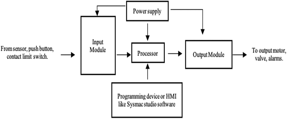
Figure 1: PLC block diagram
SCADA monitors and control the system via a centralized OCC (Operation Control Centre) and HMI (Human-Machine interface) that controls the traction system equipment and entire power supply through SCADA. The functional diagram in Fig. 2 shows the working of Metro railways system using PLC and SCADA. To execute its tasks, the PLC requires a regulated power source of 24V DC. IR sensors, stations, and emergencies feed into the PLC, which generates six output signals such as signal/alarm, train running or halting, and door open or close. The PLC’s output module will send commands from SCADA to the train. An essential feature is that in the case of an emergency, the alarm will send a status point with the value NORMAL or ALARM.
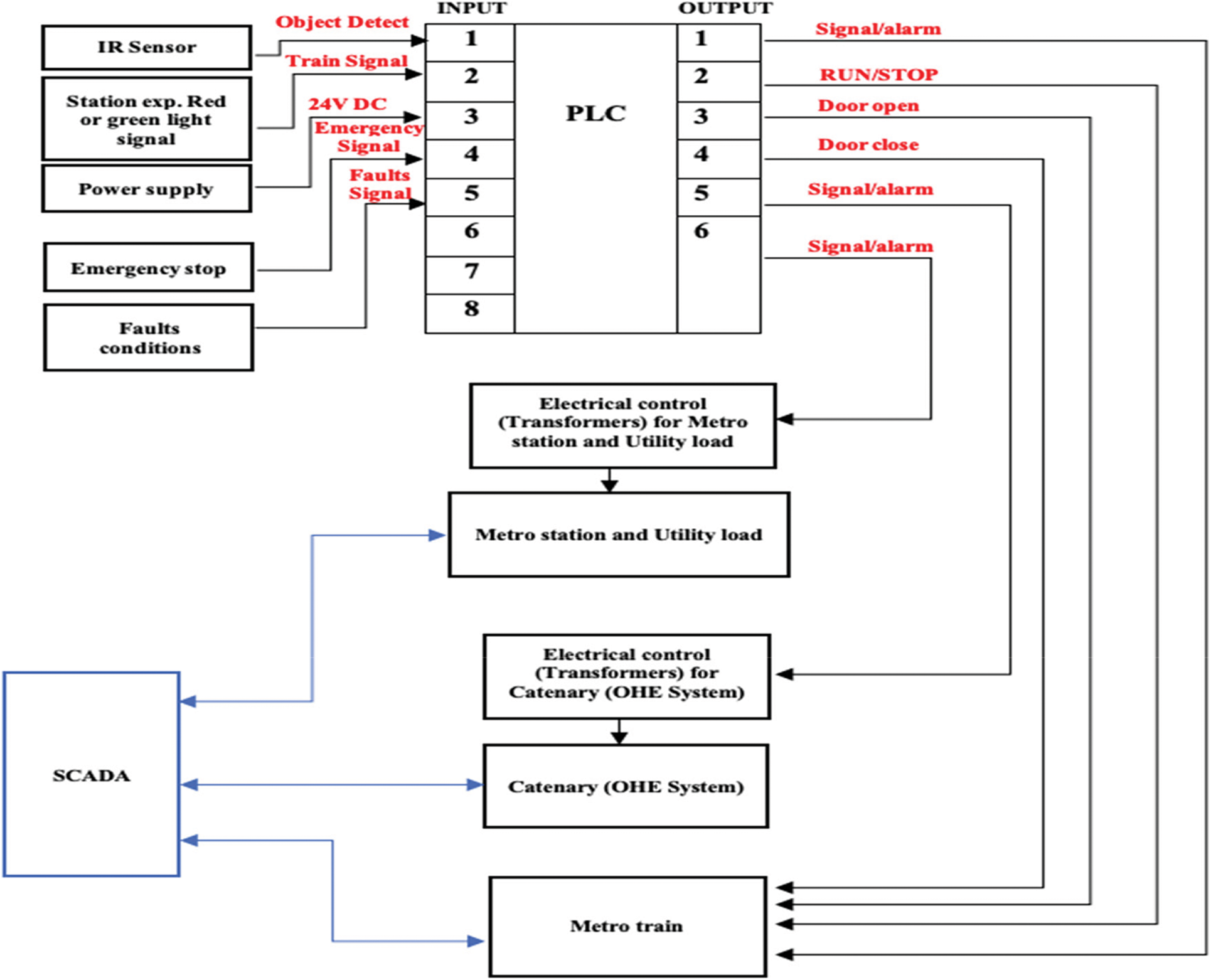
Figure 2: Functional block diagram of metro railways using PLC and SCADA
The prototype of the automated metro railways system operator has four main applications. OCC is the main application of this automated metro train system operator prototype. An operator sits in front of the HMI and controls the metro train system. Each station is linked to the OCC through a remote connection. It has command of all stations and handles all commands such as emergency and congestion with highest priority. CCTV function, Metro stations and metro platform view, and Electrical control are other sub-applications of the system (traction power control and power supply system). Sub application are CCTV function, Metro stations view (Metro train system), Metro platform view, and Electrical control (traction power control and power supply system).
Fig. 3 shows the functioning of the Main application and sub-application and Fig. 4 shows the block diagram and OCC runtime window in SCADA Wonderware Intouch software from where the operator may command and monitor. The IR and reflecting sensors on the RTU are used to scan the programs. If there is a problem with the process, the RTU sends a message to the Master Terminal Unit (MTU), which then sends signals or alerts to the operator on the screen.
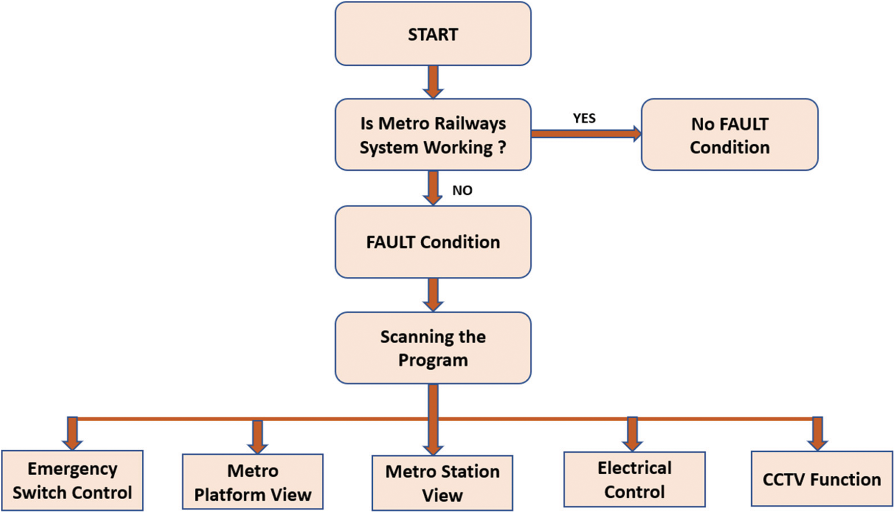
Figure 3: Functioning of main application
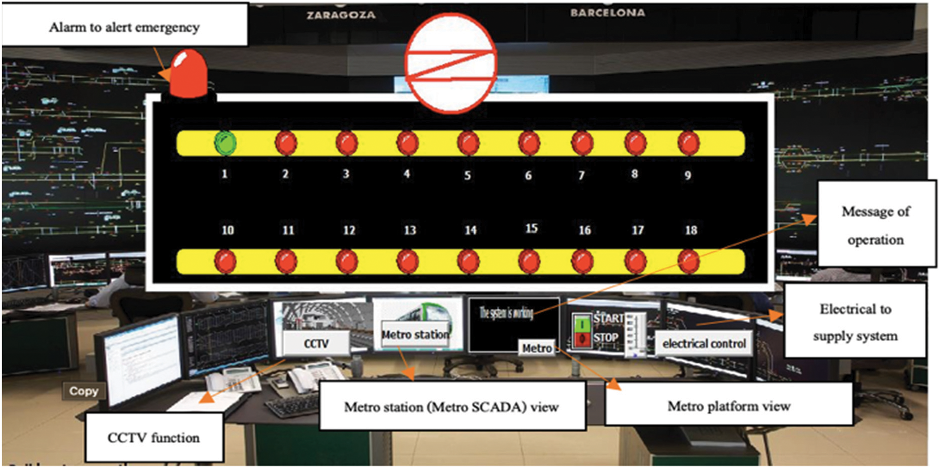
Figure 4: Operational control center runtime window in SCADA Wonderware Intouch software
The operation of the entire system is shown using the flow charts listed below:
3.1 Metro Platforms View Sub-Application
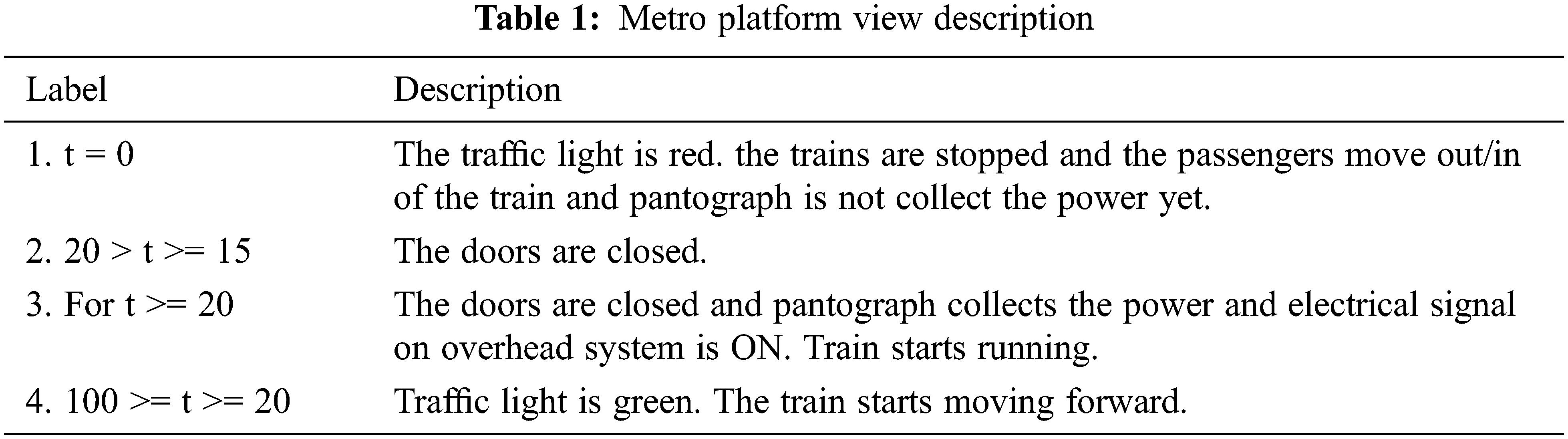
The driver of the trains controls the metro platforms, and the operator of any platform can manage the traffic of the metro station. This flowchart in Fig. 5 and Tab. 1 shows the working of Metro platforms view sub-application. Here, t is timing tag of process/tag of slider.
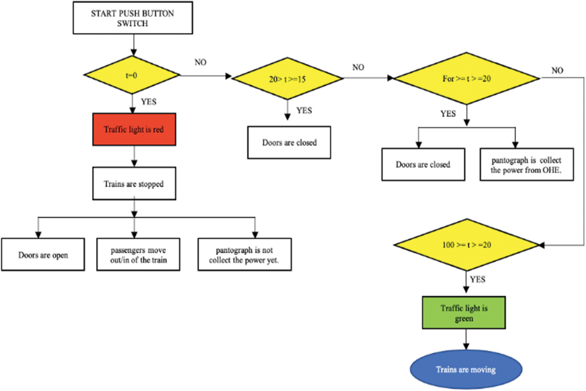
Figure 5: Working of metro platforms view sub-application
3.2 Metro Stations (Traction SCADA System) View Sub-Application
In this flowchart in Fig. 6, functioning of Metro stations (traction SCADA) view sub-application is shown. Metro train starts moving when the switch is turned ON. The LED in the control panel view indicates the proper location of the metro train. This system can track, control and recognize the location of the train even after a power outage or other breakdown. The emergency light will turn ON in case of any fault station and an alert message is displayed by the OCC in the relevant metro station on the HMI or operation display.
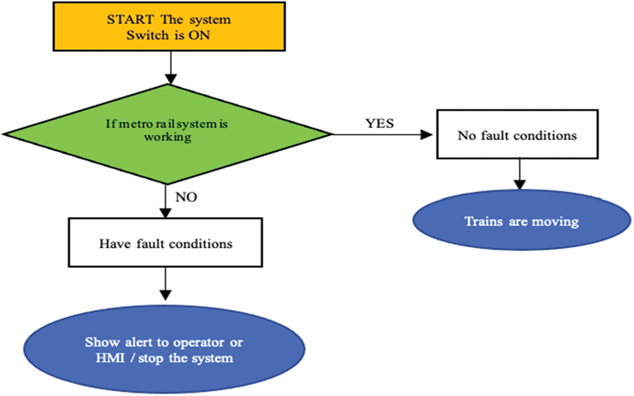
Figure 6: Working of metro stations (traction SCADA system) view sub-application
3.3 Traction Power Control and Power Supply System (Electrical Control)
This flowchart in Fig. 7 shows the functioning of Electrical control view sub-application. Metro rail lines must be electrified with 25 kV, single phase, 50 Hz for overhead equipment to deliver electrical energy to locomotives or trains for operating the motor. The substation, feeding post, and other equipment at the control post and switching station make up the power supply system. A catenary i.e., the overhead equipment (OHE) is used to deliver power to a metro train equipped with a pantograph in metro rail traction systems. Transformer1(T1) is a stepdown transformer for metro stations and Utility load, transformer2(T2) is a stepdown transformer for the catenary, and transformer3(T3) is a step-up transformer for 132 kV incoming line from generating station.
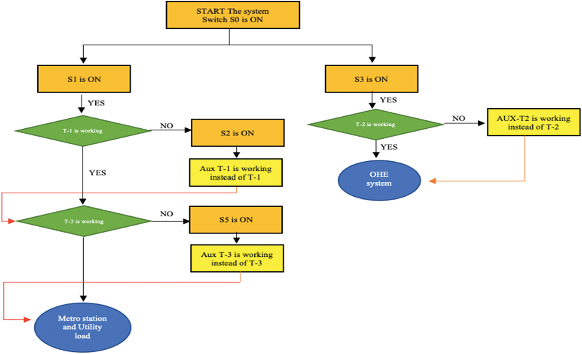
Figure 7: Working of traction power control and power supply system
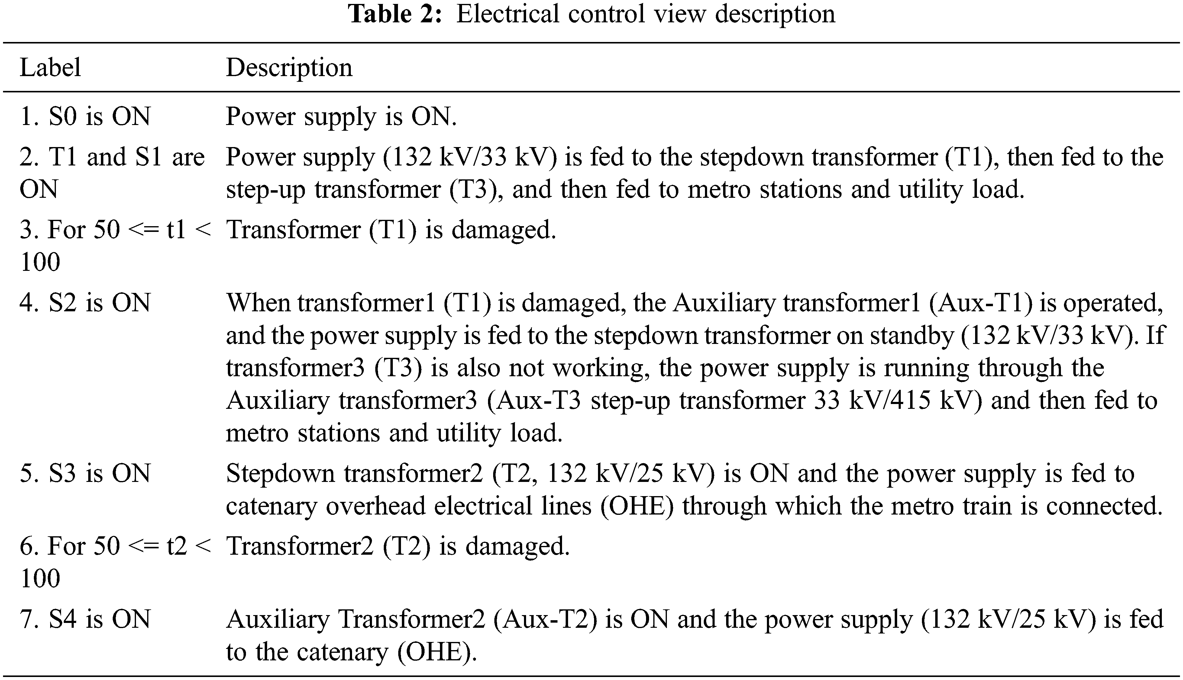
The system is turned on by pressing the button ON S0. The power control and power supply system where t is timing tag of process or the tag of slider is shown here (see Tab. 2).
A sophisticated intrusion detection system (IDS) will be placed at the platform, with comprehensive CCTV or video surveillance coverage of stations, parking, and public spaces. Internal security monitoring systems such as the Automatic Train Supervision (ATS) system, SCADA, Passenger Information System (PIS), and Public Address System (PA) can be implemented to minimize reaction time from personnel. A smart interface is provided to the control room operator using this CCTV approach. They can make quick and effective judgements for running the metro system and delivering the required services. This flowchart shows the functioning of CCTV view sub-application in Fig. 8.
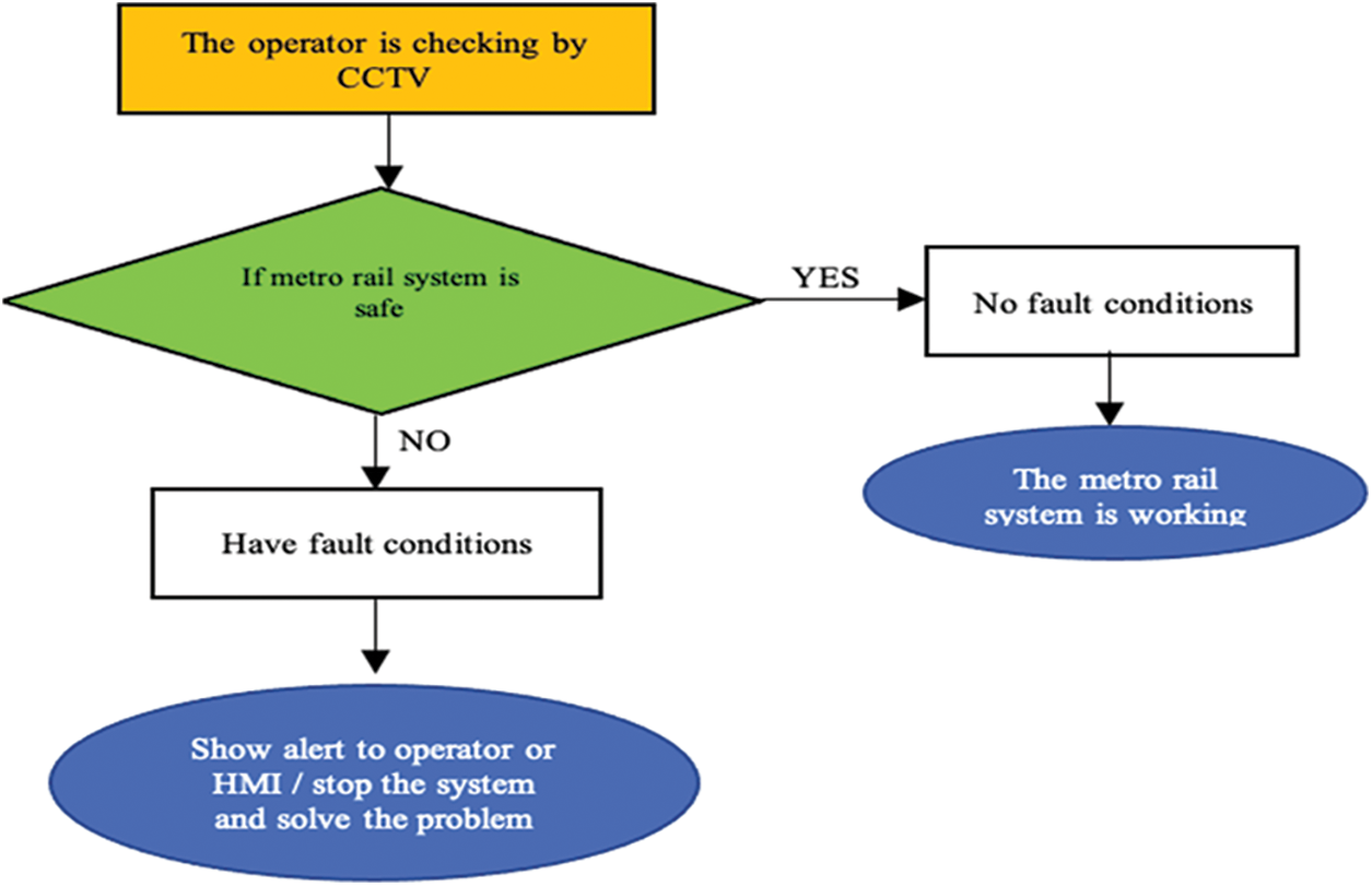
Figure 8: Flowchart for the working of CCTV
A SCADA Wonderware Intouch software window of every operation is shown with the ladder logic program of PLC in this section.
4.1 Operational Control Center (OCC)
Fig. 9 shows the OCC runtime window in SCADA Wonderware Intouch software from where the operator may command and monitor. The IR and reflecting sensors on the RTU are used to scan the programs. If there is a problem with the process, the RTU sends a message to the Master Terminal Unit (MTU), which then sends signals or alerts to the operator on the screen.
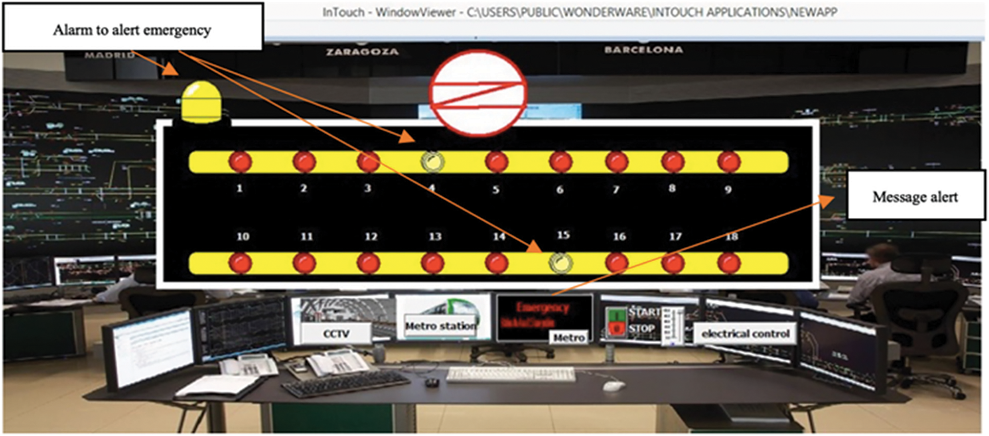
Figure 9: OCC of main application with failure in the system
4.2 Metro Platforms of Sub-Application
All the cases of metro platforms view sub-application are shown here with the help of SCADA system and PLC ladder logic (see Figs. 10–12).
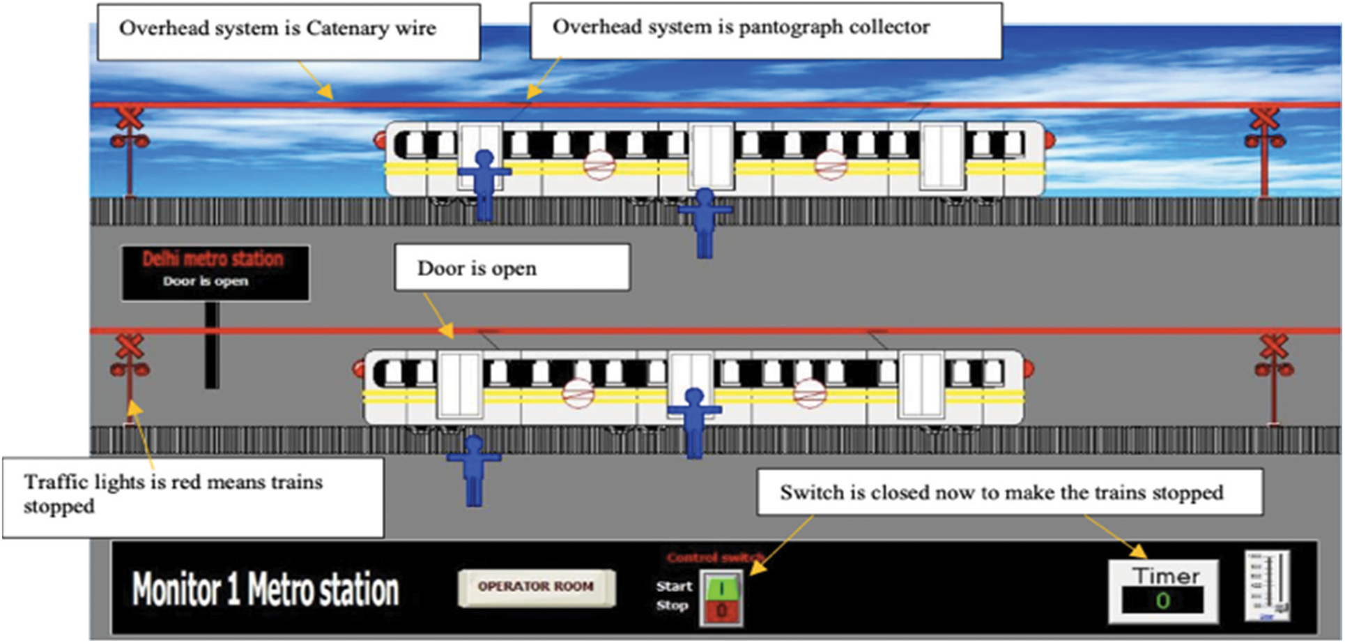
Figure 10: For t = 0, doors are open
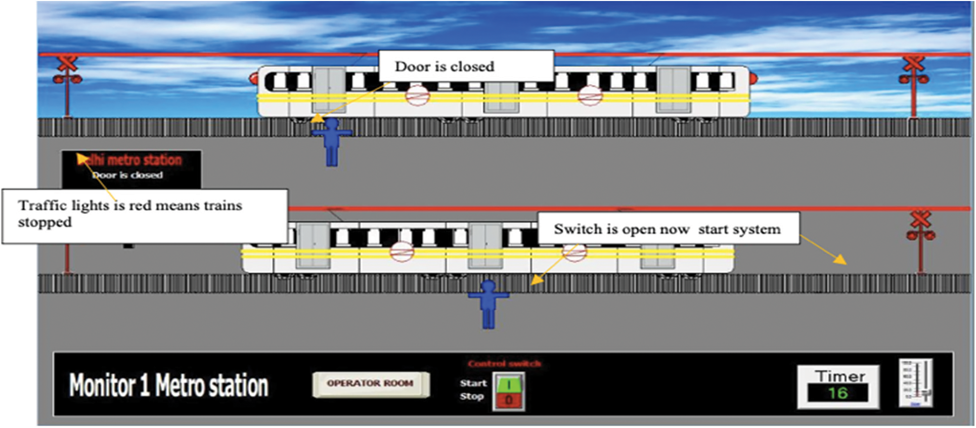
Figure 11: For 20 > t >= 15, doors are closed
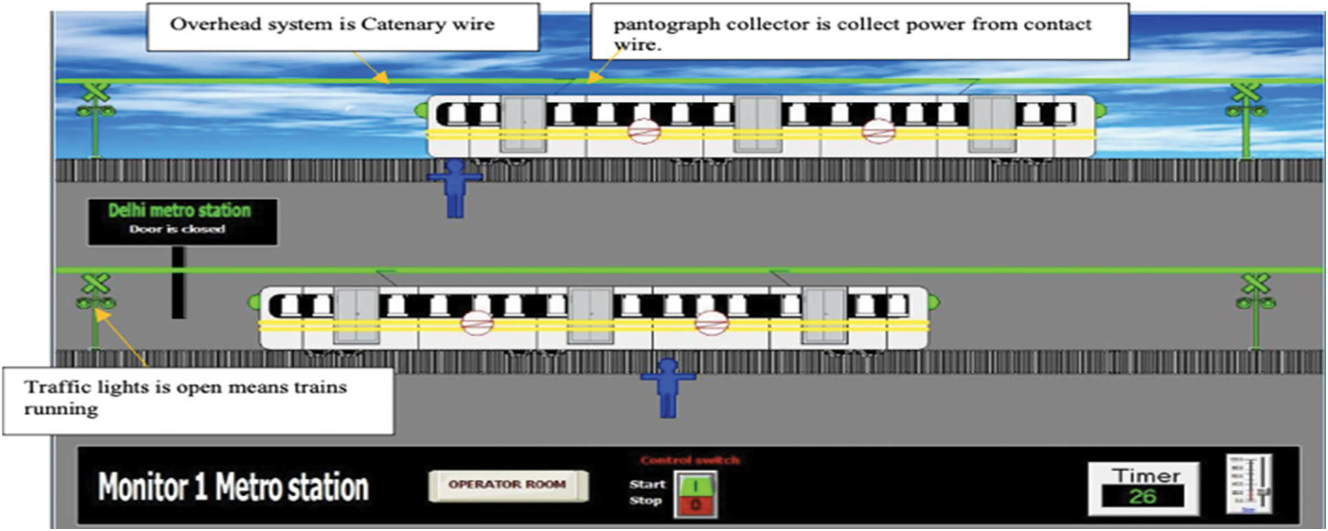
Figure 12: For 100 >= t >= 20, traffic light is green. The train starts moving forward
Fig. 13 shows the Metro stations (traction SCADA) of sub-application. Metro train starts moving when the switch is turned ON. The LED in the control panel view indicates the proper location of metro train. This system can track, control and recognize the location of the train even after a power outage or other breakdown. The emergency light will turn ON in case of any fault station and an alert message is displayed by the OCC in the relevant metro station on the HMI or operation display (see Fig. 14).
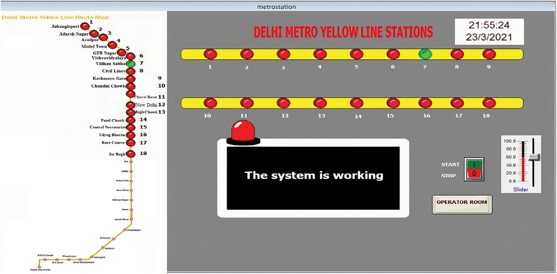
Figure 13: Metro stations (traction SCADA) of sub-application
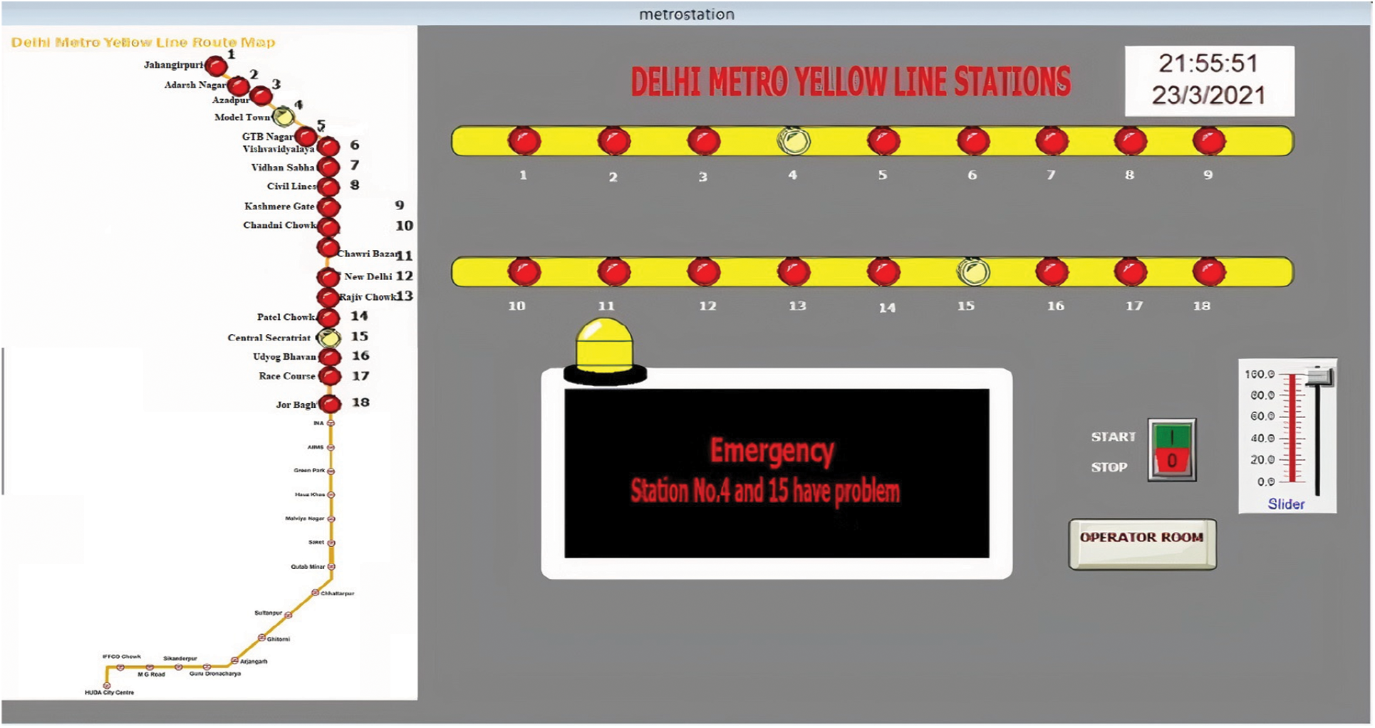
Figure 14: Metro stations (traction SCADA) of Sub-application (failure)
4.3 Electrical Control (Traction Power Control, And Power Supply System) View Sub-Application
Here, the functioning of Electrical control view sub-application is shown. Metro rail lines must be electrified with 25 kV, single phase, 50 Hz for overhead equipment to deliver electrical energy to locomotives or trains for operating the motor. The substation, feeding post, and other equipment at the control post and switching station make up the power supply system. A catenary i.e., the overhead equipment (OHE) is used to deliver power to a metro train equipped with a pantograph in metro rail traction systems. Transformer1(T1) is a stepdown transformer for metro stations and Utility load, transformer2(T2) is a stepdown transformer for the catenary, and transformer3(T3) is a step-up transformer for 132 kV incoming line from generating station.
(1) No Fault Condition: For running the system, a power supply of (132 kV/33 kV) is fed to the stepdown transformer (T1), then fed to the step-up transformer (T3), and then fed to metro stations and utility load. (see Fig. 15).
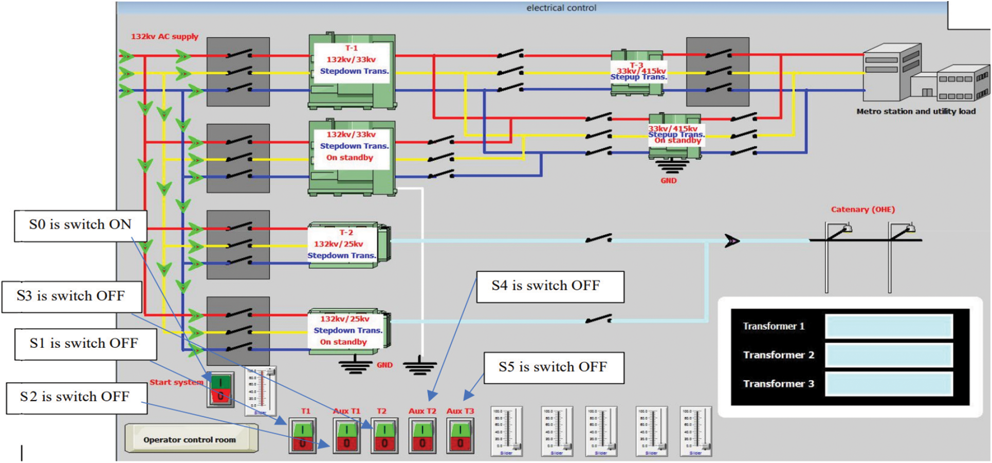
Figure 15: S0 is ON, Power Supply is ON (No fault Condition)
(2) For 50 <= t1 < 100: When transformer1 (T1) is damaged, the Auxiliary transformer1 (Aux-T1) is operated, and the power supply is fed to the stepdown transformer on standby (132 kV/33 kV) (see Fig. 16).
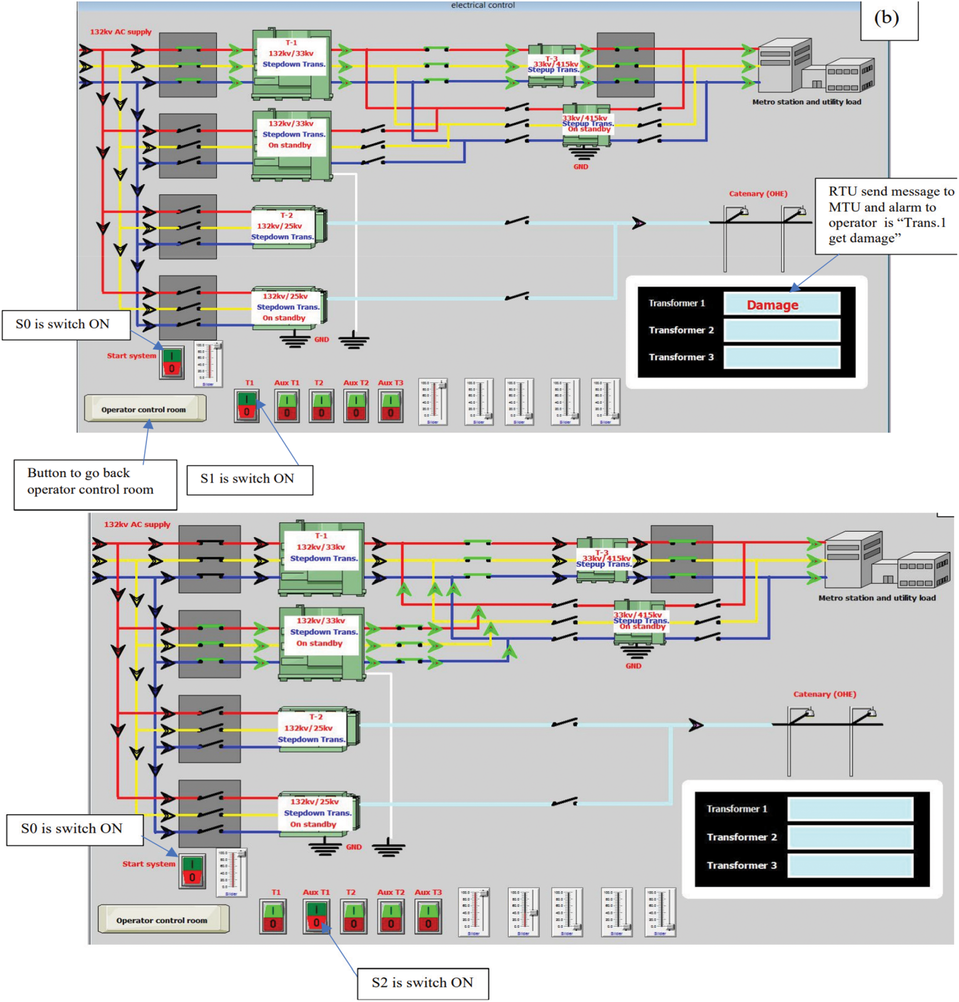
Figure 16: For 50 <= t1 < 100, When Transformer (T1) is damaged, then Aux-T1 is operated
(3) For 50 <= t2 < 100: Stepdown transformer2 (T2, 132 kV/25 kV) is ON and the power supply is fed to catenary overhead electrical lines (OHE) through which the metro train is connected. If transformer2(T2) gets damaged, then Auxiliary transformer2 (Aux-T2) provides the power in case of transformer2(T2). Switch ON S0, S2, and S4 means the system is working.
(4) When Stepdown transformer3(T3) gets damaged, then Auxiliary transformer3 (Aux-T3) provide the power in case of transformer3(T3). Switch ON S0, S4, and S5 means the system is working (see Fig. 17).
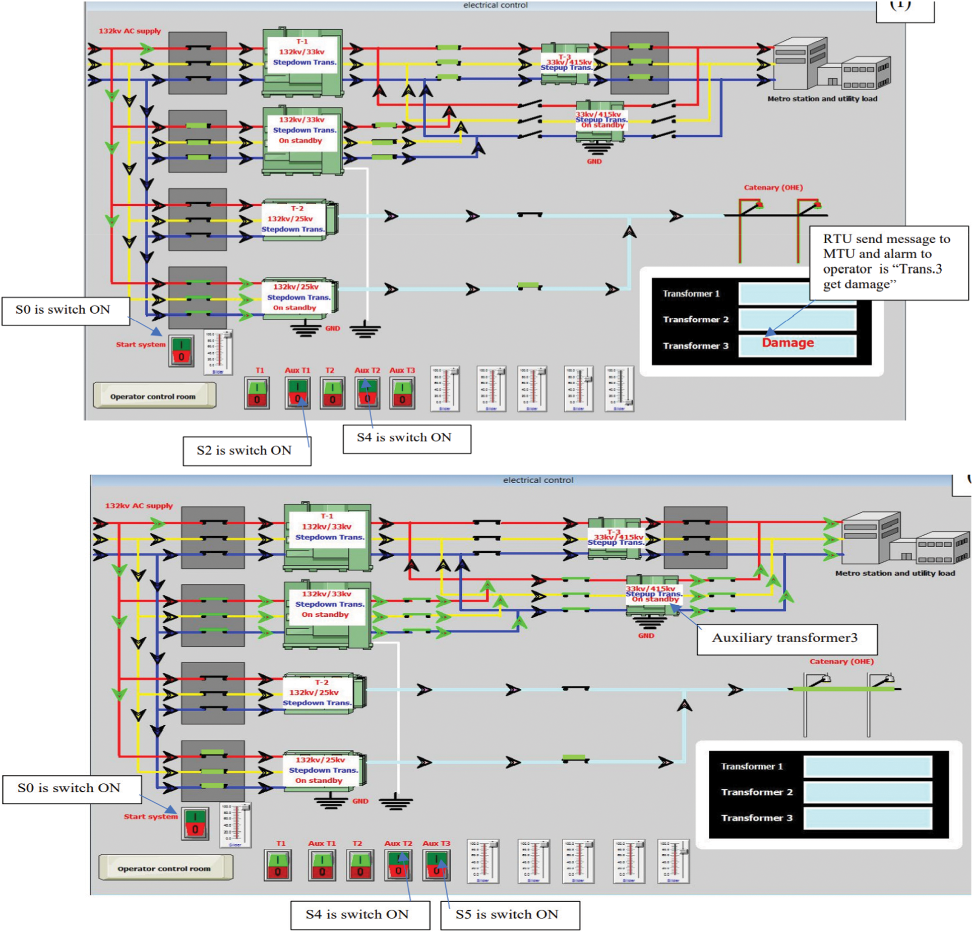
Figure 17: When T3 gets damaged, then Aux-T3 provides the power in case of T3
The SCADA Wonderware Intouch software window of CCTV operation is shown in Fig. 18.
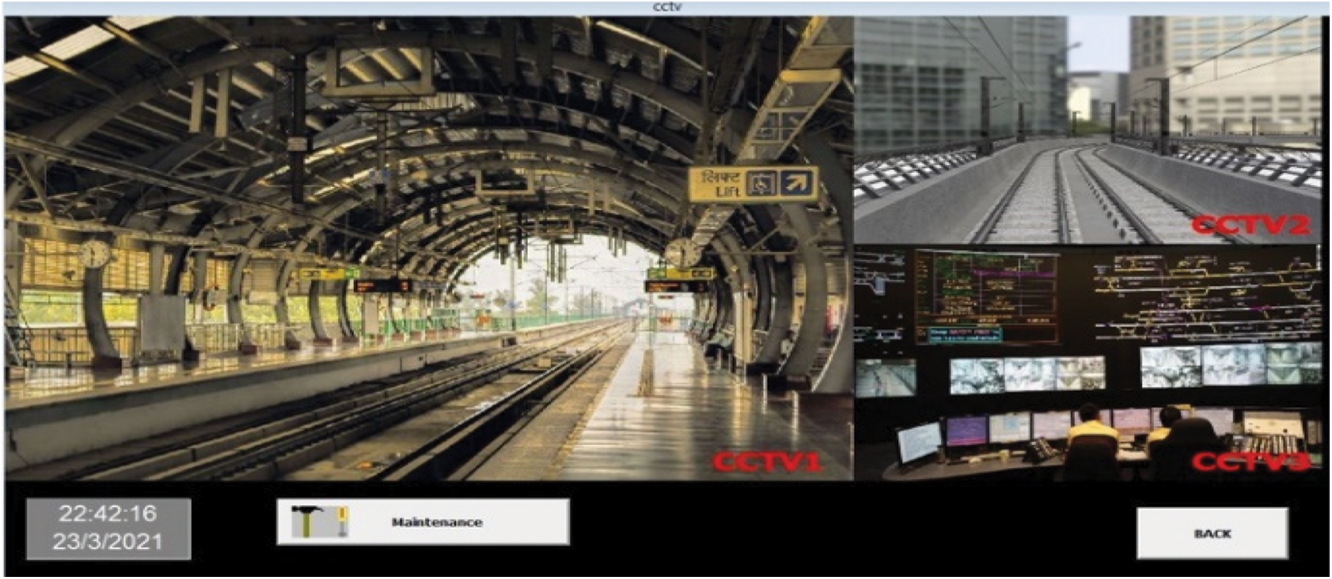
Figure 18: CCTV of sub-application
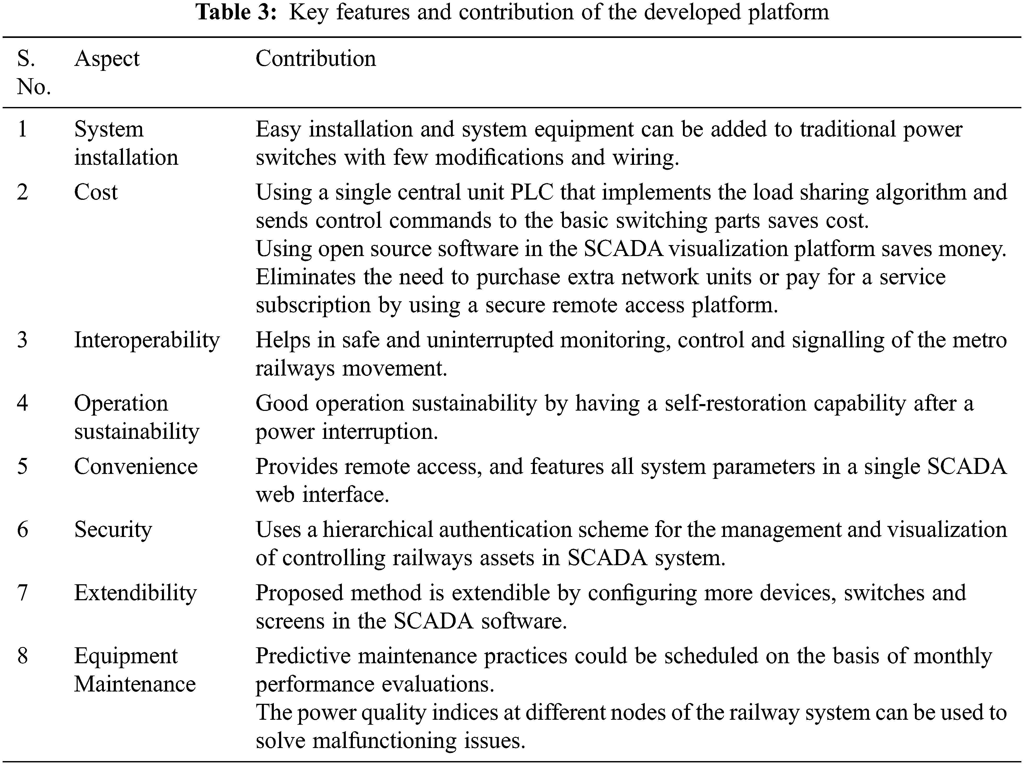
Industrial Control Systems (ICS) and SCADA systems play a critical role in the management and regulation of Critical Infrastructure. SCADA systems are bringing us closer to the real-time application world. SCADA systems increase the efficiency of a control system operation while also providing improved protection for the equipment it uses. Furthermore, it increases employee productivity. SCADA frameworks use an established monitoring platform, advanced communication system, and sensors to provide required information and timely alerts/warnings to observing stations. The designed SCADA system offers continuous access and visualization of all the data in a more efficient and timely manner. It also provides a centralized and thorough display of parameters. The use of “Wonderware Intouch” software facilitates the gathering and visualization of data. The data collecting procedure in the proposed SCADA system is primarily centered on creating adequate communication links between the SCADA server (master station) and numerous PLCs and sensors that measure and send the readings of a variety of valuable parameters. The proposed system decreases the false error percentage in comparison to the traditional systems (Fig. 19). Tab. 3 shows the key features and contribution of the developed platform.
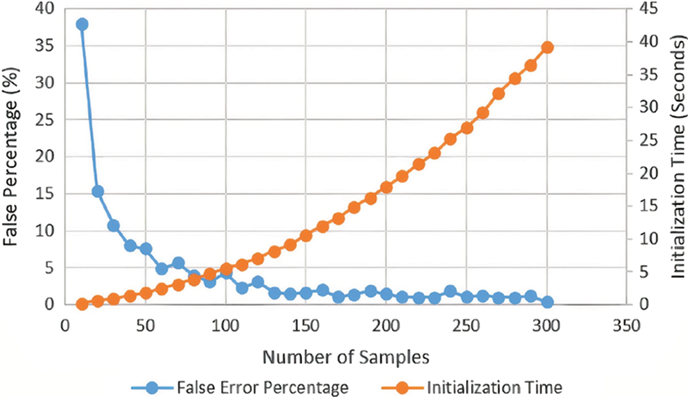
Figure 19: Initialization time and false error percentage of the proposed system
In this paper, a PLC and SCADA based Real time monitoring and train control system for the Metro Railways has been used in to minimize the failure. Here, SCADA is used for the visualization of an automated process operation and then the whole operation is regulated using PLC. The PLC used here is OMRON (NX1P2-9024DT1) and OMRON’s Sysmac studio programming software is used for developing the ladder logic of PLC. Wonderware Intouch SCADA software is used for the visualization of the operation. This system helps in detecting exact location, avoiding train collisions and opening emergency exit even after the interruption of power system with the use of Programmable Logic Controller. This system overcomes the drawbacks of the current CATC system comprising of automatic train protection, signaling and operation systems.
Acknowledgement: This work has been carried out under the supervision of Prof. S. Indu and Prof. Neeta Pandey, Department of ECE, Delhi Technological University, and I (Ishu Tomar) pay immense gratitude towards my guides for enlightening me through the process.
Funding Statement: The authors received no specific funding for this study.
Conflicts of Interest: The authors declare that they have no conflicts of interest to report regarding the present study.
1. N. Valadão, G. Künzel, I. Müller and C. E. Pereira, “Industrial wireless automation: Overview and evolution of WIA-PA,” IFAC-PapersOnLine, vol. 51, no. 10, pp. 175–180, 2018. [Google Scholar]
2. B. Tomar and N. Kumar, “PLC and SCADA based industrial automated system,” in Proc. 2020 IEEE Int. Conf. for Innovation in Technology (INOCON), Bangluru, India, pp. 1–5, 2020. [Google Scholar]
3. N. Nadgauda and S. A. Muthukumaraswamy, “Design and development of industrial automated system using PLC-SCADA,” in Proc. 2019 IEEE 10th GCC Conf. & Exhibition (GCC), Kuwait, pp. 1–6, 2019. [Google Scholar]
4. M. Longo and M. Bramani, “The automation control systems for the efficiency of metro transit lines,” in Proc. 2015 AEIT Int. Annual Conf. (AEIT), Naples, Italy, pp. 1–6, 2015. [Google Scholar]
5. S. Sripriya, V. Divya and T. Babu, “Building management system in metro rail,” in Proc. 2017 Third Int. Conf. on Sensing, Signal Processing and Security (ICSSS), Chennai, India, pp. 409–413, 2017. [Google Scholar]
6. F. Shang, J. Zhan and Y. Chen, “Distributed model predictive control for train regulation in urban metro transportation,” in Proc. 2018 21st Int. Conf. on Intelligent Transportation Systems (ITSC), Maui, HI, USA, pp. 1592–1597, 2018. [Google Scholar]
7. Y. Cao, L. Ma and Y. Zhang, “Application of fuzzy predictive control technology in automatic train operation,” Cluster Computing, vol. 22, no. 1, pp. 123–132, 2018. [Google Scholar]
8. S. Krishna, “Standardization of signalling and train control systems for metro railways,” Report of the sub-committee Ministry of Urban Development, Government of India, New Delhi, India, 2013. [Google Scholar]
9. H. Wang, N. Zhao, B. Ning, T. Tang and M. Chai, “Safety monitor for train-centric CBTC system,” IET Intelligent Transport Systems, vol. 12, no. 8, pp. 931–938, 2018. [Google Scholar]
10. Y. Wang, L. Chen, J. Wei, D. Kirkwood, Q. Xu et al., “On-line conformance testing of the communication-based train control (CBTC) system,” in Proc. IEEE Int. Conf. on Intelligent Rail Transportation (ICIRT), Birmingham, England, pp. 328–333, 2016. [Google Scholar]
11. Q. Wei, R. Niu and T. Tang, “Assessment of metro signaling system resilience,” in Proc. 2018 Int. Conf. on Intelligent Rail Transportation (ICIRT), Singapore, pp. 1–5, 2018. [Google Scholar]
12. E. Dimitrova, “Analysis of automatic control systems for metro trains,” in Proc. 2019 11th Electrical Engineering Faculty Conf. (BulEF), Varna, Bulgaria, pp. 1–4, 2019. [Google Scholar]
13. X. R. Zhang, W. F. Zhang, W. Sun, X. M. Sun and S. K. Jha, “A robust 3-D medical watermarking based on wavelet transform for data protection,” Computer Systems Science & Engineering, vol. 41, no. 3, pp. 1043–1056, 2022. [Google Scholar]
14. X. R. Zhang, X. Sun, X. M. Sun, W. Sun and S. K. Jha, “Robust reversible audio watermarking scheme for telemedicine and privacy protection,” Computers Materials & Continua, vol. 71, no. 2, pp. 3035–3050, 2022. [Google Scholar]
15. E. R. Alphonsus and M. O. Abdullah, “A review on the applications of programmable logic controllers (PLCs),” Renewable and Sustainable Energy Reviews, vol. 60, no. 8, pp. 1185–1205, 2016. [Google Scholar]
16. F. Yan, C. Gao and T. Tang, “A safety management and signaling system integration method for communication-based train control system,” Urban Rail Transit, vol. 3, no. 2, pp. 90–99, 2017. [Google Scholar]
17. A. Üstündağ and Ç. Gençer, “Designing the clamp system with the emergency braking system in the trains by using PLC and SCADA,” in 2021 IEEE 11th Annual Computing and Communication Workshop and Conference (CCWC), NV, USA, pp. 1436–1441, 2021. [Google Scholar]
18. X. Wang, S. Li, T. Tang and L. Yang, “Event-triggered predictive control for automatic train regulation and passenger flow in metro rail systems,” IEEE Transactions on Intelligent Transportation Systems, vol. 23, no. 3, pp. 1–14, 2020. [Google Scholar]
19. K. Tabassum, “An intelligent metro tracking system for Riyadh smart city,” International Journal of Information Technology, vol. 12, no. 4, pp. 1103–1109, 2020. [Google Scholar]
PLC Ladder Logic for the proposed system


 | This work is licensed under a Creative Commons Attribution 4.0 International License, which permits unrestricted use, distribution, and reproduction in any medium, provided the original work is properly cited. |