DOI:10.32604/iasc.2023.028930
| Intelligent Automation & Soft Computing DOI:10.32604/iasc.2023.028930 | |
| Article |
THD Reduction for Permanent Magnet Synchronous Motor Using Simulated Annealing
1Department of Electrical & Electronics Engineering, Kalaivanar N S K College of Engineering, Nagercoil, 629001, India
2Department of Electrical & Electronics Engineering, Vignana Bharathi Institute of Technology, Hyderabad, 501301, India
3Department of Electronics and Communication Engineering, Vel Tech Rangarajan Dr.Sagunthala R & D Institute of Science and Technology, Chennai, 600062, India
4Department of Information Technology, St. Xavier’s Catholic College of Engineering, Nagercoil, 629003, India
*Corresponding Author: N. Herald Anantha Rufus. Email: drrufus@veltech.edu.in
Received: 22 February 2022; Accepted: 19 April 2022
Abstract: Any nonlinear behavior of the system is analyzed by a useful way of Total Harmonic Distortion (THD) technique. Reduced THD achieves lower peak current, higher efficiency and longer equipment life span. Simulated annealing (SA) is applied due to the effectiveness of locating solutions that are close to ideal and to challenge large-scale combinatorial optimization for Permanent Magnet Synchronous Machine (PMSM). The parameters of direct torque controllers (DTC) for the drive are automatically adjusted by the optimization algorithm. Advantages of the PI-Fuzzy-SA algorithm are retained when used together. It also improves the rate of system convergence. Speed response improvement and harmonic reduction is achieved with SA-based DTC for PMSM. This mechanism is known to be faster than other algorithms. Also, it is observed that as compared to other algorithms, the projected algorithm yields a reduced total harmonic distortion. As a result of the employment of Space Vector Modulation (SVM) technique, the system is resistant to changes in motor specifications and load torque. Through MATLAB & Simulink simulation, the experiment is done and the performance is calculated for the controller.
Keywords: PMSM; simulated annealing; space vector modulation; direct torque control; THD
The use of electrical energy has recently become inevitable in the current days. Approximately two-thirds of electricity is utilized by motors in power industries worldwide. Electric motors, power electronics drive circuits, sensors, and controllers are the major components of typical drive systems. As per the recent advances in control theories, semiconductor power devices and magnetic materials, permanent magnet synchronous motor drives have become inevitable in motion-control applications. Normally, PMSM is a high-performing and high-efficiency motor drive. The characteristics like full torque control at zero speed, quick acceleration and deceleration, and its smooth spinning over the entire speed range make PMSM to perform high. As compared to conventional motors, PMSM consumes 30% less energy. Removal of secondary conductive losses in the rotor leads to this energy saving, noise reduction, low rotor inertia, motor size reduction and efficient heat dissipation are all due to the PMSM with exterior windings and inner permanent magnet rotor. Also, recent developments in PMSM drives make them more suitable for industrial applications which require high torque at low speeds. Applications of PMSM drives can be found in the paper and textile industry and in special applications for marine. Also, it can be applied in traction, robotics and aerospace due to its compactness, increased power, increased intelligence and high torque density. In recent years, many studies have been undertaken for applying various methods to reduce the impact of uncertainties. On a fundamental level, traditional PID controllers are usually employed in industries because of their simplicity, candid control structure and economical nature. On varying the rotating magnetic field frequency, the motors synchronous speed can be controlled. As production and maintenance costs are higher for synchronous motors, industries have the challenge to improve the performance of motors with accurate speed tracking, smooth torque output and minimum ripple during transients. The PMSM satisfies the criteria required by the industry.
DTC is one of the best methods to control torque of AC machines. The higher torque control rate and speed sensitivity make DTC as superior over other methods. Rotor status information is needed to implement the field orientation process in a flux vector drive under magnetic operating conditions. The pulse encoders give the details about angular position and rotor speed to acquire rotor status. The high cost of pulse encoders needs a suitable alternative. The necessary control variables for DC drives are motor flux and torque, which in turn are controlled by the stator current. DTC deeds motor flux and torque as they are control variables to control the speed of AC drives. For designing and developing three-phase sine wave voltage source inverters, SVM is the proven best method.
SVM becomes the best suited technique to provide pulse-width modulation for voltage-fed converter drives due to its higher harmonic quality and wider range of operation. A speed PI controller generates the reference torque, and the control approach is Dead Beat DTC. Under external disturbances, the PI controller has a low dynamic and poor precision. The rate of convergence is very low in this method [1]. Adaptive internal type 2 Fuzzy controller is used for modeling the unknown functions. In this control method, all well-designed signals are bounded [2]. In conventional methods of DTC, very large ripples in torque responses are obtained, especially in electric vehicle applications, as a result of reverse voltage selection [3]. The block diagram of Simulated Annealing (SA) based PMSM control is shown in Fig. 1.
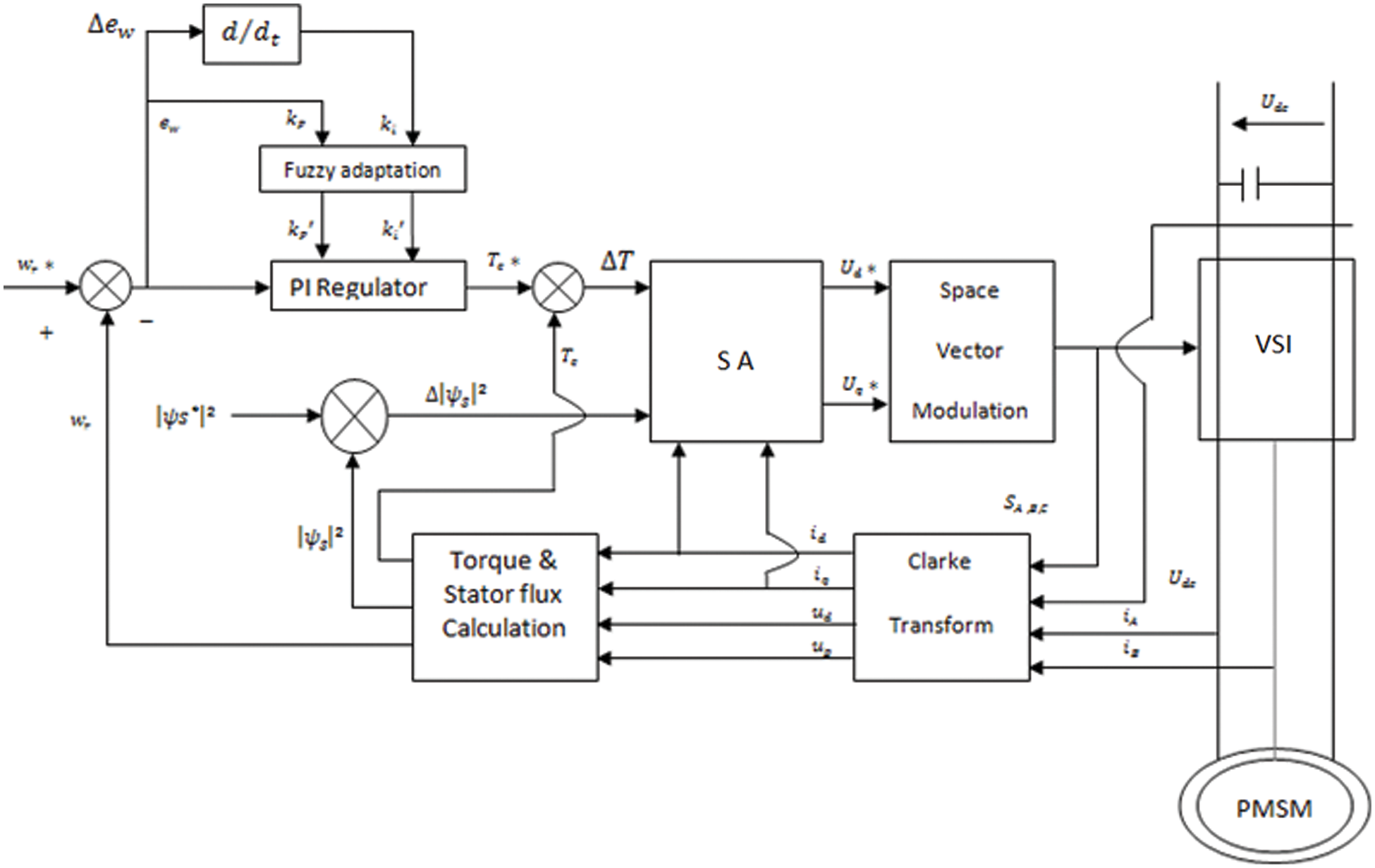
Figure 1: Block diagram of Simulated Annealing based PMSM
This study proposes a simulated annealing based control system for rotor position control in PMSM drives. This study is more appropriate for close to ideal solutions in large scale combinatorial optimization problems, such as Random Search. This optimization problem investigates an objective function’s parameter space, making it simple to minimize the objective functions. Likewise, here the iteration is based on the minimum of ripple in torque and flux by finding the correct parameters to control the PMSM drive. DTC-SVM played a major role in this work.
Performance of suggested method has been successfully proven by simulated and experimental findings. The following is description of the structure of the paper. The problem formulation and the dynamic analysis of the PMSM servo drive are stated in Section 2. Unit 3 comprises the Simulated Annealing framework, DTC model, and SVM. Simulation and experimental analysis were used to confirm the correctness of the design approach and the resilience of the suggested controller. Under load fluctuations and parameter uncertainties, the dynamic performance of the drive system is investigated. Section 4 contains validation with experimental simulations and results. Inference and future scope are given in Section 5.
A DTC-PMSM with fuzzy comparator for PMSM in low speed applications is stated in [1–5] to minimize the variation in flux and torque. Speed, flux and torque variables in the stationary reference frame are controlled by the optimum control theory. Thus the structure becomes simple and a low speed operation is achieved [6,7], but the level of THD is high in the range of 11% and it leads to high peak current at low speed. The substantial current harmonics are generated in the DTC-PMSM system due to back electro-motive force distortion. The problems connected with direct torque control of PMSM engines are recognized as high settling and rise time, overshoot and undershoot issues, low transient response and high computational complexity based on literature surveys [8–10]. Here the motor requires suitable controllers for attaining targeted performance. Due to the simple control structure and less complexity [11], traditional PI controllers are commonly used in industries. But it introduces problems likes load disturbances, parametric variations and nonlinearity that are induced by these controllers. Also, an accurate linear mathematical model is required for PI controllers [12]. The linear PI can no longer be sufficient, as the PMSM machine has a nonlinear model [13,14]. In this work PI controller is combined with Fuzzy adaptation for its performance improvement, also for better turning of proportional and integral controller constants. The controlled input from the PI controller is applied to the optimization approach for improved gain. The energy upgrade and adjustment of the energy level in the SA algorithm results in optimal input torque selection for PMSM, which improves the switching pattern in the SVM. As a result, the THD has decreased.
The PMSM is provided with a three-phase input. The three-phase model is first converted to an alpha-beta transformation using Clark's transformation. Let
Same way
Here
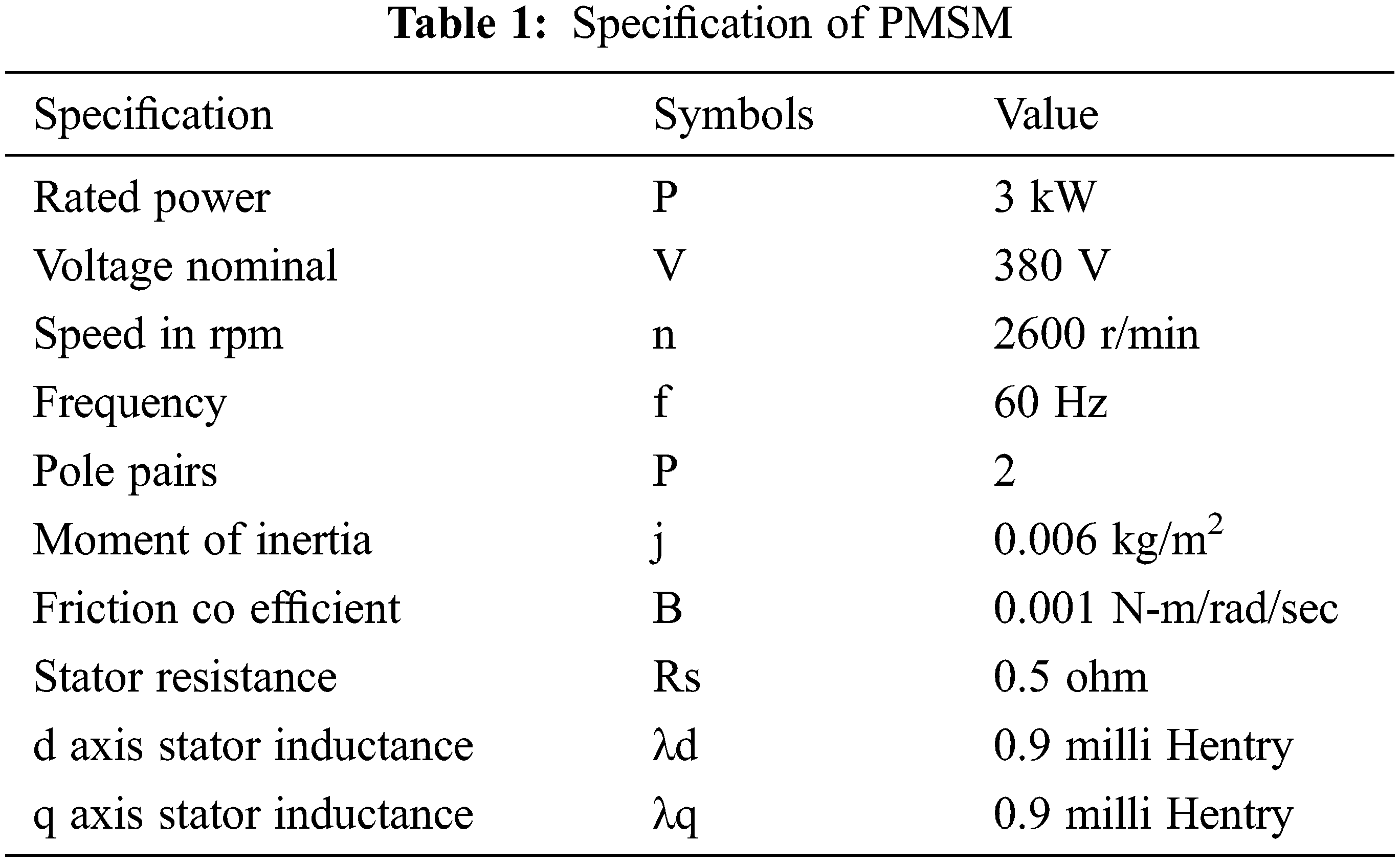
Over each stator winding, voltage E is the sum of the resistive voltage drop and the voltage induced by time-varying flux linkages. In the rotating reference frame, the voltage equations of the stator windings are given as in (1) and (2). The electromagnetic torque is then calculated using FOC with the d-axis current set to zero [2], as shown in (3) and (4). Tab. 1 lists the parameters of a drive system.
where
P is the number of pole
Because the motor's torque and current are proportional, the torque equation can be written as
where
The sum of all opposing torques is calculated using Newton's law, with load torque equaling the motor's torque. As a result, the torque equation is
The back emf is always proportional to the speed of the given motor. And replacing the proportionality constant as KB, the equation becomes
where,
Using the co-energy form, torque is defined as a change in energy per change in angle. The energy equation can be expressed as,
iabcs is the instantaneous stator current in amps
idqr is the rotor reference frame current
I stands for Identity Matrix. and
The electro-mechanical torque is represented as
The torque and rotor speed relations are,
where j stands for inertia in Kg-m2,
At every sampling period, a single stator voltage is chosen and is kept constant for the entire duration. High and small torques are not differentiated by the switching technique. This introduces an extra torque ripple during steady state operation. A reference stator voltage space vector is determined at all sampling periods, in this control scheme. This is done by the proper selection of inverter switch states and by calculating time period for every state [15–17].
Every sampling period, a reference space vector, is calculated in the control scheme. This is accomplished by carefully selecting the inverter's switch states and calculating the time span for each condition [18]. The abc- axis can be transformed to x-y axis is represented as,
which can also be written as
where,
The space vector representation is
where
Using line voltage as a reference, the rms output voltage’s α-β components can be written as a function of
The performance vector U is defined when the output voltages are purely sinusoidal. As
where
3 Simulated Annealing in Random Search Approach
To produce a solution to combinatorial optimization issues, this algorithm can be applied. Solutions to the issues are equal to states in a physical system and the cost of a solution is equivalent to a state's "energy." Flowchart of random search SA is depicted in Fig. 2.
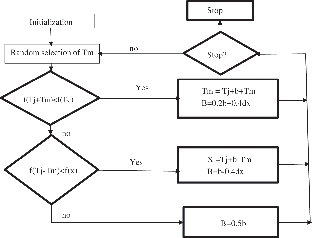
Figure 2: Random search method flow chart
The Simulated annealing based PMSM algorithm is demonstrated below.
• Step 1: Initialization with a Torque N-m random initial value.
• Step 2: With a given move, do the operation.
• Step 3: Measure score: calculate the torque and flux values because of the move made.
• Step 4: Choose- Accept or reject the transfer, depending on the shift in torque and flux values. Based on this information, the switching pattern of space vector modulation Sa, Sb, Sc is based.
• Step 5: Update and repeat- The values are updated. Go back to Step 2 and repeat the process until it reaches the best performance
4 Simulation Results and Discussion
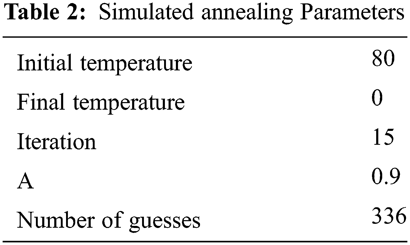
The method of heating up a solid and then cooling it down until it becomes a crystal is called simulated annealing. Simulated annealing consists mainly of a sequence of iterations being repeated. The two energy level sets Ei and Ej are obtained from the respective current solution and test solution. If Ei − Ej < 0, then trail solution is accepted and the current solution is substituted. Else, acceptance or refusal depends on the acceptance of probability by Boltzman. A move of every solution to all neighborhood state space should be within the cooling schedule of initial temperature. The direct torque PI controller parameters are optimized using a simulated method of annealing. The simulated annealing parameters are displayed in Tab. 2.
The simulated results of simulated annealing based direct torque control PMSM are investigated. The speed control of SA-PMSM is in Fig. 3 and the speed tracking with different speeds is plotted in Fig. 4. The reference speed of 6000 rpm and 4000 rpm are compared with the response of PMSM with SA controller.
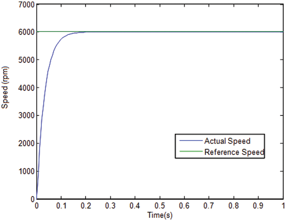
Figure 3: Speed response of SA based PMSM
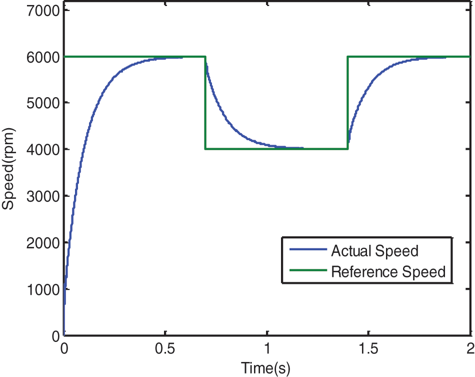
Figure 4: Speed tracking with different speed
The torque response of DTC-SA-PMSM is illustrated in Fig. 5. The variation of torque under various times is analyzed.
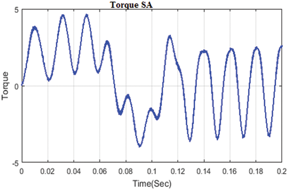
Figure 5: Torque response of SA based PMSM
The three phase voltage utilization and the THD analysis of DTC-SA-PMSM is depicted in Figs. 6 and 7 respectively.
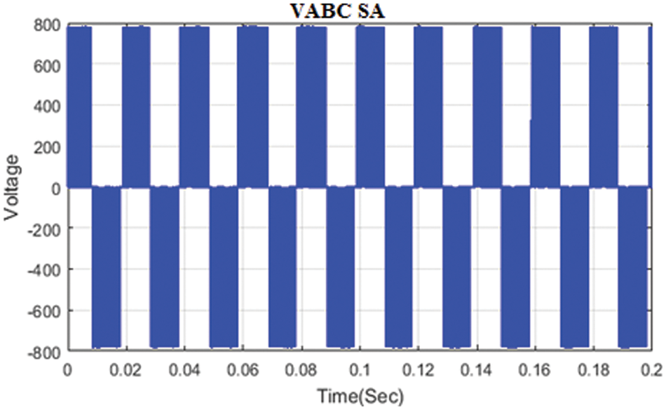
Figure 6: Three phase voltage output of SA based PMSM
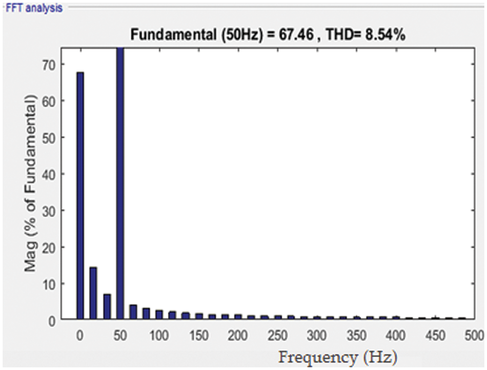
Figure 7: Total Harmonic Distortion chart of PMSM using SA
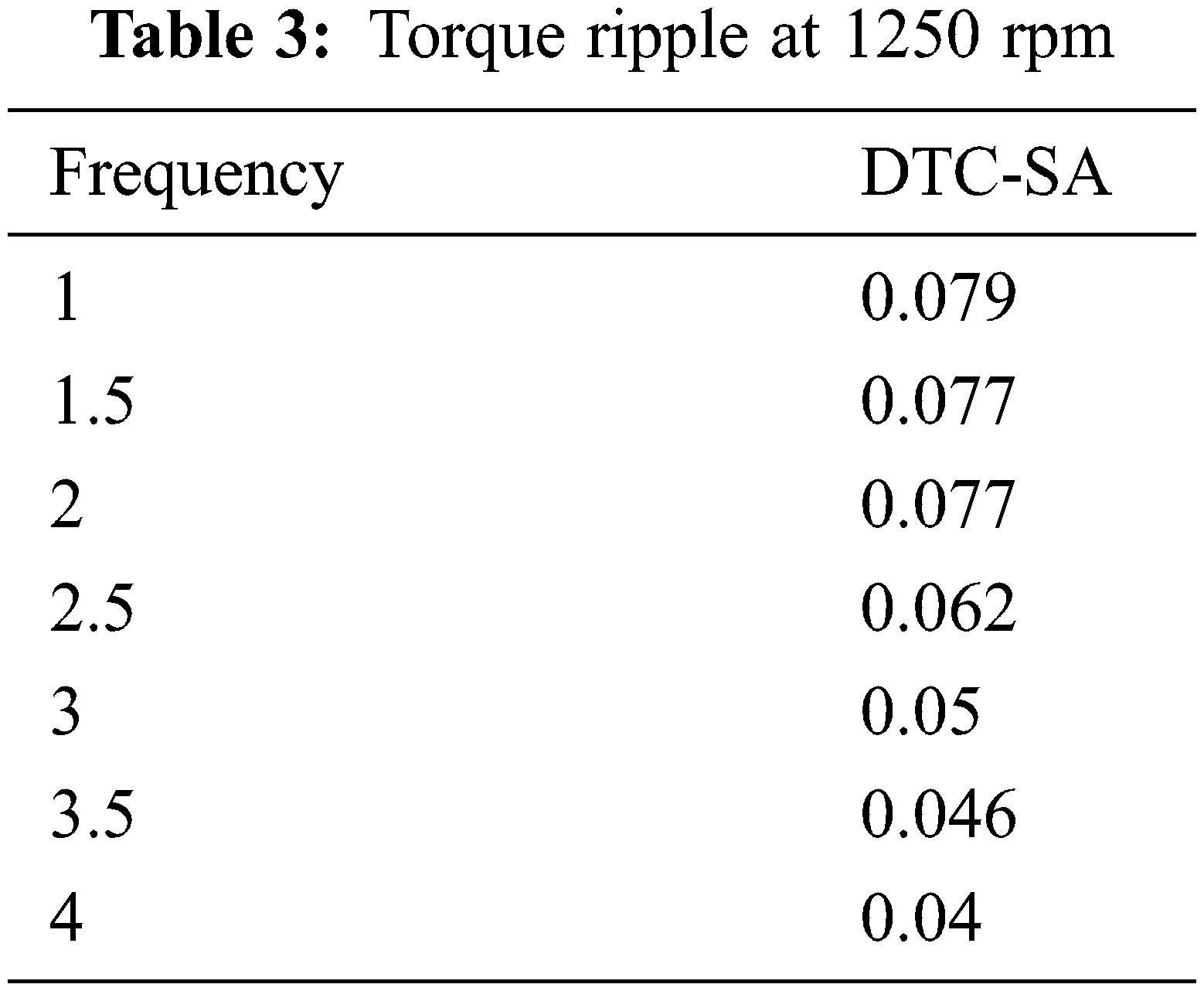
The various ripples are listed in Tab. 3 with respect to various frequency levels.
The speed and load change with different scaling is depicted in Fig. 8 and Fig. 9.
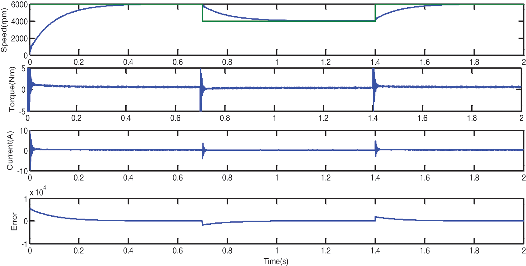
Figure 8: Speed variation of PMSM motor with full load-SA
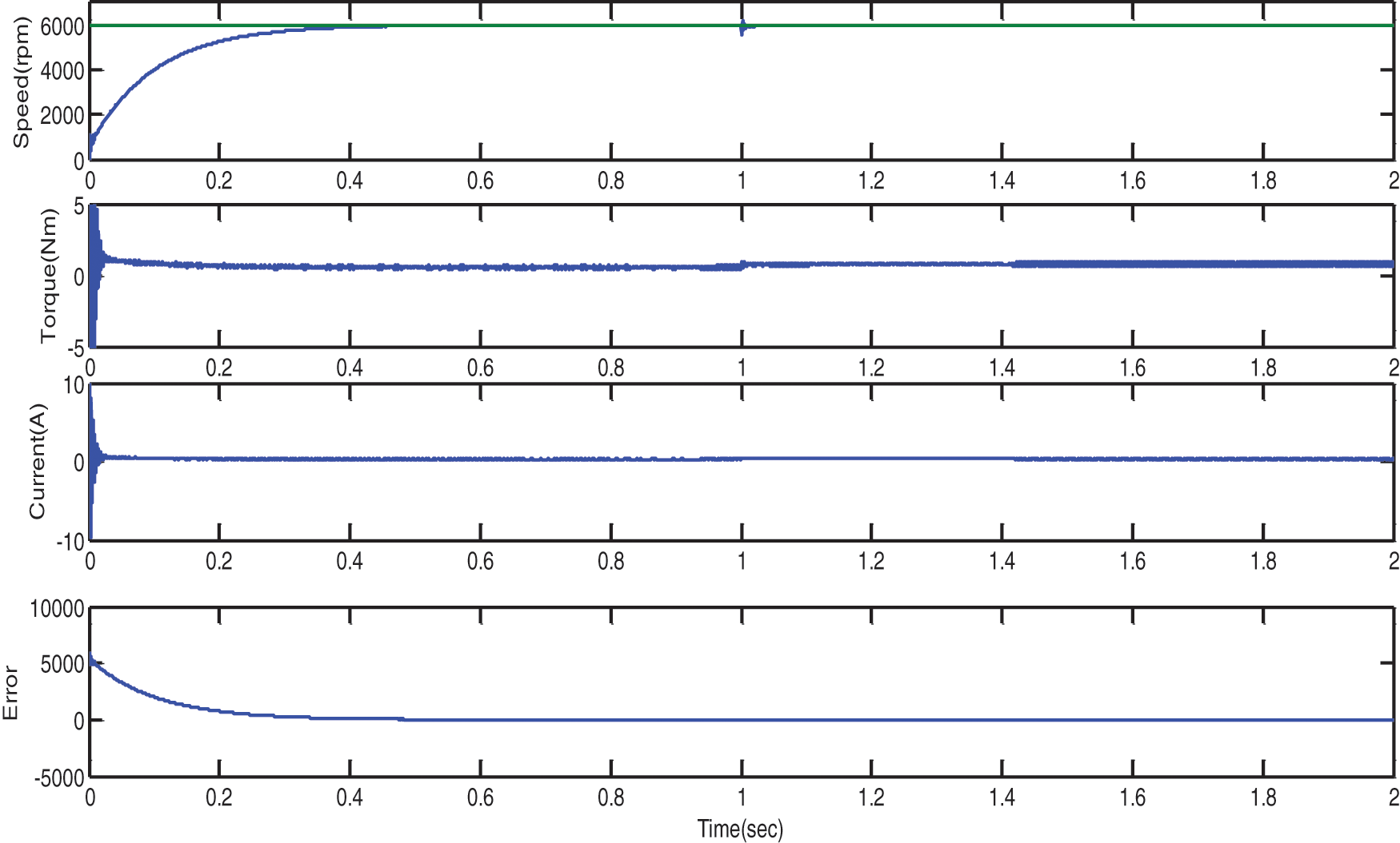
Figure 9: Load variation of PMSM motor from no load to full load- SA
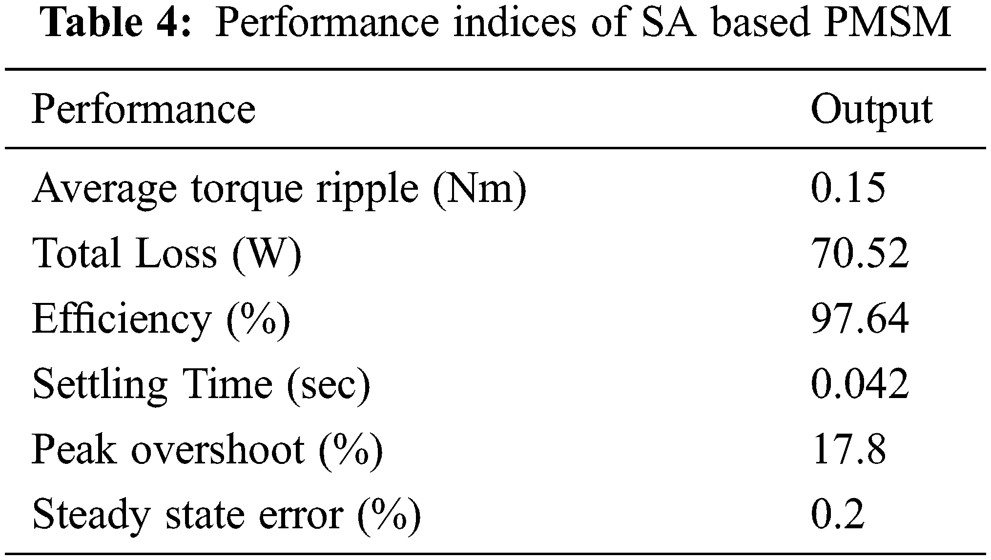
The performance indices of SA based PMSM is shown in Tab. 4. Based on average ripple, losses, efficiency and total harmonic distortion the performance of SA is calculated. The iron loss is maintained as 4 W. The total loss obtained is 70.52 W and the efficiency is 97.64%. The peak overshoot is 17.8% and performance of SA based controller is very efficient than other controller.
For the permanent magnet drive system, this Simulated Annealing technique with reduced THD has been developed. The proposed technique is not only better than conventional methods, but also robust during engine parameters variation, especially when, load torque disturbances are considered. The parameters of DTC controllers for PMSM are automatically adjusted by the optimization algorithm. The advantages of the PI-Fuzzy-SA algorithm are retained when used together. The results show that in all applications, and in particular in this work, the proposed algorithm is very versatile. The outstanding simulation results produced demonstrate the efficacy of this technique in controlling the PMSM speed torque and d and q axes at the present time. It also improves the rate of system convergence. PMSM with low THD is well suited for railway application. This proposed technology satisfies many industrial and railway applications.
Funding Statement: The authors received no specific funding for this study.
Conflicts of Interest: The authors declare that they have no conflicts of interest to report regarding the present study.
1. Y. Wang, Y. Zhu, X. Zhang, B. Tiang and K. Wang, “Anti disturbance sliding mode- based deadbeat direct torque control for PMSm speed regulation Systems,” IEEE Transaction on Transportation Engineering, vol. 4, no. 4, pp. 2705–2714, 2021. [Google Scholar]
2. N. Henini, A. Tlemcani and S. Barket, “Adaptive interval type-2 Fuzzy controller based DTC of PMSM,” Advances in Electrical and Computer Engineering, vol. 21, no. 2, pp. 15–22, 2021. [Google Scholar]
3. R. Eswar, S. Prasad, P. Pradhan, S. Prasad and A. Prasad, “Modified DTC of PMSM drive for electrical vehicle application,” in Proc. of the IEEE Conf. on Madras Section Conf.(MASCON), Chennai, India, pp. 1–5, 2021. [Google Scholar]
4. Z. Jin, X. Sun, G. Lei, Y. Guo and J. Zhu, “Sliding mode DTC of SPMSMs based on a hybrid Wolf optimization algorithm,” IEEE. Transaction on Industrial. Electronics, vol. 69, no. 5, pp. 4534–4544, 2022. [Google Scholar]
5. K. Eshwar and T. V. Kumar, “Reduction of torque and flux ripples in direct torque control for 3-level open end winding PMSM drive,” IET Electric Power Application, vol. 14, no. 14, pp. 2843–2854, 2021. [Google Scholar]
6. A. Rehman, H. Chori and J. W. Jung, “An optimal Direct torque control strategy for surface mounted permanent magnet synchronous motor drives,” IEEE Transaction on Industrial Informatics, vol. 17, no. 11, pp. 7390–7400, 2021. [Google Scholar]
7. B. Shao, Z. Q. Zhu, J. Feng and S. Guo, “Compensation of selective current harmonics for switching table based DTC of Dual 3 phase PMSM Drives,” IEEE Transaction on Industrial Application, vol. 57, no. 3, pp. 2505–2515, 2021. [Google Scholar]
8. G. Sudharsan, A. Santiago and V. Raghunathan, “Fatigue load mitigation in wind turbine using a novel anticipatory predictive control strategy,” Journal of Electrical Engineering, vol. 18, no. 2, pp. 1–17, 2018. [Google Scholar]
9. C. R. Harahap, R. Saito and H. Yamada, “Speed control of Permanent Magnet Synchronous Motor using FPGA for high frequency SIC MOSFET inverter,” Journal of Engineering Science and Technology, pp. 11–20, Special issue, 2014. [Google Scholar]
10. C. Zhou, D. Quach and N. Xiong, “An improved direct Adaptive fuzzy controller of an Uncertain PMSM for web based E-series systems,” IEEE Transaction on Fuzzy Systems, vol. 23, no. 1, pp. 58–71, 2014. [Google Scholar]
11. K. Jash, P. K. Aha and G. K. Panda, “Vector control of permanent magnet synchronous motor based on sinusoidal pulse width modulated inverter with proportional integral controller,” International Journal of Engineering Research and Applications, vol. 3, no. 5, pp. 913– 923, 2013. [Google Scholar]
12. L. Wang and K. Xiao, “PI controller relay auto-tuning using delay and phase margin in PMSM drives,” Chinese Journal of Aeronautics, vol. 27, no. 6, pp. 1527–1537, 2014. [Google Scholar]
13. M. Graf, L. Otava and L. Buchta, “Simple Linearization approach for MPC design for small PMSM with field weakening performance,” Elsevier, vol. 48, no. 4, pp. 159–164, 2015. [Google Scholar]
14. F. M. Fayez and E. Sousy, “Adaptive hybrid control system using a recurrent RBFN-based self- evolving fuzzy-neural-network for PMSM servo drives,” Applied Soft Computing, vol. 21, no. 1, pp. 509–532, 2014. [Google Scholar]
15. D. Xu, S. Zhang and J. Liu, “Very low speed control of PMSM based on EKF estimation with closed loop optimized parameters,” Elsevier, vol. 52, no. 6, pp. 835–843, 2013. [Google Scholar]
16. G. Wang, R. Yang and D. Xu, “DSP-based control of sensorless IPMSM drives for wide-speed-range operation,” IEEE Transaction on Industrial Application, vol. 60, no. 2, pp. 720–727, 2013. [Google Scholar]
17. M. A. Hamida, D. Leon and R. Boisliveau, “An adaptive interconnected observer for sensorless control of PM synchronous motors with online parameter identification,” IEEE Transaction on Industrial Electronics, vol. 60, no. 2, pp. 739–748, 2013. [Google Scholar]
18. H. Zhang, S. Luo, Y. Yu and L. Lingshun, “Study on series control method for dual three-phase PMSM based on space vector pulse width modulation,” International Journal of Control and Automation, vol. 8, no. 1, pp. 197–210, 2015. [Google Scholar]
 | This work is licensed under a Creative Commons Attribution 4.0 International License, which permits unrestricted use, distribution, and reproduction in any medium, provided the original work is properly cited. |