| Journal of Renewable Materials |
DOI: 10.32604/jrm.2021.016262
ARTICLE
Analysis of the Impact Resistance of Photovoltaic Panels Based on the Effective Thickness Method
1College of Architecture and Environment, Sichuan University, Chengdu, 610065, China
2Institute of New Energy and Low-Carbon Technology, Sichuan University, Chengdu, 610207, China
3Suzhou Talesun Solar Technologies Co., Ltd., Suzhou, 215542, China
4Department of Architecture and Built Environment, Faculty of Engineering, University of Nottingham, University Park, Nottingham, NG7 2RD, UK
5National Photovoltaic Product Quality Supervision and Inspection Center, Chengdu, 610065, China
*Corresponding Author: Lingzhi Xie. Email: xielingzhi@scu.edu.cn
Received: 21 February 2021; Accepted: 19 March 2021
Abstract: Based on the recent development of renewable energy utilization technology, in addition to centralized photovoltaic power plants, distributed photovoltaic power generation systems represented by building-integrated photovoltaic systems are frequently employed for power supply. Therefore, in the architectural design, the double-glass photovoltaic module used in the integrated photovoltaic building system puts forward a higher load-bearing capacity requirement and the corresponding simplified method of carrying capacity check. This article focuses on the simplified method of checking the bearing capacity of the four-sided simply supported double-glass photovoltaic module. First, the principle of equivalent stiffness is used to calculate the effective thickness. Then, the rationality of this approach is verified by comparing the bending states of sandwich panels under different shear moduli. The double-glass photovoltaic module is equivalent to a single-layer board, and its effectiveness is verified by comparing the impact test results of the double-glass photovoltaic module with the results of the single-layer board. But the comparison with the test results shows that, from the perspective of architectural design, the effective thickness results in this paper can ensure that the building structure has sufficient bearing capacity, but the four-side simply supported boundary theory cannot fully reflect the calculation of the bearing capacity of the four-side clamped double-glass photovoltaic module.
Keywords: Double-glass photovoltaic module; dynamic stiffness characteristics; natural frequency; effective thickness; impact test
Based on the recent development of renewable energy utilization technology, in addition to centralized photovoltaic power plants, distributed photovoltaic power generation systems represented by building-integrated photovoltaic (BIPV) systems are frequently employed for power supply [1–3]. BIPV systems are an important part of photovoltaic applications [4–5]. Photovoltaic modules are designed to be combined with buildings as building components [6–7] to reduce the cost of building materials while providing additional power for buildings. Therefore, BIPV systems can meet the requirements for green building energy savings, emission reduction, and economic savings and are important development goals for photovoltaic applications [4–5].
In the BIPV system, photovoltaic modules with different packaging materials can be used for different applications. For example, ordinary single-glass photovoltaic modules are usually used on opaque roofs [8]. However, in actual engineering, the photovoltaic modules used in BIPV systems must not only provide electricity for building use but also meet lighting and safety requirements [7–9]. Therefore, BIPV systems often use photovoltaic modules called double-glass photovoltaic modules [8]. Compared with traditional single-glass photovoltaic modules used in centralized photovoltaic power stations, double-glazed photovoltaic modules have better light transmittance. However, BIPV systems can use double-sided double-glazed photovoltaic modules, which will provide more electricity than single-sided double-glazed photovoltaic modules [9–10]. Correspondingly, there have been many corresponding studies on the output power of photovoltaic modules. Premkumar et al. [11–12] analyzed the V-I relationship of the components, proposed a corresponding analysis model, and also studied the power output of the components under different lighting conditions. In the application of the BIPV system, the double-glass photovoltaic module as a component of a building structure needs to bear the corresponding external loads; therefore, the mechanical properties of double-glass photovoltaic modules in BIPV systems must meet the requirements of the mechanical properties of the building. The International Electrotechnical Commission (IEC) specification [13] provides requirements for the design, evaluation and finalization of crystalline photovoltaic modules for ground use. These requirements specify the mechanical load and hail impact mechanical test methods and eligibility criteria used to test the eligibility of crystalline photovoltaic modules, and there is no ongoing research on the mechanical performance parameters of photovoltaic modules. However, the mechanical performance parameters of double-glass photovoltaic modules are crucial to the design of BIPV systems.
The packing structure of a double-glass photovoltaic module is shown in Fig. 1. It consists of two upper and lower surface layers of the glass and an ethylene-vinyl acetate (EVA) copolymer intermediate layer that wraps the silicon cell and the power bus bar [14–18]. The basic structure of double-glass photovoltaic modules is similar to that of laminated glass [16–18]. Naumenko et al. [16] hypothesized that silicon cells would not affect the overall bending of a sheet or the stiffness of a membrane; therefore, in the overall deformation analysis, the entire intermediate layer of the organic polymer covering a silicon cell can be regarded as a homogeneous shear layer. At this time, the mechanical model of a double-glass photovoltaic module is the same as that of a laminated composite glass panel. Mishra [19] reviewed the fracture behavior of laminated composite glass plates and introduced a variety of mechanical models suitable for the theoretical analysis of composite material laminated plates, such as classical lamination theory (CLT), first-order shear deformation theory (FSDT), and layerwise theory (LWT). In recent years, many scholars have extended these theoretical studies to the mechanical behavior of photovoltaic panels. Naumenko et al. [16] used LWT to study the layering of double-glass photovoltaic modules. Li et al. [17] used the Hoff interlayer theoretical model [20] to analyze the bending resistance of double-glazed photovoltaic panels under the boundary conditions of the panel being simply supported on four sides and verified the accuracy of the theory by comparing their results with the results of experiments. In addition, many scholars have used experimental research or numerical simulations to study the response of photovoltaic modules under different boundary conditions and different static forces [21–23]. These studies have greatly promoted the application of photovoltaic modules. However, in BIPV systems, a double-glass photovoltaic module is an integral part of the building structure [7–8]. In addition to bearing quasi-static loads such as wind pressure, a double-pressure photovoltaic module may suffer from impacts due to hail and various flying objects. Therefore, theoretical and experimental research related to the impact effect is also of great significance to the design and application of double-glass photovoltaic modules.
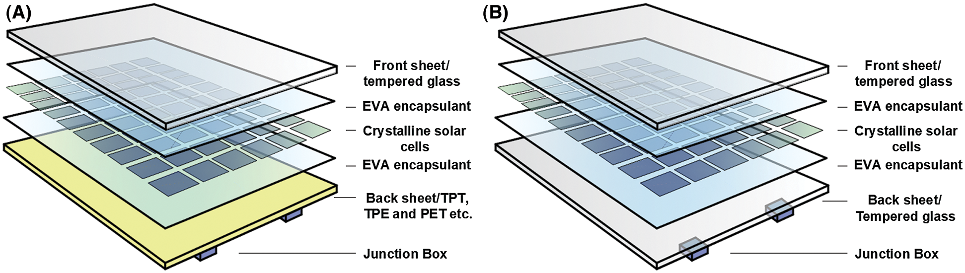
Figure 1: Sandwich panel structure of a crystalline photovoltaic module. (A) Single-glass photovoltaic modules. (B) double-glazed photovoltaic modules
In the analysis of impact and collision for sandwich panels, the key to determining the impact response is to obtain the time history curve of the impact contact force. Many scholars have carried out research on the impact of composite laminates by assuming a certain time history change and distribution of contact forces [24–26]. Karas [27] extended Timoshenko’s method [28] of using local indentation to solve the beam impact response of rectangular simply support plates for the analysis of the center collision problem and verified the accuracy of the method through experiments. From the results of these studies, it is undoubtedly difficult to evaluate the impact bearing capacity if the relevant theories for sandwich structures are directly used to guide the structural design. The concept of effective thickness proposed by Wölfel [29] in 1987 simplifies the calculation of this problem. At present, this method is adopted in the design specifications of laminated glass in China, Europe and the USA [30–32] to simplify the calculation of sheet deformation under bending. In addition, many scholars have studied the optimization method of the effective thickness method of laminates. Peng et al. [33] regarded the middle layer as a rigid material in the research of laminated glass, and combined it with the surface layer to calculate the overall bending rigidity of the structure to obtain an effective thickness method. Calderone et al. [34] uses finite element analysis to analyze the structural performance of laminates, and optimizes the existing effective thickness formula based on the test results. Galuppi et al. [35] proposed a variational method to improve the accuracy of effective thickness calculation on the bending performance of laminated beams. However, the effective thickness methods in these laminated glass design codes all originated from research on the equivalent stiffness of laminated beams. Moreover, the effective thickness method in the Chinese code completely ignores the influence of the shear strength of the intermediate layer [30]. Therefore, these effective thickness methods need to be evaluated to determine if they are suitable for the design calculation of double-glass photovoltaic modules in BIPV systems.
Based on the status of the research results discussed above, this paper uses the effective thickness as an index to explore the impact resistance of a double-glass photovoltaic module in a BIPV system and focuses on the calculation approach based on the effective thickness of a double-glass photovoltaic module. This paper explores the overall stiffness characteristics of a double-glass photovoltaic module through the analysis of the natural frequency under the condition of the simply supported on four sides. The principle of equivalent stiffness is used to calculate the effective thickness. Then, the rationality of the method is verified by analyzing the bending state of sandwich panels under different shear moduli. The double-glass photovoltaic module is equivalent to a single-layer board, and its effectiveness is verified by comparing the impact test results of the double-glass photovoltaic module with those of a single-layer board. Finally, the applicable range of the formula is verified by comparing the effective thickness formulas of European and American standards.
2 Theoretical Analysis of the Effective Thickness
The concept of effective thickness has been applied to the design of sandwich panels and the evaluation of their bearing capacities. In Chinese construction industry standard JGJ113-2015 [30], the effective thickness is taken as
The American standard ASTM E1300 [31] and the European standard PREN 13474 [32] define a shear stress transfer coefficient x that reflects the influence of the shear resistance of the intermediate layer on the effective thickness of the sandwich structure.
where
The effective thickness formula in the Chinese standard regards laminated glass as two laminated plates, and does not consider the contribution of the interlayer film to the bending performance of laminated glass [36]. The effective thickness obtained from European and American standards is obtained through bending analysis of laminated glass beams with a certain width [34–35]. Whether this approach is suitable for double-glass photovoltaic modules in BIPV systems must be verified by further research.
2.1 Basic Assumptions of the Mechanical Model of Double-Glass Photovoltaic Modules
A suitable mechanical model is the basis for a structural theoretical analysis. Based on Reissner’s sandwich theory [37], Hoff [20] proposed that the theory of isotropic sandwich panels considering the bending stiffness of the upper and lower layers can effectively reflect the structural characteristics of photovoltaic panels. Moreover, Li et al. [17] verified the accuracy of Hoff’s theory when analyzing the bending of double-glass photovoltaic modules. To simplify the theoretical analysis of double-glass photovoltaic modules under impact, the following basic assumptions are adopted and combined with the Hoff’s interlayer theoretical model to perform dynamic analysis.
1. As shown in Fig. 2, the thickness of the silicon cell in the double-glass photovoltaic module is very thin, the size is small, and a complete layer cannot be formed in the intermediate layer, which can affect the overall flexural rigidity of the structure. Therefore, the EVA intermediate layer that wraps the silicon cell is regarded as a homogeneous shear layer, and the stress component in the xy plane is ignored.
2. The thickness of the upper and lower panels of a double-glazed photovoltaic module sandwich structure is thicker than the middle layer. However, the thicknesses of the upper and lower surface layers of the glass are still much smaller than the minimum size of the middle surface of the plate, as shown in Fig. 3, so the upper and lower layers are considered ordinary thin plates.
3. In this article, only the effect of the impact load at the center of the plate is studied, and thus, research is conducted on the antisymmetric deformation of the component. Ignoring the strain in the z direction of the intermediate layer, that is assuming that ɛz = 0 and σz = 0 in the intermediate layer according to Hooke’s law.
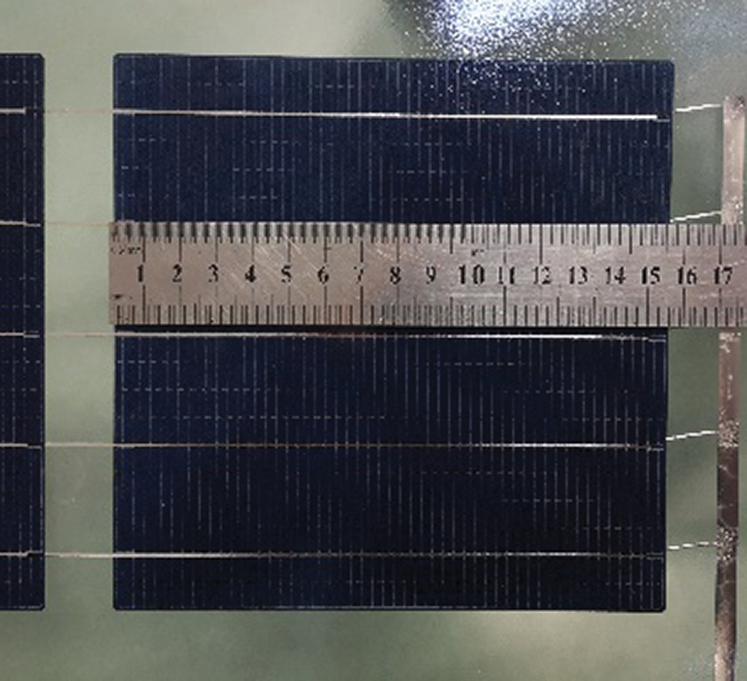
Figure 2: Silicon cells in double-glass photovoltaic modules
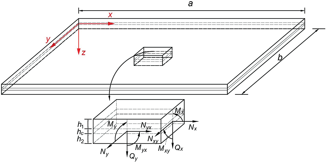
Figure 3: Geometry of the crystalline photovoltaic module and the force state of the parallelepiped unit
2.2 Natural Frequency of the Double-Glass Photovoltaic Module
Fig. 3 shows the forces acting on the basic hexahedral unit of the sandwich panel of the double-glass photovoltaic module, where a and b are the structural dimensions of the plate; h1, h2 and hc are the thicknesses of the upper, lower and middle layers of the double-glass photovoltaic module, respectively; Qx and Qy are the total transverse shear forces of the element in the yz plane and xz plane, respectively; Mx, Myx, My, and Mxy are the total bending moment of the unit in the yz plane, total torque of the unit in the yz plane, total bending moment of the unit in the xz plane and total torque of the unit in the xz plane, respectively; Nx, Ny and Nxy are the preloaded internal forces that may exist in the xy plane of the plate, but the boundary conditions of the four-side-supported double-glass photovoltaic modules in the BIPV system can be regarded as four simply supported sides, so the double-glass photovoltaic modules in the BIPV system do not affected by the internal factors due to preloading.
The overall balance equation of the sandwich structure is the same as that of the single-layer board, and the governing equation of the theoretical sandwich model presented by Hoff [20] is still based on the overall balance equation of the sandwich board. Hoff first discussed the stress components borne by different layers, then used the principle of superposition to obtain the total bending moments Mx and My, total torque Mxy and total transverse shear forces Qx and Qy in the sandwich plate, and then solved the control equations. Therefore, based on the relevant assumptions in 2.1 and combined with the Hoff’s interlayer theoretical model, the lateral vibration control equation of the crystalline photovoltaic module can be obtained
From this, the lateral vibration control equation expressed by
The photovoltaic modules in the BIPV system are usually installed in four-side clamp support, which can be simplified to four-side simple support. Therefore, the boundary conditions of the component can be obtained as
Same as the simple supported four-sided single-layer board, the modal function satisfying Eq. (9) can be set as
Simultaneous Eqs. (10) and (8) the natural frequency
2.3 Effective Thickness of the Double-Glass Photovoltaic Module
In the vibration analysis of thin plates [39], the natural frequency ωmn corresponding to the (m, n)-order mode of a single-layer plate under the boundary condition of being simply supported on four sides can be expressed as
Let Iw = (hc + h1)2h1 + (hc + h2)2h2, then Eq. (14) can be simplified as
Parameter η is introduced as
The theoretical solution for the effective thickness of the double-glass photovoltaic module can be obtained as
Comparing Eq. (2) to Eq. (15), the effective thickness method obtained by the sandwich plate theory in this paper and the effective thickness method obtained by the sandwich beam theory in European and American standards both consider the influence of the shear strength of the soft sandwich interlayer on the effective thickness. However, the effective thickness methods in the European and American standards only include the influence of the long side of the sheet structure size, which cannot reflect the difference in the effective thickness of sandwich structures with different structure sizes. In contrast, the effective thickness method obtained in this paper can compensate for this deficiency.
3.1 Verification of the Validity of the Model
For the different shear moduli of the middle layer, the sandwich structure will show different bending states when deformed under forces [36]. As shown in Fig. 4, when the shear modulus of the intermediate layer is sufficiently large, the sandwich panel can be regarded as a single-layer panel with a constant nominal thickness. The bending state at this time corresponds to situation (a). When the shear modulus of the middle layer is sufficiently small, the load-bearing effect of the middle layer can be ignored. The sandwich panel can be regarded as two surface panels that are simply stacked together. The bending state at this time corresponds to situation (c). However, in actual engineering scenarios, the bending state of double-glass photovoltaic modules is closer to that of situation (b), and the shear resistance of EVA cannot be ignored, but its strength is still limited compared to that of the surface glass.
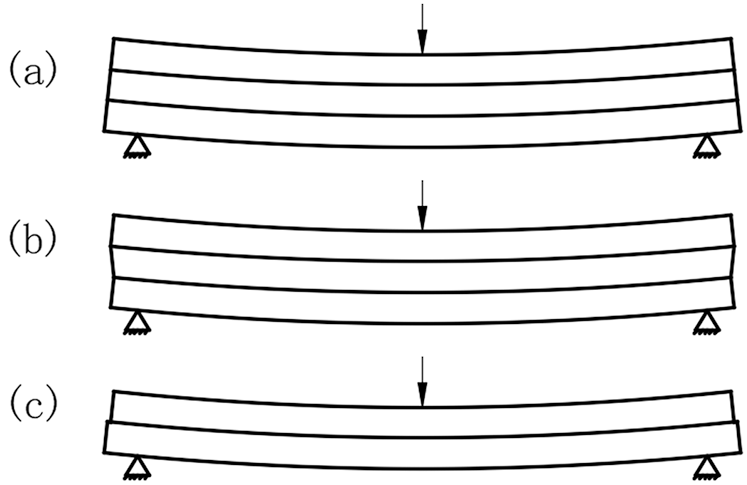
Figure 4: Bending state of a sandwich structure with different interlayer shear modulus (a) Interlayer shear modulus Gc → 0. (b) Interlayer shear modulus Gc > 0. (c) Interlayer shear modulus Gc → ∞ [36]
This section will verify the validity of the formula by comparing the effective thickness and natural frequency of the double-glass photovoltaic module under different ultimate shear moduli with the thickness and natural frequency under the three bending states. Analyzing the value of the shear modulus in Eq. (15), it is evident that when the interlayer shear modulus Gc → 0, η = 0; when the interlayer shear modulus Gc → ∞, η = 1. By combining this result with Eq. (16), when the interlayer shear modulus Gc → 0, the effective thickness of the double-glass photovoltaic module is
The thicknesses of the upper and lower layers in the double-glass photovoltaic module are usually the same. When a different value is selected for this thickness, the effective thickness obtained according to the condition where Gc → ∞ will be compared with the nominal thickness of the sheet, as shown in Tab. 1.
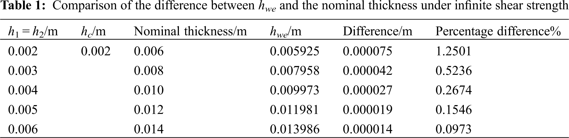
The percentage Difference shows that when the interlayer shear modulus Gc → ∞, the difference between the effective thickness obtained in this paper and the nominal thickness of the double-glass photovoltaic module is almost negligible, which satisfies situation (a) in Fig. 4. From this result, it is evident that the value of the shear modulus has a great influence on the effective thickness, and when the shear modulus is the limit value, the effective thickness of the double-glass photovoltaic module conforms to the bending state of the sandwich structure under the same conditions.
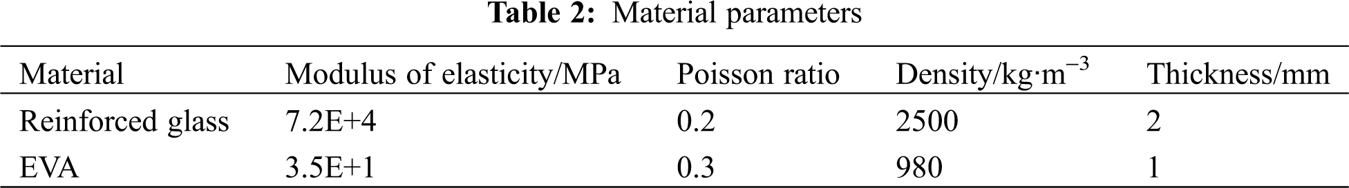
To better present the actual mechanical properties of the double-glass photovoltaic module in the BIPV system under impact, this paper uses the commercial double-glass photovoltaic modules provided by Zhongli Teng-hui Photovoltaic Technology Co., Ltd., for testing, as shown in Fig. 5. The relevant material parameters for the 3 test components are shown in Tab. 2, and the structural size of the double-glass photovoltaic module is 1658 mm × 992 mm. Based on the impact of different heights, the changes in the deflection of the plates under different energy impacts are explored.
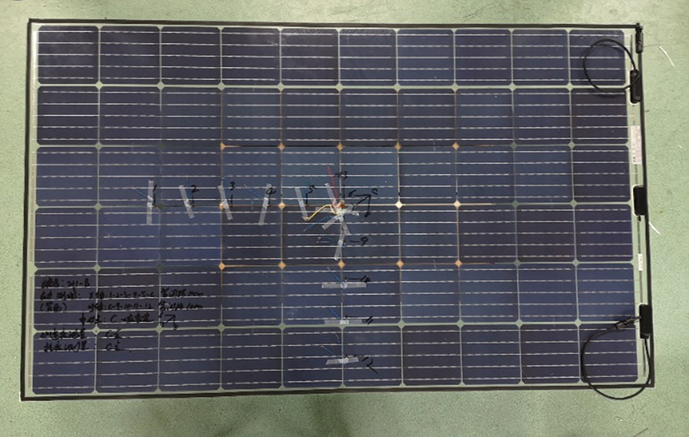
Figure 5: Commercial double-glass photovoltaic modules
With reference to the test method in the current IEC specification [11], a test stand that can impose boundary conditions similar to those of actual working conditions is designed, as shown in Fig. 6. The impact load is provided by steel balls controlled by the positioning device of the outer frame. The 1A531E acceleration sensor provided by Jiangsu Donghua Testing Technology Company is used for acceleration measurement, and the DH8302 dynamic signal test and analysis system is used for data collection. The sampling frequency is 1 MHz. The CD22-100VM12 laser displacement meter provided by the Japanese company, OPTEX, is used for deflection measurement, and the dynamic signal test and analysis system DH5922D provided by Jiangsu Donghua Testing Technology Company is used for data collection. The sampling frequency is 200 kHz.
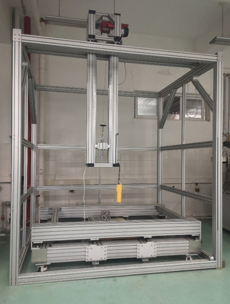
Figure 6: Test device
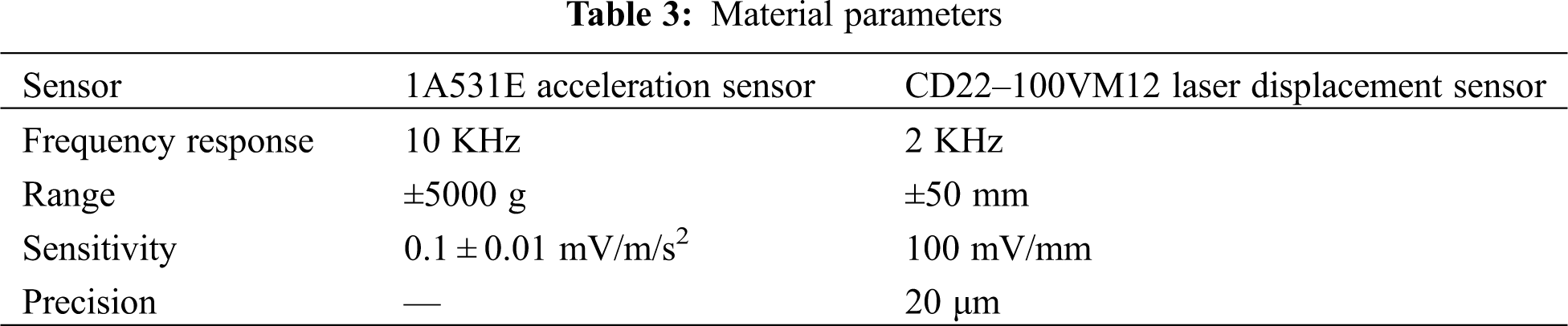
The simplified test process is shown in Fig. 7. The 1A531E acceleration sensor is placed on the impactor to test the acceleration change of the impactor during contact.The CD22-100VM12 laser displacement sensor is placed directly below the specimen to test the lateral displacement of the impact point of the specimen. The relevant parameters of the sensor are shown in Tab. 3.
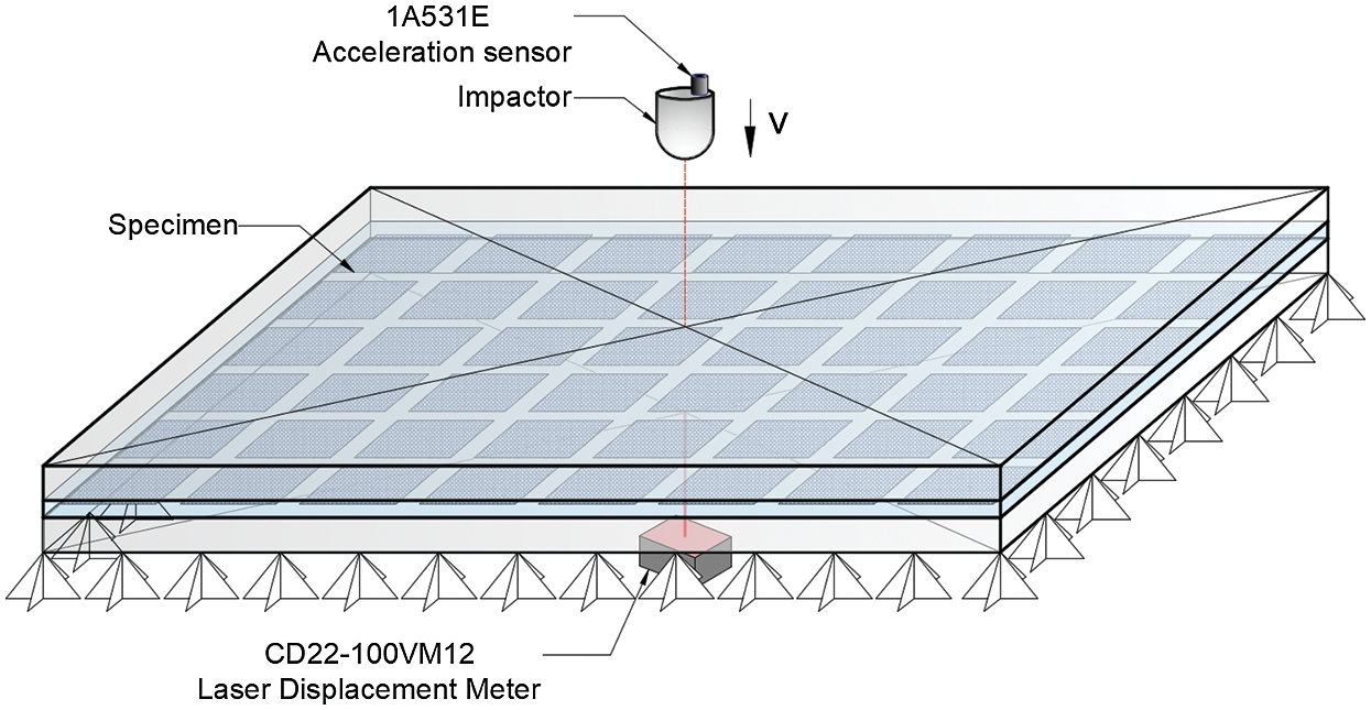
Figure 7: Test diagram
3.2.2 Deflection Verification and Discussion
In this section, the effective thickness method presented in Section 2.4 will be used to equate the double-glass photovoltaic module to a single-layer structure, and then the law of conservation of energy will be used to determine the change in the deflection of the equivalent single-layer plate under different potential energy impacts. To use the law of conservation of energy, it is first necessary to fully understand the energy transfer between the steel ball and the plate during the impact contact process. Based on work by Timoshenko [28], using local indentation to solve the beam impact response method, and combining the result with the research results obtained by Karas [27], the equivalent single-layer plate impact contact force time history curve and plate deflection time history curve can be obtained. The initial kinetic energy Ek of the plate during the impact contact process can be obtained by integration; an equation can be established to solve for the maximum deflection of the equivalent single-layer plate under impact based on the strain energy of the plate at the moment of maximum deflection. Then, the results obtained by the calculation can be compared to the test results.
In the ball-plate impact problem, the contact area is circular, and the contact force f is calculated as [40]
MATLAB software program is used to numerically solve Eq. (22), and the time history curve of the impact contact force and the maximum value Ek of the kinetic energy transmitted to the plate by the impact is obtained. Taking the impact height of 0.5 m as an example, the comparison with the result of the impact contact force in the test is shown in Fig. 7.
The thickness of the equivalent single-layer board is still much smaller than the minimum dimension b of the middle surface of the plate, so this single-layer board is regarded as an ordinary thin plate for analysis. Glass is a typical elastic and brittle material, and its mechanical properties basically conform to Hook Hooke’s law [41]. Therefore, according to the basic assumption of the small deflection bending theory of thin plate, the strain energy [39] of a thin plate with a constant thickness at maximum deflection under the boundary conditions of being simply supported on all sides can be expressed as
According to the law of conservation of energy
Ek can be expanded by a double series
Eqs. (24) and (25) can be simultaneously solved to obtain
Therefore, the maximum deflection of the double-glass photovoltaic module at the impact point (a/2, b/2) under the impact of the falling ball is
The maximum deflection of the double-glass photovoltaic module under impact at different heights measured by the test is compared with the theoretical solution of the equivalent single-layer board deflection, as shown in Fig. 8.
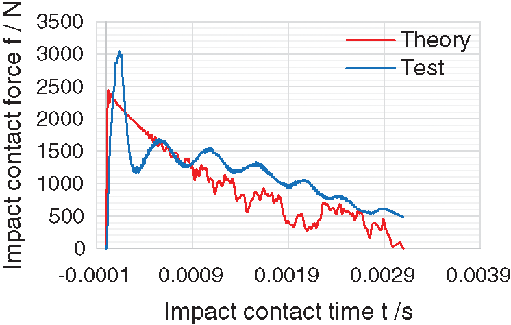
Figure 8: Comparison of the time history curves of impact contact force
Fig. 8 shows that the time history curve of the impact contact force measured by the experiment has the same trend as the theoretical result. In a very short contact time during impact, the impact contact force will reach the maximum value, and then it will decrease to zero with a certain fluctuation trend in a relatively long duration time.
However, the maximum value of the theoretically calculated impact contact force is smaller than the experimental value, which is due to the four-sided simply supported boundary conditions adopted in the theoretical assumption. In the actual BIPV project, to prevent the edges and corners of the tempered glass from being damaged by strong extrusion, elastic materials such as rubber pads with supported edges will be added. Therefore, the boundary conditions of double-glass photovoltaic modules are actually closer to hose of the four-sided elastic support condition. However, the four-sided elastic support introduces very complicated boundary conditions. To date, a reasonable vibration mode has not been proposed. In theory, the boundary condition can be equivalent to the conservative four-sided simply supported boundary condition. Under the same impact, the lateral displacement of the four-sided elastic support plate is smaller than that of the four-sided simply supported boundary condition. Therefore, the theoretically calculated value of indentation is smaller than that in the actual situation, and the calculated maximum impact force of the plate will also be smaller than that in the actual situation. However, this meets the architectural design requirements for safety.
In addition, the two curves have different fluctuation characteristics during the time period of contact force decline. Theoretically, by adjusting the calculation parameters in MATLAB software, it is found that the obvious fluctuation of the curve in the descending stage is related to the number of modes accumulated during the calculation. Through the analysis of the period of the curve fluctuation of the descending section, combined with the free vibration of the damped single degree-of-freedom system, it can be proven that the regular fluctuation of the curve in the descending section of the test is caused by the influence of the plate’s own damping.
Fig. 9 shows that the theoretical value of the maximum deflection of the plate under the impact of different heights and the test results of the same steel ball show power changes with height, which shows that the method of calculating deflection using the principle of conservation of energy is feasible in this paper. However, it is obvious that in the theoretical analysis, when the clamped support boundary is simplified to four sides simply supported, the maximum deflection solution of the component under impact is greater than the experimental result. From the perspective of architectural design, this result can ensure that the building structure has sufficient bearing capacity; but in fact, it shows that the true bending stiffness of double-glass photovoltaic modules has not been fully considered.
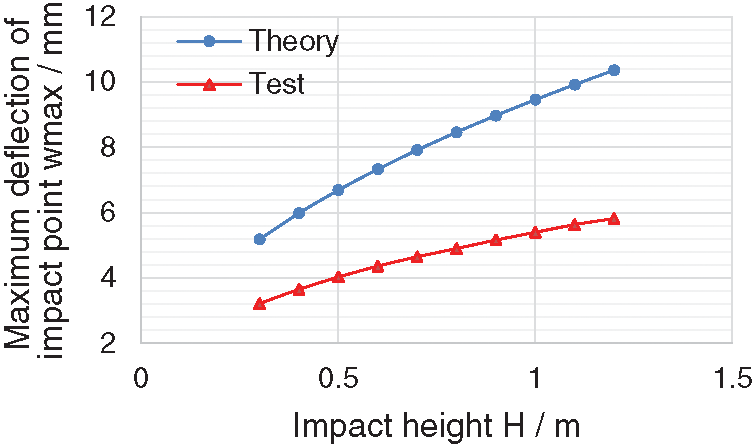
Figure 9: Maximum deflection of the impact point under different impact heights
4 Comparison with Existing Formulas
It can be seen from Fig. 10 that when the interlayer shear modulus is concentrated in the range of 0∼35 MPa, it has a great influence on the effective thickness of the dual-glass photovoltaic module. When the interlayer shear modulus exceeds 35 MPa, the curve will become flat. Most of the double-glass photovoltaic modules in actual projects use EVA material as the intermediate layer material, and the shear modulus of EVA is about 13.5 MPa. The effective thickness thus obtained conforms to the law between the effective thickness and the shear modulus of the intermediate layer shown in Tab. 1.
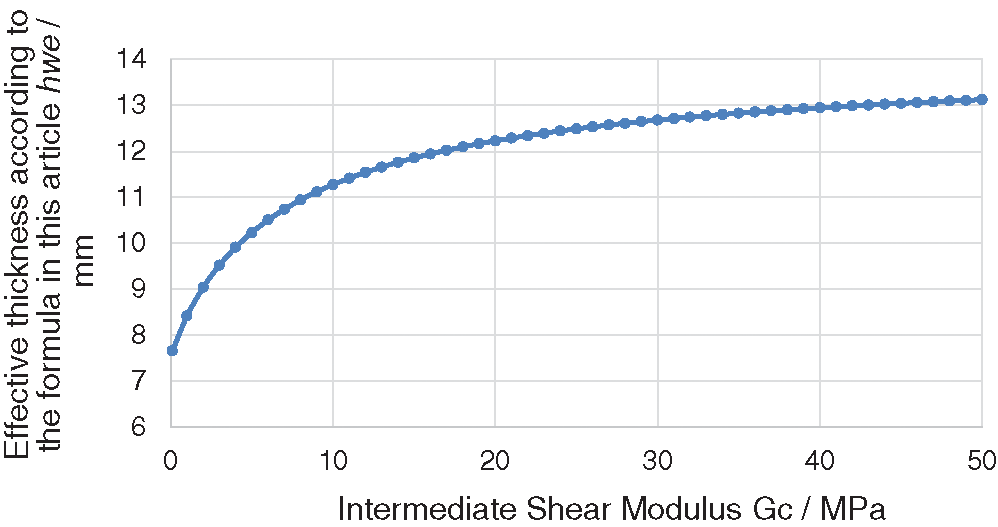
Figure 10: The relationship curve between the effective thickness of the photovoltaic module (6 mm + 2 mm + 6 mm) and the shear modulus of the intermediate layer
As described in Section 2 of this article, European and American standards [29–30] have proposed an effective thickness suitable for laminated glass in the bending analysis of laminated glass beams with a certain width. However, whether this thickness is suitable for dual-glass photovoltaic modules must be further verified. This section compares the effective thickness hwe obtained in this paper with the effective thickness he in European and American standards to verify the scope of application of the formula in this paper and whether it meets the safety considerations for sandwich structures (Difference = he − hwe, and Percentage difference = Difference/he).
As shown in Fig. 11, the double-glass photovoltaic module with a surface layer thickness of h1 = h2 = 6 mm and an intermediate layer thickness of hc = 2 mm is taken as an example to compare the values of the formula in this paper and the various thicknesses obtained by the equivalent thickness method based on the standards in Europe and the United States. The relevant material parameters are shown in Tab. 2.
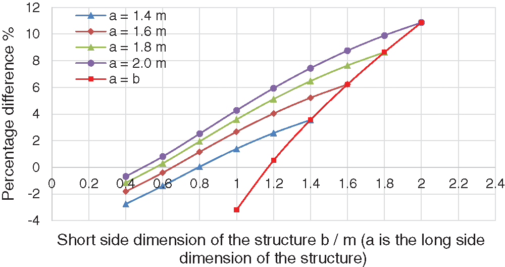
Figure 11: Percentage of the difference in the effective thickness under different combinations of structure sizes (
The curve where a = b shows that for a square double-glass photovoltaic module, when the size is 1.17 m, the effective thickness obtained by the formula in this paper is the same as that in European and American standards. As the size increases, compared with the formula in European and American standards, the formula in this article will be more in line with safety considerations; when the size reaches 1.5 m, the difference between the two formulas will exceed 5%. Other curves show that for nonrectangular double-glass photovoltaic modules with a long side dimension greater than 1.5 m, as the short side dimension of the structure increases, the percentage difference between the two types also increases. Before the short side dimension reaches the limit (when a = 1.6 m and b = 1.4 m; a = 1.8 m and b = 1.2 m; and a = 2.0 m and b = 1.1 m), the percent difference will not exceed ±5%; however, after the short side dimension reaches a certain limit, the percent difference will exceed 5%.
It can be determined that for a double-glass photovoltaic module with a surface layer thickness of
As shown in Fig. 12, further data analysis is carried out on the 1.5 m × 1.5 m double-glass photovoltaic module and compared with the results of previous conclusions. The percent difference shows that for a double-glass photovoltaic module with a fixed structure dimension, the percent difference of the two formulas increases with the increase in the thickness of the surface layer or the thickness of the intermediate layer. The red points in the figure are the working conditions considered in the previous data analysis. With reference to Fig. 9, it is evident that the limit of the long side dimension and the limit of the corresponding sheet area in the law obtained above are affected by the thickness of the surface layer and the thickness of the intermediate layer of the selected dual-glass photovoltaic module. When the thickness of the middle layer is constant, as the thickness of the surface layer increases, the limit of the long side dimension and the limit of the corresponding sheet area will decrease, and vice versa. When the thickness of the upper and lower layers remains unchanged, as the thickness of the middle layer decreases, the limit of the long side dimension and the limit of the corresponding sheet area will increase, and vice versa. In actual BIPV system engineering applications, when a double-glass photovoltaic module with a relatively large area size is used, the thickness of the glass layer and the intermediate layer is also correspondingly increased according to the requirements of the specification to meet the safety requirements. The formula in this article is more in line with the safety considerations of this type of board than the formulas in the standards.
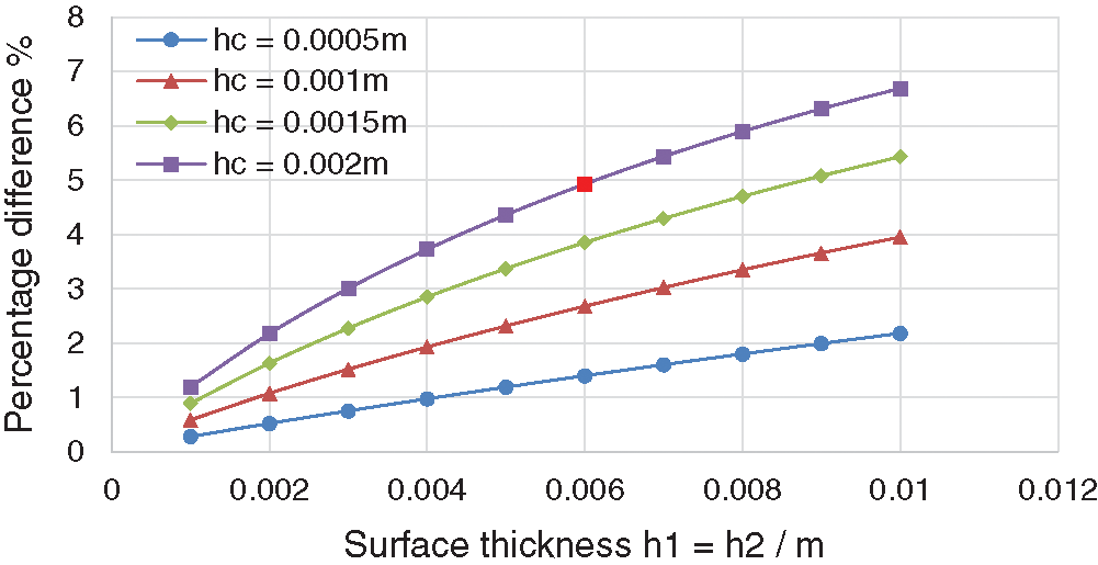
Figure 12: Percentage difference under different thickness combinations of double-glass photovoltaic modules with dimensions of 1.5 m × 1.5 m
To propose an effective thickness formula, whether the formula satisfies the safety consideration of the sandwich structure must first be considered. However, if the effective thickness formula pursues excessive safety, such as the Chinese Building Glass Regulations JGJ113-2015 [28], the design may cause unnecessary material waste. The effective thickness should be the result of the comprehensive consideration of security and economy. Combined with the previous analysis, in the BIPV system application of double-glass photovoltaic modules, the formula obtained in this paper is more in line with safety considerations than the European and American standards [29–30]. On the one hand, the safety requirements of the structure design can be ensured, and on the other hand, the protection of the silicon cell and bus bar welding points in the double-glass photovoltaic module can be effectively improved. At the same time, compared with the Chinese standard, the effective thickness obtained by the formula in this paper is closer to that of the actual situation, which minimizes the quantity of wasted materials and satisfies the economical requirements.
This paper studies the effective thickness method of double-glass photovoltaic modules under four simply supported boundary conditions and the dynamic response of double-glass photovoltaic modules under impact. The experimental and theoretical work has been completed in this article, and this research can lay the foundation for safety requirements for the design of double-glass photovoltaic modules in the future. The following conclusions can be drawn based on the research results.
In this paper, the Hoff model, which is suitable for soft core laminates, is used to describe the stiffness characteristics of double-glass photovoltaic modules under the four-sided simply supported boundary condition. According to the natural frequency equation of the double-glass photovoltaic module and the principle of equivalent stiffness, a calculation of the effective thickness suitable for both photovoltaic modules is obtained.
In the experimental work, referring to the test method in the current IEC specification [11], a platform suitable for tests on the impact of a ball falling on plates of various sizes was designed. The electromagnet and laser positioning device can strictly control the falling point of the steel ball to ensure the accuracy of the test results.
The test results show that when photovoltaic panels are subjected to impact, the entire impact process can be divided into two processes: 1. The contact process between the steel ball and the plate for the forced vibration process of the plate; 2. The free vibration process of the plate after the steel ball and the plate are separated.
This paper uses Timoshenko’s method of using local indentation to solve the impact response of the beam to determine the impact contact force of the photovoltaic panel during impact. In this solution process, the double-glass photovoltaic module is equivalent to a single-layer board according to the effective thickness formula in this paper. The comparison with the experimental results verifies the feasibility of using local indentation to solve the impact response of double-glass photovoltaic modules and verifies the effectiveness of the effective thickness method to simplify the process.
This paper uses the principle of energy conservation to determine the maximum deflection of a plate under impact. In this solution process, the double-glass photovoltaic module is equivalent to a single-layer board according to the effective thickness formula in this paper. Based on a comparison of the test results, it is confirmed that only part of the potential energy of the steel ball is converted into the internal energy of the plate during impact; therefore, determining the ratio of the dissipated energy is very important for accurately solving the deflection response of the plate under impact. At the same time, the results also verify the effectiveness of the effective thickness method for simplifying this process.
Through the comparison with the effective thickness method in European and American standards, the scope of application of the effective thickness method in this paper and the differences between the effective thickness methods in European and American standards are discussed. For double-glass photovoltaic modules with a larger area used in the BIPV system, the effective thickness method adopted in this paper is more in line with the safety considerations of the design. At the same time, compared with the method in Chinese standards, the effective thickness method in this paper is more in line with the economic considerations of architectural design.
The four-side simply supported boundary theory cannot fully reflect the calculation of the bearing capacity of the four-side clamped double-glass photovoltaic module, and more accurate results need to be further studied.
Acknowledgement: The authors are grateful for the financial support from the Ministry of Science and Technology of the People’s Republic of China: Newton Fund-China-UK Research and Innovations Bridges (No. 2016YFE0124500).
Funding Statement: This research was funded by the National Key Research and Development Program of China: Newton Fund-China-UK Research and Innovations Bridges (No. 2016YFE0124500).
Conflicts of Interest: The authors declare that they have no conflicts of interest to report regarding the present study.
1. Michael, E., Mohamed, E. A., David, H. (2019). Renewables 2019: Global status report. USA: Environmental Policy Collection. [Google Scholar]
2. Jger, W. A. (2019). PV status report 2019. European Union: Publications Office of the European Union. [Google Scholar]
3. Outlook B. P. E. (2016). Energy outlook 2016. EK: Energetika. [Google Scholar]
4. Gholami, H., Harald, N. R. (2020). Economic analysis of BIPV systems as a building envelope material for building skins in Europe. Energy, 117931. DOI 10.1016/j.energy.2020.117931. [Google Scholar] [CrossRef]
5. Pagliaro, M., Palmisano, G., Ciriminna, R. (2010). BIPV: Merging the photovoltaic with the construction industry. Progress in Photovoltaics Research & Applications, 181, 61–72. DOI 10.1002/pip.920. [Google Scholar] [CrossRef]
6. Tengyuan, Z. (2020). Study on bending problem of silicon solar cell module: China: Sichuan University. [Google Scholar]
7. Saretta, E., Frontini, F., Bonomo, P. (2016). Laminated BIPV glass: Approaches for the integration in the building skin. Engineered Transparency 2016: Glass in Architecture and Structural Engineering Engineered Transparency. [Google Scholar]
8. Chen, Y., Galal, K., Athienitis, A. K. (2010). Modeling, design and thermal performance of a bipv/t system thermally coupled with a ventilated concrete slab in a low energy solar house: Part 2, ventilated concrete slab. Solar Energy, 84(11), 1908–1919. DOI 10.1016/j.solener.2010.06.012. [Google Scholar] [CrossRef]
9. Kamel, R., Ekrami, N., Dash, P., Fung, A., Hailu, G. et al. (2015). BIPV/T+ASHP: Technologies for nzebs-sciencedirect. Energy Procedia, 78, 424–429. DOI 10.1016/j.egypro.2015.11.687. [Google Scholar] [CrossRef]
10. Wu, X. L., Den, X. Y., Wei, C. G. (2012). The application of insulated double-glass photovoltaic module in BIPV. Advanced Materials Research, 575, 132–136. DOI 10.4028/www.scientific.net/AMR.575.132. [Google Scholar] [CrossRef]
11. Premkumar, M., Kumar, C., Sowmya, R. (2020). Mathematical modelling of solar photovoltaic cell/Panel/Array based on the physical parameters from the manufacturer’s datasheet. Renewable Energy for Development, 9(1), 7–22. DOI 10.14710/ijred.9.1.7-22. [Google Scholar] [CrossRef]
12. Premkumar, M., Subramaniam, U., Babu, T. S., Elavarasan, R. M., Mihet-Popa, L. (2020). Evaluation of mathematical model to characterize the performance of conventional and hybrid PV array topologies under static and dynamic shading patterns. Energies, 13. DOI 10.3390/en13123216. [Google Scholar] [CrossRef]
13. IEC 61215. (2005). Crystalline silicon terrestrial (PV) modules–Designqualification and type approval. USA: International Standard. [Google Scholar]
14. Wang, S., Sun, X., Wang, S. (2016). Double-glass photovoltaic module. United States. Shenzhen BYD Auto R&D Company Limited (Shenzhen, Guangdong, CNBYD Company Limited (Shenzhen, Guangdong, CN) 20160315581. https://www.freepatentsonline.com/y2016/0315581.html. [Google Scholar]
15. Chen, J., Xu, J., Yao, X., Xu, X., Liu, B. et al. (2014). Different driving mechanisms of in-plane cracking on two brittle layers of laminated glass. International Journal of Impact Engineering, 69(7), 80–85. DOI 10.1016/j.ijimpeng.2014.02.014. [Google Scholar] [CrossRef]
16. Naumenko, K., Eremeyev, V. A. (2014). A layer-wise theory for laminated glass and photovoltaic panels. Composite Structures, 112(6), 283–291. DOI 10.1016/j.compstruct.2014.02.009. [Google Scholar] [CrossRef]
17. Li, Y. X., Xie, L. Z., Zhang, T. Y., Wu, Y. P., Sun, Y. Y. et al. (2019). Mechanical analysis of photovoltaic panels with various boundary condition. IOP Conference Series: Materials Science and Engineering, 556(1), 012048 (6pp). DOI 10.1016/j.renene.2019.05.121. [Google Scholar] [CrossRef]
18. Zhang, T. Y., Xie, L. Z., Li, Y. X., Tapas, K. M., Wei, Q. Z. et al. (2018). Experimental and theoretical research on bending behavior of photovoltaic panels with a special boundary condition. Energies, 11, 3435. DOI 10.3390/en11123435. [Google Scholar] [CrossRef]
19. Mishra, A. (2017). Laminated plate theories and fracture of laminated glass plate—A review. Engineering Fracture Mechanics, 186, 316–330. DOI 10.1016/j.engfracmech.2017.10.020. [Google Scholar] [CrossRef]
20. Hoff, N. J. (1950). Bending and buckling of rectangular sandwich plates. Technical Report Archive & Image Library. DOI 10.1007/BF00412000. [Google Scholar] [CrossRef]
21. Hartley, J. Y., Owen, B. M., Truman, T., Maes, A., Elce, E. et al. (2020). Effects of photovoltaic module materials and design on module deformation under load. IEEE Journal of Photovoltaics, 10(3), 838–843. DOI 10.1109/JPHOTOV.2020.2971139. [Google Scholar] [CrossRef]
22. Schulze, S. H., Pander, M., Naumenko, K., Altenbach, H. (2012). Analysis of laminated glass beams for photovoltaic applications. International Journal of Solids & Structures, 49(15–16), 2027–2036. DOI 10.1016/j.ijsolstr.2012.03.028. [Google Scholar] [CrossRef]
23. Paggi, M., Kajari, S. S., Eitner, U. (2011). Thermomechanical deformations in photovoltaic laminates. The Journal of Strain Analysis for Engineering Design, 46(8), 772–782. DOI 10.1177/0309324711421722. [Google Scholar] [CrossRef]
24. Chow, T. S. (1971). On the propagation of flexural waves in an orthotropic laminated plate and its response to an impulsive load. Journal of Composite Materials, 5(3), 306–319. DOI 10.1177/002199837100500302. [Google Scholar] [CrossRef]
25. Sun, C. T., Grady, J. E. (1988). Dynamic deiamination fracture toughness of a graphite/epoxy laminate under impact. Composite Science and Technology, 31, 55–72. DOI 10.1016/0266-3538(88)90077-2. [Google Scholar] [CrossRef]
26. Ramkumar, R. L., Thakar, Y. R. (1987). Dynamic response of curved laminatedplates subjected to low velocity impact. Journal of Engineering Materials & Technology, 109(1), 67. DOI 10.1115/1.3225936. [Google Scholar] [CrossRef]
27. Karas, K. (1939). Platten unter seitlichem Stoss. Ingenieur-Archiv, 10(4), 237–250. DOI 10.1007/BF02084907. [Google Scholar] [CrossRef]
28. Timoshenko, S. P. (1913). Zur frage nach der wirkung eines stosses auf einen balken. Zeitschrift für Mathematik und Physik, 62, 198–209. [Google Scholar]
29. Wölfel, E. (1987). Nachgiebiger verbund eine näherungslösung und deren anwendungsmöglichkeiten. Stahlbau, 6, 173–180. [Google Scholar]
30. China Academy of Building Research (2015). JGJ113-2015 Technical Regulations for Architectural Glass Application. China: China Building Industry Press. [Google Scholar]
31. American Society Testing Materials (2012). E1300-12a. Standard practice for determining load resistance of glass in buildings. USA: American Society for Testing and Materials International. [Google Scholar]
32. CEN-TC129WG8. prEN 13474 (2012). Glass in building–determination of the strength of glass panes by calculation and testing. European: Project of European Standard under Enquiry. [Google Scholar]
33. Peng, Y., Yang, J., Deck, C., Willinger, R. (2013). Finite element modeling of crash test behavior for windshield laminated glass. International Journal of Impact Engineering, 57, 27–35. DOI 10.1016/j.ijimpeng.2013.01.010. [Google Scholar] [CrossRef]
34. Calderone, I., Davies, P. S., Bennison, S. J., Xiao, K. H., Gang, L. (2009). Effective laminate thickness for the design of laminated glass. Glas, 1–5. [Google Scholar]
35. Galuppi, L., Royer, C. G. F. (2012). Effective thickness of laminated glass beams: New expression via a variational approach. Engineering Structures, 38(5), 53–67. DOI 10.1016/j.engstruct.2011.12.039. [Google Scholar] [CrossRef]
36. Shihong, P. (2009). Study on equivalent thickness of laminated glass. Beijing: China General Research Institute of Building Materials Science. [Google Scholar]
37. Reissner, E. (1947). On bending of elastic plates. Quarterly Applied Mathematics, 5(1), 55–68. DOI 10.1002/cpa.3160010403. [Google Scholar] [CrossRef]
38. Research Institute of Mechanics (1977). Bending, stability and vibration of sandwich plate and shell. Beijing: Chinese Academy of Sciences. [Google Scholar]
39. Xu, Z. L. (2016). The fifth edition of elastic mechanics, Vol. 2. Beijing: Higher Education Press. [Google Scholar]
40. Abrate, S. (1991). Impact on laminated composite materials. Applied Mechanics Reviews, 44(4), 155–190. DOI 10.1115/1.3119500. [Google Scholar] [CrossRef]
41. Minakov, A. G. (1961). Glass technology. Glass & Ceramics, 18(3), 165–166. DOI 10.1007/BF00668500. [Google Scholar] [CrossRef]
 | This work is licensed under a Creative Commons Attribution 4.0 International License, which permits unrestricted use, distribution, and reproduction in any medium, provided the original work is properly cited. |