| Journal of Renewable Materials |
DOI: 10.32604/jrm.2021.016118
ARTICLE
Pull-out Behaviour of Axially Loaded Screwed-in Threaded Rods Embedded in CLT Elements: Experimental Study
1Nanjing Tech University, Nanjing, 211816, China
2Southeast University, Nanjing, 211189, China
3Sanjiang University, Nanjing, 210012, China
*Corresponding Author: Huifeng Yang. Email: hfyang@njtech.edu.cn
Received: 08 February 2021; Accepted: 03 March 2021
Abstract: Experimental investigation on the pull-out behaviour, including the withdrawal capacity, slip stiffness and interfacial shear stress, of axially loaded screwed-in threaded rod embedded in cross laminated timber (CLT) was conducted. Specimens with varying embedment length and different number of threaded rods were tested in this study. To prevent premature splitting failure of timber, some specimens were reinforced in the direction perpendicular to the timber grain with self-tapping screws. Test results showed that the screwed-in threaded rod connections exhibited good pull-out behaviour with high withdrawal capacity and slip stiffness. Within a certain range, the withdrawal capacity increases considerably with the increase of embedment length, while the average interfacial shear stress shows the opposite tendency. The self-tapping screws played an important role on reducing the splitting of the timber and improving the withdrawal capacity and slip stiffness of the screwed-in threaded rod. Additionally, for the specimens with self-tapping screw reinforcements, the improvement of withdrawal capacity and stiffness when increasing the number of threaded rods are much more obvious than that of the specimens without the self-tapping screws, due to the change of failure modes.
Keywords: Threaded rods; screwed-in; pull-out behaviour; timber structure; experimental study
Dowel-type connections are the most common type of connection in timber structures [1]. A large amount of research and engineering applications have been carried out in the past decades. However, the load-carrying capacity and stiffness of dowel-type connections are limited by the embedment behaviours of wood as well as the bending performance of the fasteners [2,3]. As compared to dowel-type connections, connections with axially-loaded rods (either glued-in rods or screwed-in rods) show remarkable higher withdrawal capacity and stiffness [3–5]. Since 1980s, a great deal of research have been performed on glued-in rod connections for timber structures [6–13]. Nevertheless, the gluing quality control on-site or even in the factory is a potential problem for connections with glued-in rods. Also, the evaluation on durability behaviour of glued-in rod connections is still inadequate till now.
In a certain sense, screwed-in rod connections can be a reliable alternative to bolts connections and glued-in rod connections [3–5]. It shows the advantage of higher strength, less brittle and high degree of pre-fabrication for screwed-in rod connections as compared to glued-in rod connections as well as traditional dowel-type ones. In recent years, increasing number of research have been conducted in withdrawal properties of connections with self-tapping screws, which focused on experimental [14–17] and theoretical work [18–20]. All of these research showed good results in the aspect of both structural and economic performance. However, the self-tapping screw, featuring diameters up to 14 mm and lengths up to 1000 mm, has its geometric limits. Encouragingly, these geometric limits have been overcome by the innovation of the threaded rod, which allows the diameter even larger than 20 mm and the length greater than 3000 mm [3–5].
Increasing number of research have been carried out on the connections with screwed-in threaded rods in glulam structures, especially for the withdrawal behaviours. Early in 2006, Nakatani et al. [21] developed a moment-resisting joint system using screwed-in threaded rods (lagscrewbolt) and showed good performance. Stamatopoulos et al. [3–5,22,23] evaluated the withdrawal capacity and stiffness of threaded rods screwed-in glulam timber through experimental, numerical and theoretical methods. The parameters include embedment length and rod-to-grain angles. Jensen et al. [19,20] presented a model based on non-linear fracture mechanics to estimate the withdrawal capacity of screws embedded in glulam. Mori et al. [24] focused on the performance of semirigid timber frame with screwed-in threaded rods by experimental, analytical and numerical method. Both the analytical and numerical model showed good agreement with the experimental results. Based on the previous research work such as Nakatani et al. [21] and Mori et al. [24], Komatsu et al. [25] put forward a hybrid moment-resisting joint system which combined screwed-in threaded rods and slotted bolted connection. Thereby the hybrid joint features high initial stiffness, good yielding capacity and considerable ductility.
In recent years, several research were also presented on the connections with threaded rods screwed-in CLT elements. Mori et al. [26] evaluated the influence of the loading direction and the edge distance on the withdrawal properties. Nakatani et al. [27] discussed the effect of edge distance, embedment length and grain direction on the pull-out strength and stiffness. However, it is necessary for more research work on this issue.
To evaluate the withdrawal properties of axially loaded screwed-in threaded rods embedded in CLT elements, a series of experimental work has been conducted in the present work. The embedment length, number of rods, and with or without self-tapping screw reinforcements were taken into consideration as the variables. A comprehensive discussion on the influence of each parameter on the withdrawal capacity, slip stiffness and interfacial shear stress, were presented.
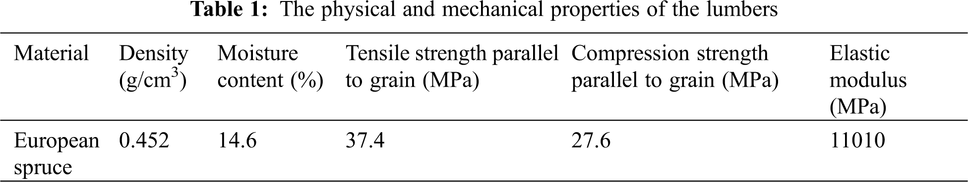
The 3-ply cross laminated timber (CLT) panels were made from European spruce lumbers. The experimental mean value of physical and mechanical properties for the full sized lumbers are shown in Tab. 1. The dimensions of the CLT elements are 1440 mm (length) × 380 mm (width) × 105 mm (thickness) with a layer thickness of 35 mm.
The characteristic yield strength fy of the threaded rods is 800 MPa, which is provided by the manufacturer. The outer and root thread diameter of the rods are 20 mm and 15 mm, respectively. And the embedment length of the rods are 200 mm, 300 mm, 400 mm, and 500 mm, respectively. The threaded rods were embedded into the predrilled hole of CLT specimens by using a torque wrench. To match the torque wrench and nut, the screwed-in part at the extended end of the rods was processed into square head and followed bolted thread part, as shown in Fig. 1.
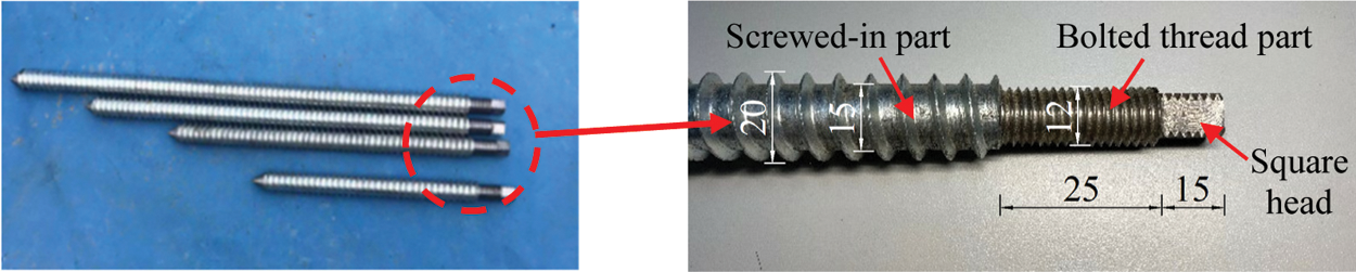
Figure 1: Geometry of the threaded rods
Self-tapping screws named of VGZ7100 (with the diameter of 7 mm and length of 100 mm) were used as the reinforcement perpendicular to the timber grain around the screwed-in threaded rods to avoid premature splitting failure of the timber in some specimens. The characteristic yield strength fy of the screws is 1000 MPa, which is provided by the manufacturer.
The test series were divided into ten subgroups of three specimens each, as shown in Tab. 2. The primary test parameters include the embedment length, the rod number and with or without the reinforcements.
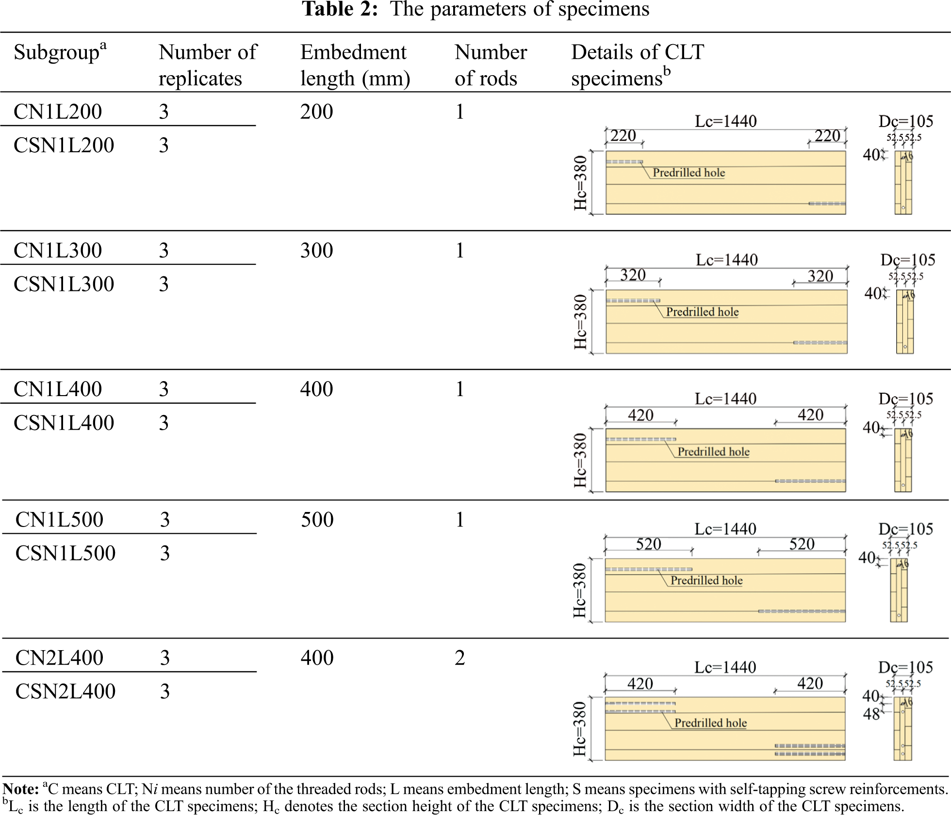
To reduce potential risk of timber splitting failure, the self-taping screws with the spacing of 50 mm were screwed in perpendicular to the grain of the CLT specimens CSN1L200, CSN1L300, CSN1L400, CSN1L500 and CSN2L400, and the configuration of the reinforcing screws are shown in Fig. 2. The spacing and the end distance were designed as 50 mm and 25 mm, respectively.
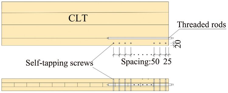
Figure 2: The layout of self-tapping screws in CLT specimens
2.4 Equipment and Experimental Procedure
In order to sufficiently simulate the use of threaded rods in CLT shear wall, a special loading device was designed to transfer the pull-out load against the horizontal load, as shown in Fig. 3. The specimen was anchored on the device with the threaded rod by using the bolted thread part. Also, steel plates were connected on both side of the specimens by bolts.
The withdrawal load applied on the threaded rods(F) can be calculated by the mechanical equilibrium condition, as shown in Eq. (1).
where, Fa is the load obtained from the actuator; l0 is the distance from the load center to the rotation center, as shown in Fig. 4, which is 1326 mm in this study; da is the distance from the rods center to the rotation center, as shown in Fig. 4, which is 221 mm in this work.
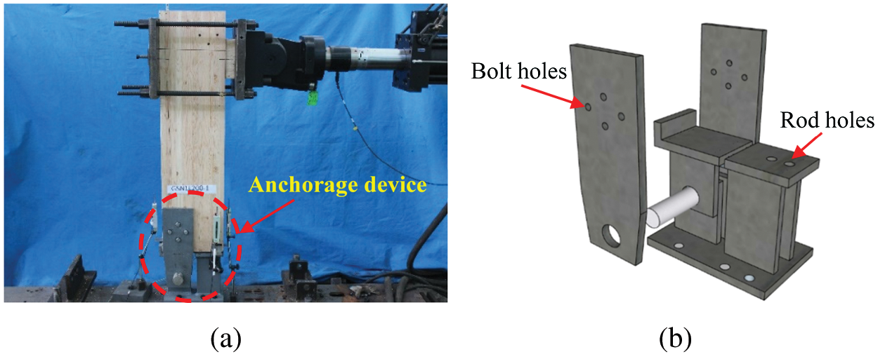
Figure 3: Test set-up (a) Full view of the test set-up (b) Schematic diagram of the anchorage device
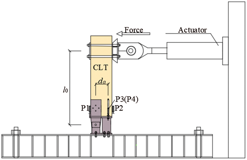
Figure 4: Loading and measuring device
The loading and measuring devices are illustrated in Fig. 4. Two Linear Variable Displacement Transformers (LVDTs) named “P1” and “P2” were installed at the side of the specimens to measure the relative angle, while the LVDTs “P3” and “P4” were set to measure the relative slip between the threaded rods and the timber elements. The loading rate of the horizontal actuator was set as 12 mm/min during the test, equaling to the withdrawal load of approximately 2 mm/min on the threaded rods, according to ASTM D1761 [28].
Then the average interfacial shear stress (τ) can be determined as follows:
where, Fmax is the maximum load born on the threaded rods, which can be calculated by Eq. (1); db is the diameter of self-tapping tapping bar, and la is the embedment length.
At the early loading stage, no visible slip occurred between CLT elements and the screwed-in threaded rods. With the increase of the applied load, the slip developed generally and then became notable. Finally, the following three typical failure modes was obtained, as shown in Fig. 5.
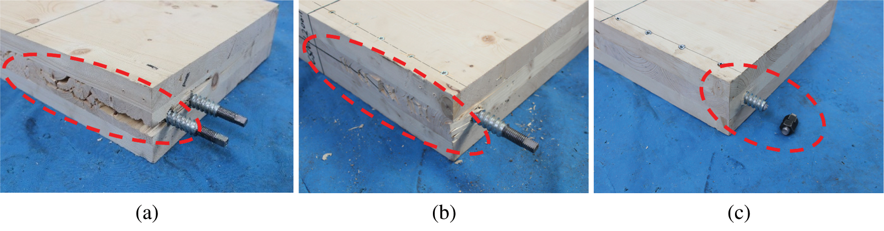
Figure 5: Typical failure modes of the specimens (a) Mode 1 (b) Mode 2 (c) Mode 3
Mode 1: Splitting of timber (see Fig. 5a). This failure mode occurred in most of the specimens without the self-tapping screw reinforcement, in which includes the subgroups CN1L200, CN1L300, CN1L400, CN1L500, and CN2L400. This is due to the high stress level perpendicular to the timber grain as a result of the relatively large deformation in the later loading stage.
Mode 2: Rolling shear failure of timber (see Fig. 5b). It occurred on the specimens with short embedment length and with self-tapping screw reinforcement (e.g., subgroups CSN1L200 and CSN1L300). Although the rolling shear appeared, the specimens can still bear a high load result from the restriction of the adjacent laminar and the reinforcement of the self-tapping screws. It demonstrates that the presence of self-tapping screws can prevent the splitting failure of timber to a considerable extent. However, due to the short embedment length, the threaded rods tend to pull-out from the CLT specimens, resulting in the rolling shear failure of the timber.
Mode 3: Yielding or fracture of the threaded rods (see Fig. 5c). This type of failure occurred in the specimens with the self-tapping screw reinforcement and the threaded rods with larger embedment length (e.g., subgroups CSN1L400, CSN1L500, and CSN2L400). Additionally, no obvious damage was found on the CLT elements. It indicates that with large embedment length of threaded rods and adequate reinforcement of self-tapping screws, the withdrawal capacity of the rod and the shearing capacity of the timber at the edge region were all highly strengthened. Thereby, the weak point transferred to the threaded rods, exhibiting the yield or even fracture behaviour of the rods at the peak load.
The pull-out load-slip curves of the test specimens are shown in Fig. 6, which can be divided into four stages, including the non-slip stage, linear elastic stage, non-linear stage and descent stage. Also it can be seen from the figure that most of the specimens present obvious ductile behaviour. For the specimens with large embedment length of threaded rods and adequate reinforcement of self-tapping screws, although the curves drop sharply when reach to the peak load, the failure can also be seen as ductile ones due to its considerable slip.
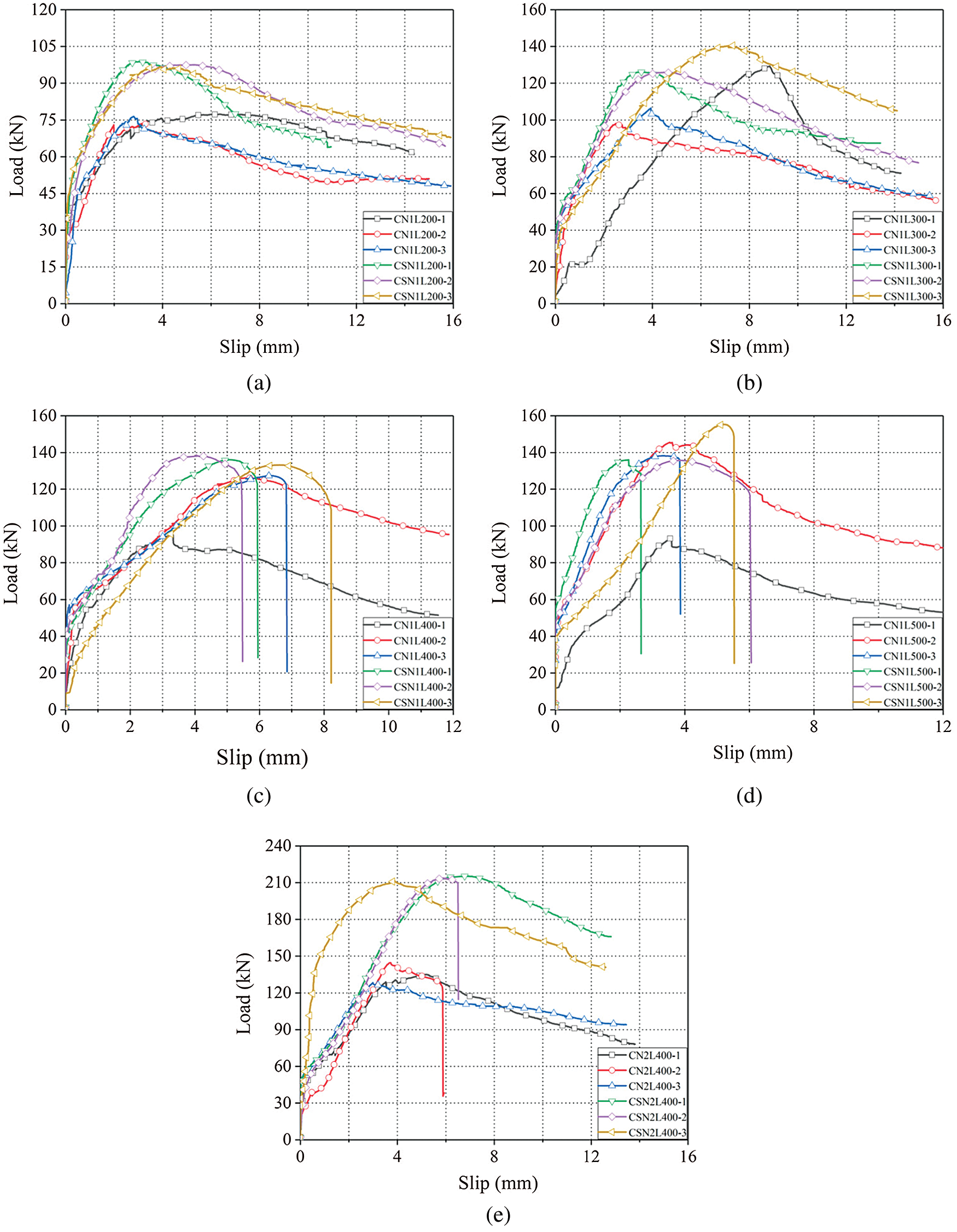
Figure 6: Load-Slip curves of the specimens (a) CN1L200 and CSN1L200 (b) CN1L300 and CSN1L300 (c) CN1L400 and CSN1L400 (d) CN1L500 and CSN1L500 (e) CN2L400 and CSN2L400
Based on the test results, the withdrawal capacity and average interfacial shear stress(τ) can be calculated according to Eqs. (1) and (2), respectively. Additionally, as illustrated in Fig. 6, there are four stages for the load-slip curves, in which no obvious slip occurs at the first one. Consequently, the slip stiffness presented herein can be derived from the linear elastic stage of the load-slip curves, as shown in Fig. 7 and Eq. (3).
where, F0 is the load at the occurring of slip; s0.4 is the slip at the load level of F0.4.
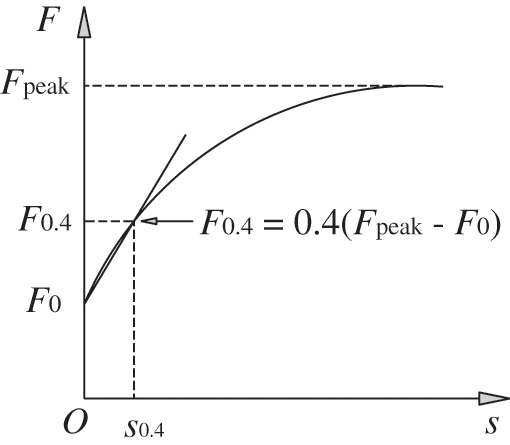
Figure 7: Characteristic points of load-slip curves
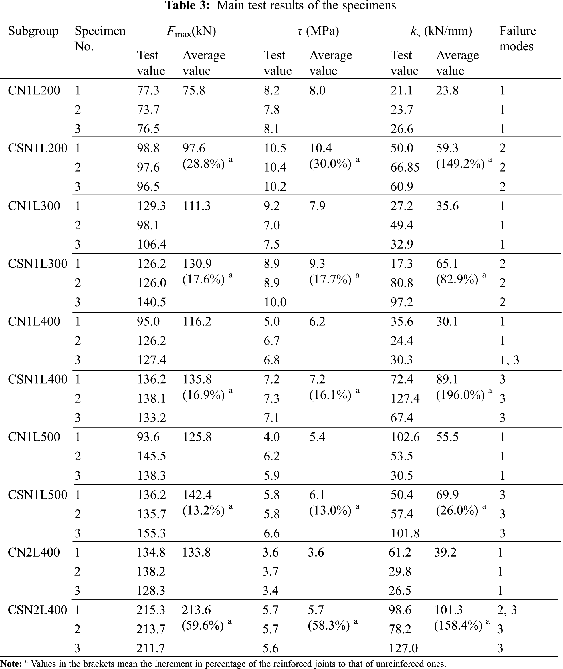
The main test results regarding to the withdrawal resistance(Fmax), average interfacial shear stress(τ) and slip stiffness(ks) of the specimens calculated according to Eqs. (1)–(3) are listed in Tab. 3.
Based on the test results listed in Tab. 3, the comparisons on the withdrawal capacity of the specimens are shown in Fig. 8. It can be seen from Fig. 8a that the pull-out capacity increases considerably as the embedment length increased from 200 mm to 300 mm, in which increases by 34.1% for reinforced specimens and 46.8% for unreinforced ones. Subsequently, there was a slight improvement when the embedment length exceeds 300 mm. It is reasonable since the failure of the pull-out specimens turns from timber shear failure into rod yielding or fracture failure. In addition, it was found that the withdrawal capacity of the specimens with reinforcements was higher than those without reinforcements. It was proved that the self-tapping screws can reduce the splitting failure of timber, and consequently improve the pull-out resistance of the specimens.
As illustrated in Fig. 8b, when the number of rods increases from 1 to 2, the average pull-out capacity increases by 57.3% for the specimens with reinforcement, while increases only 15.1% for the unreinforced specimens. It shows that the pull-out capacity of screwed-in threaded rods in CLT elements is sensitive to the rod number, especially for the reinforced specimens. It is considered that, for the specimens without self-tapping screws, the withdrawal capacity mainly depends on the splitting resistance of timber. Therefore, increasing the number of rods in this situation have limited benefit on the withdrawal capacity. However, when enhanced by the self-tapping screws, the withdrawal resistance is mainly determined by the strength of the threaded rods. As a result, increasing the number of rods of reinforced specimens could significantly increase the withdrawal capacity.
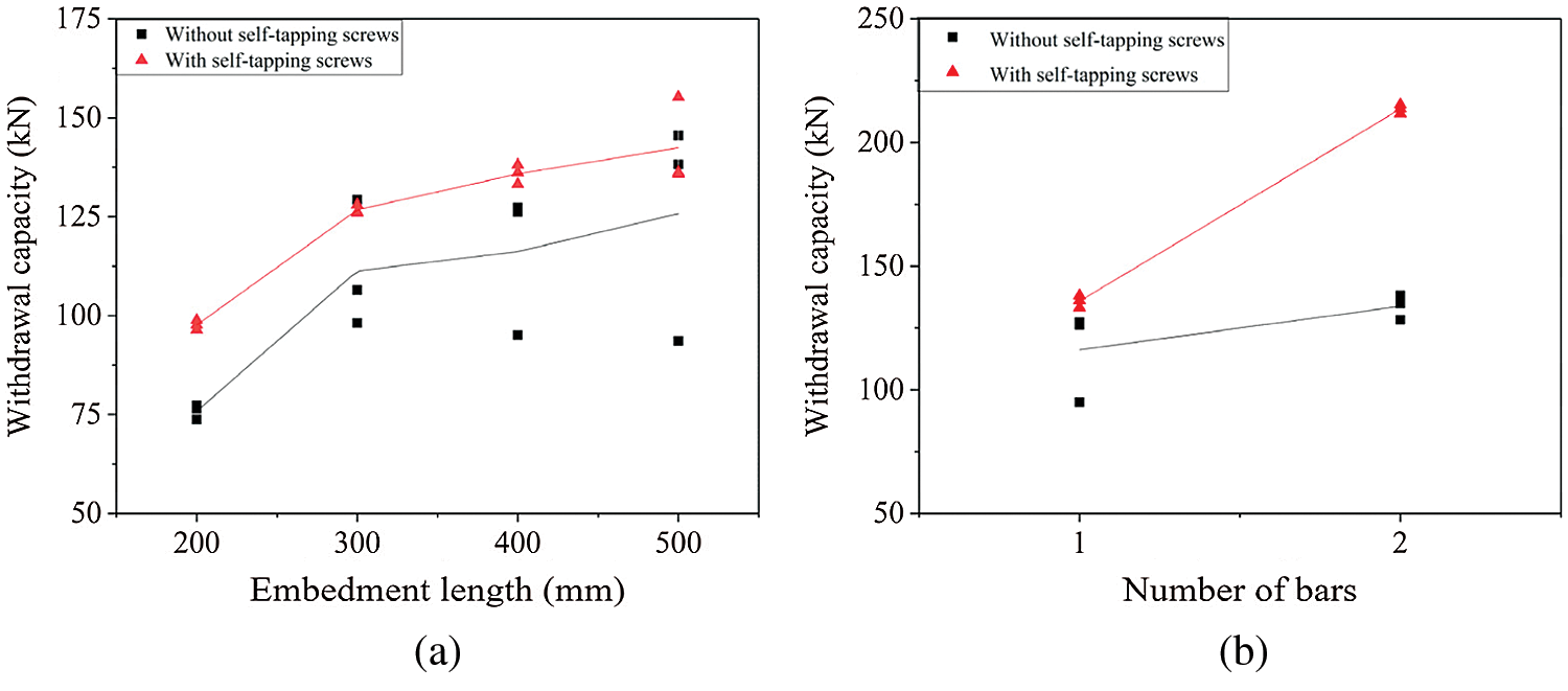
Figure 8: Comparison on the withdrawal capacity (a) Effect of embedment length (b) Effect of number of rods
The comparisons in regard of the average interfacial shear stress (calculated according to Eq. [2]) between the specimens are plotted in Fig. 9.
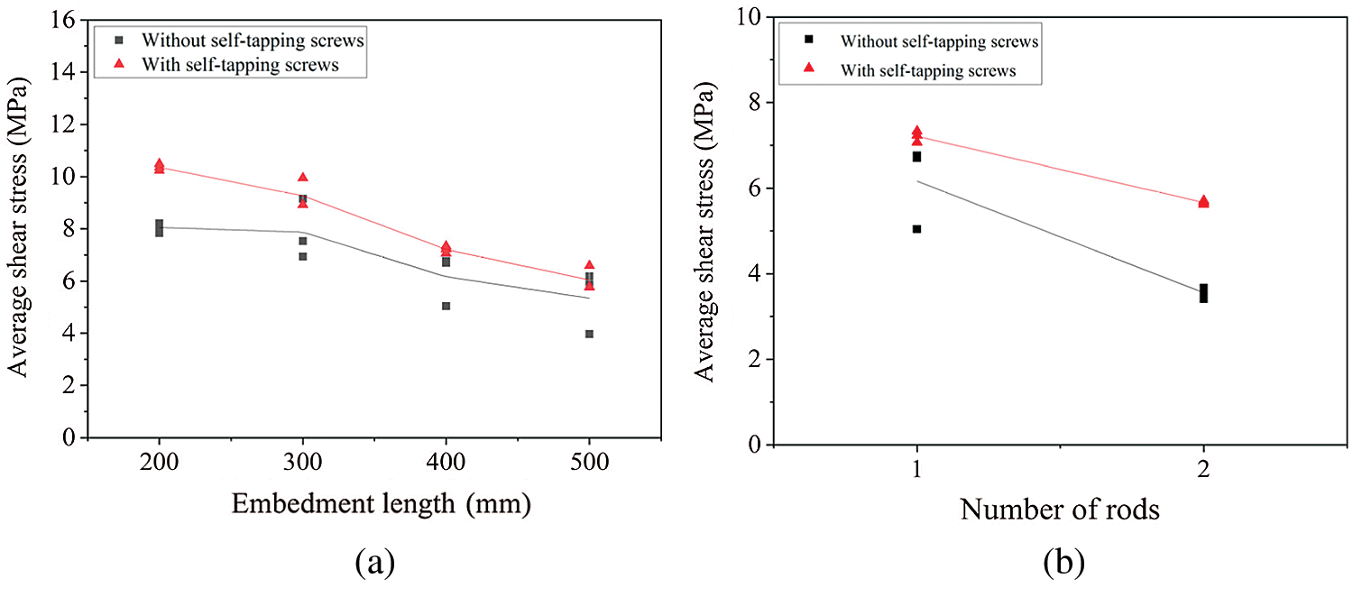
Figure 9: Comparison on average interfacial shear stress (a) Effect of embedment length (b) Effect of number of rods
According to Fig. 9, it could be found that the average interfacial shear stress decrease as the embedment length or the rod number increase. Also, the average interfacial shear stress of the reinforced specimens are higher than that of the specimens without the self-tapping screws. Similar with that mentioned before, the reason is that the self-tapping screws can reduce the splitting behaviour of the timber and make more use of the tension resistance of the threaded rods, consequently improving the ultimate withdrawal resistance and average interfacial shear stress of the specimens.
The comparisons in regard of the slip stiffness (calculated according to Eq (3)) between the specimens are shown in Fig. 10. It can be seen that before the rods reached the yielding or fracture length level, there is a linear relationship between the slip stiffness and the embedment length. Also the number of rods has an obvious effect on the slip stiffness. It should be noted that the self-tapping screw reinforcement present a remarkable improvement on the slip stiffness. The improvement can reach 196%. Moreover, it seems that the improvement will be higher while the number of rods become bigger.
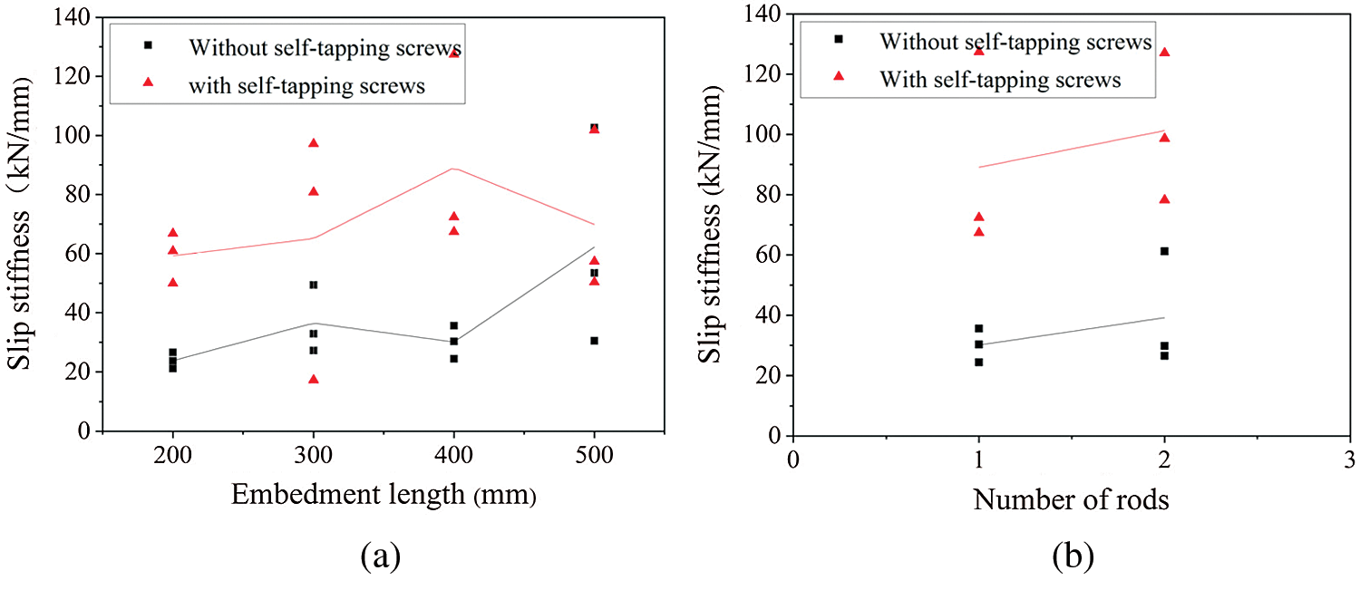
Figure 10: Comparison on slip stiffness (a) Effect of embedment length (b) Effect of number of rods
The pull-out behaviour of axially loaded screwed-in threaded rods embedded in CLT elements, with and without self-tapping screw reinforcements, was studied by experimental study. The effects of embedment length and number of threaded rods on the withdrawal capacity and slip stiffness were also evaluated. The following main conclusions are drawn:
• The evaluated specimens in this work showed good pull-out behaviour in the respect of withdrawal capacity, slip stiffness and interfacial shear stress, etc.
• The main failure modes of the test specimens include: 1) splitting of timber, 2) rolling shear failure of timber, and 3) yielding or even fracture of the threaded rods.
• The pull-out capacity increases considerably when the embedment length increased from 200 mm to 300 mm, while it rises slowly when the embedment length exceeds 300 mm.
• The average interfacial shear stress will decrease as the embedment length or the rod number increases.
• The self-tapping screws played an important role in reducing or even preventing the splitting failure of the timber, which can improve the ultimate pull-out resistance, average interfacial shear stress and slip stiffness of the specimens.
• When increasing the number of the threaded rods, the improvement in regard of the withdrawal capacity and stiffness of the specimens with self-tapping screw reinforcements are much more obvious than that of the specimens without the self-tapping screws, owing to the change of failure modes.
Funding Statement: This research was sponsored by the National Natural Science Foundation of China (Grant Nos. 51878344 and 51578284).
Conflicts of Interest: The authors declare that they have no conflicts of interest to report regarding the present study.
1. Dorn, M., de Borst, K.,Eberhardsteiner, J. (2013). Experiments on dowel-type timber connections. Engineering Structures, 47(2), 67–80. DOI 10.1016/j.engstruct.2012.09.010. [Google Scholar] [CrossRef]
2. Liu, W. Q., Yang, H. F. (2019). Research progress on modern timber structures. Journal of Building Structures, 40(2), 16–43. DOI 10.14006/j.jzjgxb.2019.02.002 (in Chinese). [Google Scholar] [CrossRef]
3. Stamatopoulos, H. (2016). Withdrawal properties of threaded rods embedded in glued-laminated timber elements, (Ph.D. Thesis). NTNU, Norwegian University of Science and Technology, Norway. [Google Scholar]
4. Stamatopoulos, H., Malo, K. A. (2015). Withdrawal capacity of threaded rods embedded in timber elements. Construction and Building Materials, 94, 387–397. DOI 10.1016/j.conbuildmat.2015.07.067. [Google Scholar] [CrossRef]
5. Stamatopoulos, H., Malo, K. A. (2016). Withdrawal stiffness of threaded rods embedded in timber elements. Construction and Building Materials, 116, 263–272. DOI 10.1016/j.conbuildmat.2016.04.144. [Google Scholar] [CrossRef]
6. Blass, H. J., Laskewitz, B. (1999). Effect of spacing and edge distance on the axial strength of glued-in rods. Proceedings CIB-W18A. Graz, Austria. [Google Scholar]
7. Broughton, J. G., Hutchinson, A. R. (2001). Pull-out behaviour of steel rods bonded into timber. Materials and Structures, 34(2), 100–109. DOI 10.1007/BF02481558. [Google Scholar] [CrossRef]
8. Yeboah, D., Taylor, S., McPolin, D., Gilfillan, R., Gilbert, S. (2011). Behaviour of joints with bonded-in steel bars loaded parallel to the grain of timber elements. Construction and Building Materials, 25(5), 2312–2317. DOI 10.1016/j.conbuildmat.2010.11.026. [Google Scholar] [CrossRef]
9. Steiger, R., Gehri, E., Widmann, R. (2007). Pull-out strength of axially loaded steel rods bonded in glulam parallel to the grain. Materials and Structures, 40(1), 69–78. DOI 10.1617/s11527-006-9111-2. [Google Scholar] [CrossRef]
10. Tlustochowicz, G., Serrano, E., Steiger, R. (2011). State-of-the-art review on timber connections with glued-in steel rods. Materials and Structures, 44(5), 997–1020. DOI 10.1617/s11527-010-9682-9. [Google Scholar] [CrossRef]
11. Fragiacomo, M., Batchelar, M. (2011). Timber frame moment joints with glued-in steel rods. I: design. Journal of Structural Engineering, 138(6), 789–801. DOI 10.1061/(ASCE)ST.1943-541X.0000419. [Google Scholar] [CrossRef]
12. Ling, Z., Yang, H., Liu, W., Lu, W., Zhou, D. et al. (2014). Pull-out strength and bond behaviour of axially loaded rebar glued-in glulam. Construction and Building Materials, 65(2), 440–449. DOI 10.1016/j.conbuildmat.2014.05.008. [Google Scholar] [CrossRef]
13. Yang, H. F., Liu, W. Q., Ren, X. (2016). A component method for moment-resistant glulam beam-column connections with glued-in steel rods. Engineering Structures, 115(11), 42–54. DOI 10.1016/j.engstruct.2016.02.024. [Google Scholar] [CrossRef]
14. Gaunt, D. (1997). The effect of thread geometry on screw withdrawal strength. NZ Timber Design Journal, 6, 12–20. [Google Scholar]
15. Ellingsbø, P., Malo, K. A. (2012). Withdrawal capacity of long self-tapping screws parallel to grain direction, Proceedings of the 12th World Conference on Timber Engineering. Auckland, New Zealand. [Google Scholar]
16. Ringhofer, A., Brandner, R., Schickhofer, G. (2015). Withdrawal resistance of self-tapping screws in unidirectional and orthogonal layered timber products. Materials and Structures, 48(5), 1435–1447. DOI 10.1617/s11527-013-0244-9. [Google Scholar] [CrossRef]
17. Ringhofer, A., Grabner, M., Silva, C., Branco, M., Schickhofer, G. (2014). The influence of moisture content variation on the withdrawal capacity of self-tapping screws. Holztechnologie, 55, 33–40. [Google Scholar]
18. Frese, M., Blaß, H. J. (2009). Models for the calculation of the withdrawal capacity of self-tapping screws. Proceedings of the 42nd CIB-W18 Meeting, Dübendorf, Switzerland. [Google Scholar]
19. Jensen, J. L., Nakatani, M., Quenneville, P., Walford, B. (2011). A simple unified model for withdrawal of lag screws and glued-in rods. European Journal of Wood and Wood Products, 69(4), 537–544. DOI 10.1007/s00107-010-0478-y. [Google Scholar] [CrossRef]
20. Jensen, J. L., Nakatani, M., Quenneville, P., Walford, B. (2012). A simplified model for withdrawal of screws from end-grain of timber. Construction and Building Materials, 29(3), 557–563. DOI 10.1016/j.conbuildmat.2011.10.066. [Google Scholar] [CrossRef]
21. Nakatani, M., Mori, T., Komatsu, K. (2006). Development of moment-resisting joint systems using lagscrewbolts. Proceedings of the 9th World Conference on Timber Engineering. Portland, USA. [Google Scholar]
22. Stamatopoulos, H., Malo, K. A. (2018). Withdrawal of pairs of threaded rods with small edge distances and spacings. European Journal of Wood and Wood Products, 76(1), 31–42. DOI 10.1007/s00107-016-1146-7. [Google Scholar] [CrossRef]
23. Stamatopoulos, H., Malo, K. A. (2020). On strength and stiffness of screwed-in threaded rods embedded in softwood. Construction and Building Materials, 261(5), 119999. DOI 10.1016/j.conbuildmat.2020.119999. [Google Scholar] [CrossRef]
24. Mori, T., Nakatani, M., Tesfamariam, S. (2015). Performance of semirigid timber frame with Lagscrewbolt connections: experimental, analytical, and numerical model results. International Journal of Advanced Structural Engineering, 7(4), 387–403. DOI 10.1007/s40091-015-0107-4. [Google Scholar] [CrossRef]
25. Komatsu, K., Morimoto, T., Kurumada, S., Tanaka, H., Shimizu, T. et al. (2018). Development of glulam moment-resisting joint having high initial stiffness, clear yielding moment and rich ductility. Proceedings of the 15th World Conference on Timber Engineering. Seoul, Korea. [Google Scholar]
26. Mori, T., Nakatani, M., Chui, Y., Gong, M., Isoda, H. et al. (2014). Pull-out strength properties of lagscrewbolt connection in cross laminated timber. Proceedings of the 13th World Conference on Timber Engineering. Quebec, Canada. [Google Scholar]
27. Nakatani, M., Mori, T., Suzuki, K. (2018). Effect of embedded condition of lagscrewbolt in cross laminated timber on the pull-out properties. Proceedings of the 15th World Conference on Timber Engineering. Seoul, Korea. [Google Scholar]
28. ASTM D1761-20 (2020). Standard test methods for mechanical fasteners in wood. USA: ASTM International. [Google Scholar]
 | This work is licensed under a Creative Commons Attribution 4.0 International License, which permits unrestricted use, distribution, and reproduction in any medium, provided the original work is properly cited. |