| Journal of Renewable Materials |
DOI: 10.32604/jrm.2021.015925
ARTICLE
Numerical Investigation of Connection Performance of Timber-Concrete Composite Slabs with Inclined Self-Tapping Screws under High Temperature
1Department of Civil Engineering, Nanjing Tech University, Nanjing, 211816, China
2Architectural Design and Research Institute of Nanjing Tech University, Nanjing, 210009, China
*Corresponding Author: Weidong Lu. Email: wdlu@njtech.edu.cn
Received: 24 January 2021; Accepted: 24 March 2021
Abstract: The timber-concrete composite (TCC) slabs have become a preferred choice of floor systems in modern multi story timber buildings. This TCC slab consisted of timber and a concrete slab which were commonly connected together with inclined self-tapping screws (STSs). To more accurately predict the fire performance of TCC slabs, the mechanical behavior of TCC connections under high temperature was investigated by numerical simulation in this study. The interface slip of TCC connections was simulated by a proposed Finite Element (FE) model at room temperature, and different diameter and penetration length screws were considered. The effectiveness of this FE model was validated by comparing with the existing experimental results. Furthermore, the sequentially coupling thermal stress analyses of this model were conducted, and the relationship between the reduction coefficient of connection performance and the effective penetration length of screws was summarized. This study gave the fitting expressions for the reduction coefficient of slip modulus and joint strength. Finally, the numerical investigations of the fire performance of TCC slabs considering the char fall-off of Cross Laminated Timber (CLT) were performed to verify the effectiveness of the proposed reduction law. Comparing the fire-resistance time with experimental results showed deviation of the proposed model was −14.02%.
Keywords: Cross laminated timber; finite element; fire resistance; shear connection; timber-concrete composite
With developing different production processes, Laminated Veneer Lumber (LVL), Glued Laminated Timber (GLT), Parallel Strand Lumber (PSL), Oriented Strand Lumber (OSL), Cross Laminated Timber (CLT) were widely used in engineered wood production. In which CLT with high stiffness and strength in both in-plane directions can compensate for the defect of wood anisotropy [1] and is suitable to be used in floor systems [2]. The CLT and concrete slab are commonly connected together by shear connections to develop the timber-concrete composite (TCC) slab. This TCC slab as one of the most environmental friendly floor systems is widely used in modern multi story timber buildings, which takes the following advantages: high bearing capacity and rigidity [3], improved vibration and acoustic performance [4,5], reduced floor depth [6], excellent fire resistance [7,8] and so on.
Self-tapping screw (STS) is one of the most common connectors of TCC slab because of combining the advantages of high connection performance, simple production process and quick assembly. There has been much research on the connection properties of STSs for this composite slab. However, most of these studies [9] were conducted under ambient temperature condition. The failure mechanism and mode of inclined cross lag screws for TCC beams has been demonstrated and critically discussed [10]. With varying screw diameters, embedded depth, inclination angle and arrangement, push-out tests of TCC beams were conducted to assess the shear behavior of STSs in term of both the strength and stiffness [11,12]. In the theoretical analysis, various calculation models of screw shear behavior under ambient temperature have been proposed [11,13] and good agreement was found between calculation and experimental results. As for finite element analysis, many researchers have developed various reliable FE models of push-out test [14–17], which could accurately predict the connection behavior of screw between wood and wood at ambient temperature. The two FE models respectively proposed by Dias et al. [18] and Oudjene et al. [19] could provide accurate predictions when comparing connection performance of TCC beams with the experimental results.
Nowadays, many studies related to the fire resistance of STS have been conducted in the past few decades. The FE model proposed by Bedon et al. [20] predicted the fire behavior of axially loaded screws precisely. Palma et al. [21] carried out an experimental study on the fire resistance of steel-to-timber dowelled connections, which showed the cross section of wood members had a significant impact. Frangi et al. [22] carried out a research on the fire resistance performance of TCC beam-type slabs with screwed connectors. Authors found that the reduction of connection performance in fire is mainly governed by the thickness of wood on the screw side instead of on the screw bottom. As CLT can provide adequate thickness of wood on the screw side, CLT can be regarded as the fireproof layer of screws. However, Auclair et al. [23] and Dagenais et al. [24] built a numerical model to predict the fire resistance of TCC. The results showed that the connection performance of screws under high temperature has a great influence on the bearing capacity of TCC slab. This FE model adapted the connection strength by multiplying the JPL factor [25] related to the lag screw penetration length. But there is no study to discover the effect of the reduction of screw connection property under high temperature on the structural performance of this composite slab [24].
In this paper, a FE model of shear behavior of TCC connections with different diameter and penetration length screws at room temperature was proposed. The proposed model was validated by the experimental data. Furthermore, this numerical model was used to provide the reduction law of connection performance under high temperatures. The coupled thermo-mechanical model considering the reduction law was developed. This model can predict the fire resistance of TCC slabs in a fire precisely.
2 Simulation of the Shear Behavior of Inclined STSs at Ambient Temperature
The finite element software ABAQUS was used to conduct the numerical simulation. The FE model of TCC connection was composed of the two concrete members and a timber member connected by inclined self-tapping screws with an angle of 45°, as shown in Fig. 1. Different screw diameters and penetration lengths summarized in Tab. 1 were employed in the simulation analysis. And only a quarter of the model was adopted because of the symmetry of the test specimen [11,12].
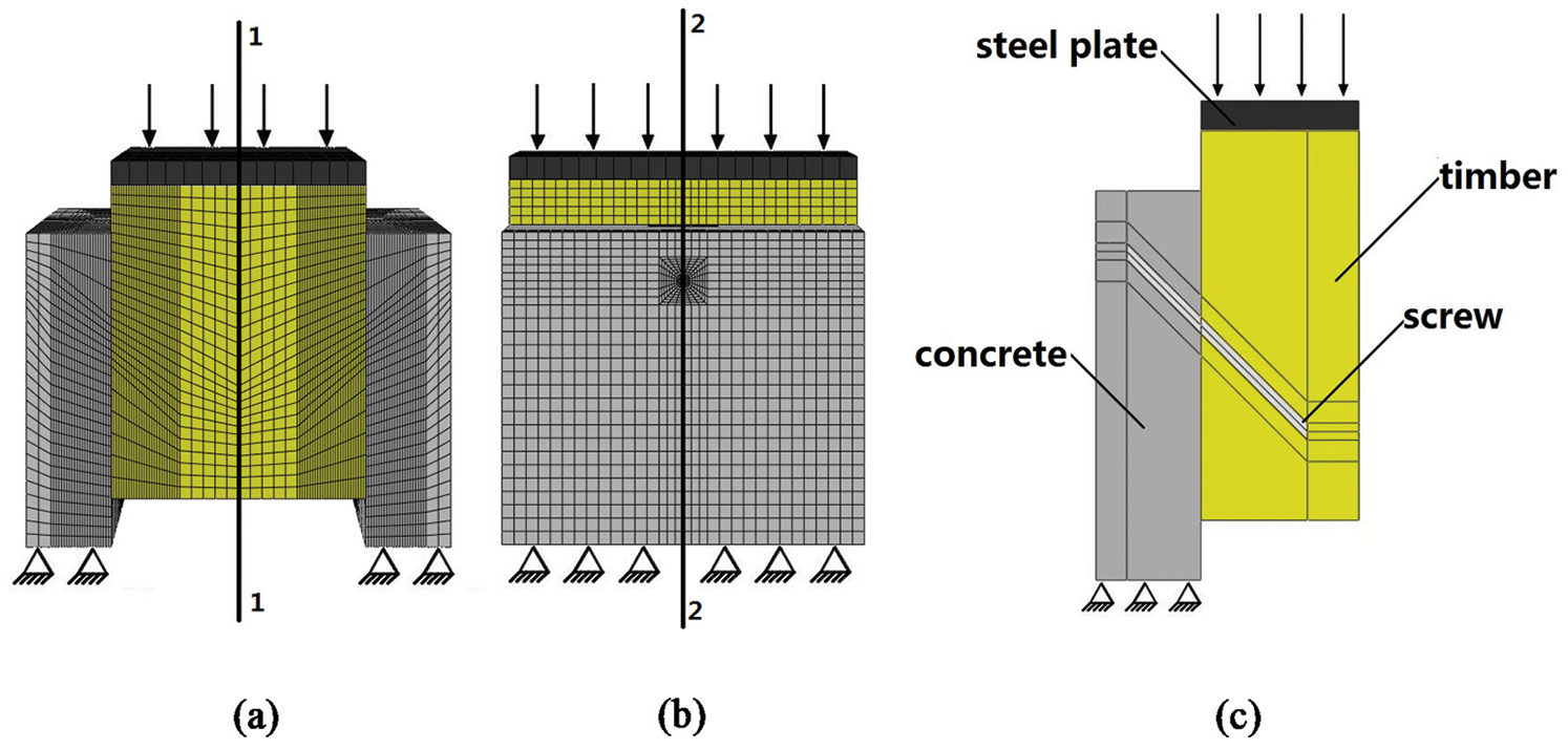
Figure 1: FE model of push-out TCC beams joints with inclined STSs. (a) Symmetry plane 1–1, (b) symmetry plane 2–2 and (c) a quarter of the model
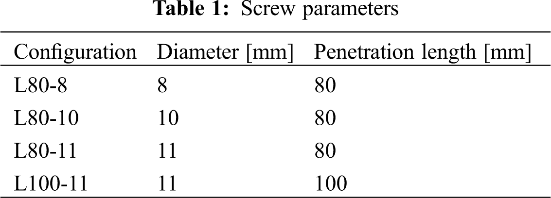
According to the isotropic, elastic-plastic constitutive law of steel [26,27], the constitutive behavior of screw was modeled, as shown in Fig. 2a. Therefore, the elastic modulus and Poisson’ ratio of steel screw were taken as 210 GPa and 0.3, respectively. The yielding and ultimate stress values were fy = 330 MPa and fu = 450 MPa, respectively. Similarly, concrete was regarded as an isotropic elasto-plastic material, and its constitutive law was presented in Fig. 2b. The constitutive behavior of concrete was modeled by elastic and softening behavior for tension, and elastic, hardening and softening behavior for compressive. And the concrete damage behavior was modeled by the concrete damage plasticity (CDP) theory. The elasticity modulus (Ec), the compressive strength (fc’) and Poisson’s ratio coefficient (ν) of concrete [11,12] were presented in Tab. 2. The yield surfaces of steel and concrete were both defined by von Mises yield criterion.
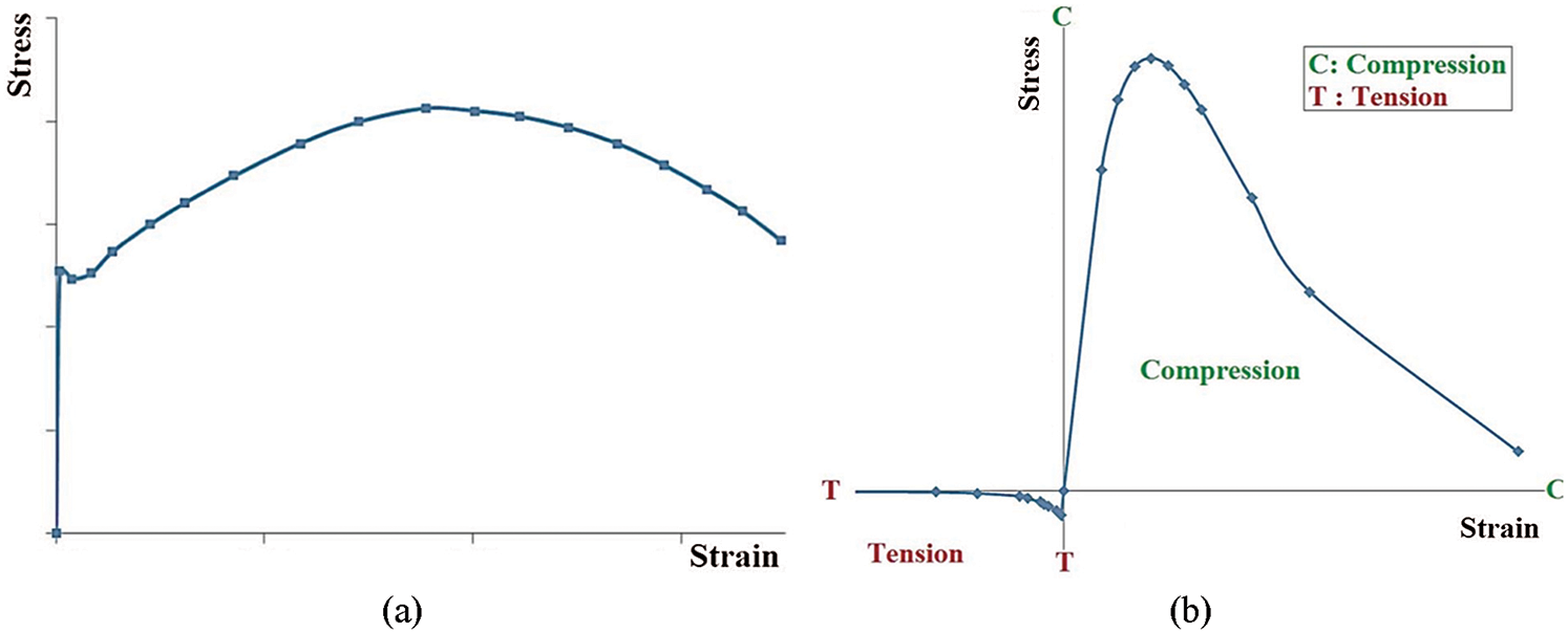
Figure 2: Stress-strain relationships for (a) steel and (b) concrete [27]

Due to the anisotropy of wood, an orthotropic elastic-plastic model based on the Hill criterion was adopted. The elastic modulus, the shear modulus and the Poisson’ ratio in the various directions were given in Tab. 3. The compressive strength value parallel to the grain was determined as fc,L = 43 MPa. The remaining Hill stress ratio were calculated along radial (R) and tangential (T) directions, so as to set the compressive strength value perpendicular to the grain to fc,R = fc,T = 5.16 MPa. The shear strength value was set to fv = 5.16 MPa.

2.2 Boundary Conditions and Contacting Law
As a quarter of the model was built, the symmetric boundary conditions were needed for symmetry plane 1–1 and 2–2 (as shown in Fig. 1). The supports were at the bottom of the concrete. They were simulated by setting the three translations of all the nodes that correspond to support areas to values of zero displacements. The push-out tests controlled by displacements were applied on all the nodes at the top of the timber.
About contact, two types of contact properties need to be defined to simulate the contact between the wood and concrete, wood and screws, and concrete and screws. The surface-to-surface ‘hard’ method was adopted to simulate the normal contact, while the surface-to-surface ‘penalty’ method was used to simulate tangential contact. The static friction coefficient between timber and concrete was set as μ = 0.65 [13]. Since no slip between the concrete and screw was observed during the push-out tests, the static friction coefficient between them was assumed to be 0.9 [18].
To consider the possible brittle failure at the screw-to-timber interface and the pretension around the self-tapping screws, a simplified numerical model was proposed to simulate the withdrawal behavior of STSs, which combines the friction and cohesive contact. The surfaces between the screw and timber around the screw were interrelated by a tangential ‘penalty’/normal ‘hard’ interaction. And the contact between the screw and timber under the screw was set to a ‘cohesive contact’ interaction (see Fig. 3). The friction coefficients between the screw and timber around the screw are summarized in Tab. 4. The cohesive surface behavior was defined as the linear elastic traction-separation. The elastic modulus is summarized in Tab. 4. In this paper, the maximum nominal stress (MAXS) criterion [15] was adopted as the ‘damage initiation criterion’ for the cohesive surface so that:
Figure 3: The contact behavior of the surfaces between the timber and screw
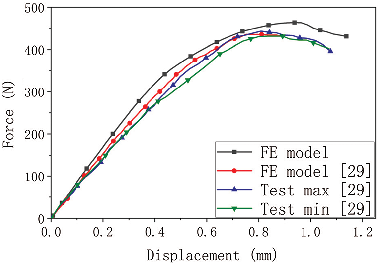
Figure 4: The force-displacement curves obtained from [29] and this paper

2.3 Validation of the Numerical Model
Fig. 5 shows the comparison of the load-slip curves of tests obtained from [11,12] and numerical simulations. The ultimate load, slip stiffness and post-failure behavior obtained in the tests were reasonably simulated by this numerical model. The trend of the load slip curves obtained from the FE model was consistent with test results, especially in the initial and degradation stage. But the load of the Specimen L80-8 is underestimated when the value of slip is between 0.71 and 2.34. It should be pointed that the fell segment of experimental curve is much steeper in the load slip curves of the specimen L100-11. The reason is that the brittle failure models such as concrete cracking and wood cracking are not simulated by this FE model. Besides, it was found the numerical results of the specimens L80-10 and L80-11 were overestimated. According to EN 26891 [31], the slip modulus Ks can be expressed as:
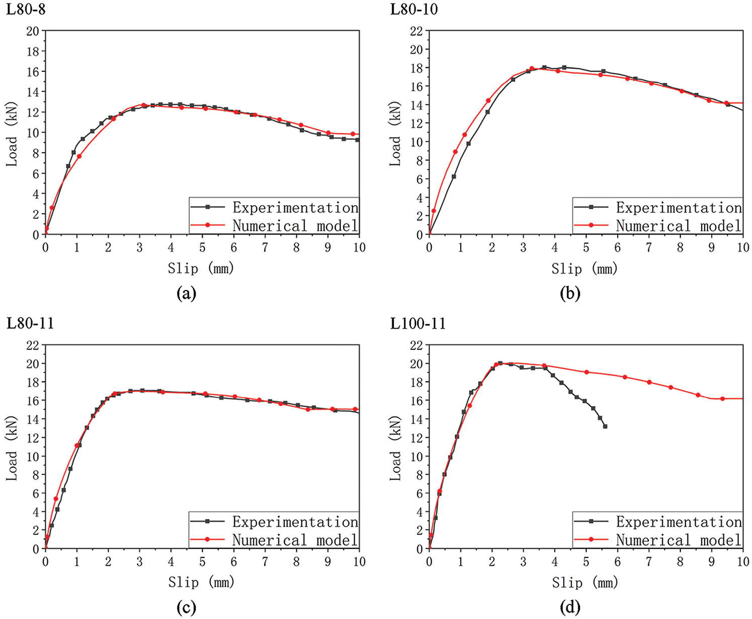
Figure 5: Experimental and numerical load-slip curves. The specimens are (a) L80-8, (b) L80-10, (c) L80-11, (d) L100-11, respectively

3 The Reduction Law of STSs Connection Performance with Increasing Temperature
Aiming to find the reduction law of screw connection performance under the high temperature, the sequentially coupling thermal stress analyses were conducted based on Section 1. The screw diameter and penetration length of the numerical model are 8 and 100 mm derived from [7], respectively. Firstly, a thermal analysis was carried out to determine the temperature profile of the push-out specimens. Then, the temperature field was input into the structure of the model for a stress analysis.
In the thermal model, the involved thermophysical properties, including the density, thermal conductivity and specific heat, was set. According to EN1995-1-2 [32] and EN 1993-1-2 [33], the property parameters of wood and screw weakened with increasing temperature were set, respectively. The temperature of concrete was always at a low-level, hence the reduction of material properties with temperature was ignored. The thermophysical properties of concrete were determined in accordance with EN1994-1-2 [34]. The model was simulated by one-dimensional heat transfer throughout the cross section of the TCC components under standard fire curve CAN/ULC-S101 [35]:
When calculating the temperature field, all contact surfaces were defined as the ‘tie’ contact. The boundary conditions for surface heat thermal radiation and heat convection of the exposed surfaces need to be defined, during heat transfer. The emissivity and convection coefficients derived from Eurocode1 [36] were 25 W/m2K and 0.8, respectively.
Considering the change of mechanical properties with high temperature, the reduction of elasticity modulus and strength of wood and steel were obtained from the EN1995-1-2 [33] and EN 1993-1-2 [34]. As the temperature of concrete was always at a low-level, the reduction in mechanical properties with temperature was ignored according to EN 1994-1-2 [35].
In addition, the reduction of contact properties of the surfaces between wood and screws needs to be considered because of the charring of timber and softening of steel. The contact properties are related to the withdrawal behavior of the screw. The withdrawal strength was calculated using the following equation [13]:
where FN is the normal force, μ is the friction coefficient between the timber and fastener, and tn is the contact stress in the pure normal (n) mode. When the screw diameter is constant, the friction coefficient and contact strength have positive correlation to the effective penetration length.
The withdrawal stiffness was calculated using the following equation [13]:

Fig. 6 presents the load-slip curves of the numerical simulations at different burning times. The reduction of the joint strength Fmax and slip modulus KS with the burning time are shown in Fig. 7. Considering the different timber section and screw penetration length, this reduction relations were not always effective in modelling the behavior of STS under high temperature. The reduction of joint performance under elevated temperature is mainly related to the following factors: a. the reduction in mechanical properties of timber and steel with elevated temperature, b. The reduction of withdrawal behavior between wood and screw under high temperature. These negative factors are all related to the distribution of temperature field. The temperature field distribution of the screw and its surrounding timber is reflected by the effective penetration length. Thus, for determining the effective penetration length of screws, the calculation model shown in Fig. 8 was applied. The effective penetration length Lef is calculated as follows [22]:
where def is effective charring depth, dchar, ave is the average notional charring depth, dchar, 1 and dchar, 2 are the notional charring depth on both sides of the screw, k0 = 1.0, zero strength layer d0 = 7 mm, Ls is the initial penetration length of screw, t is the thickness of the timber under the screw. The graph of relation between the effective penetration length and reduction coefficient is shown in Fig. 9. Based on the above relationship, the fitting expressions (see Fig. 10) for the reduction coefficient of slip modulus and joint strength were given by Eqs. (10) and (11). The R2 value of slip modulus and joint strength are 0.99247 and 0.98966, respectively.
where RM and RS are the reduction coefficient of slip modulus and joint strength, respectively.
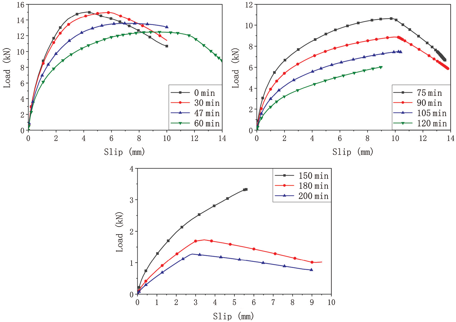
Figure 6: Numerical load-slip curves at different burning times
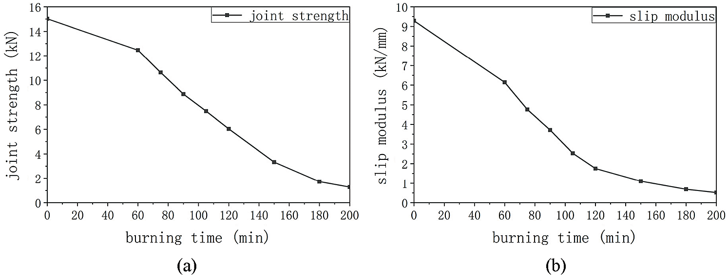
Figure 7: (a) The relation between the joint strength Fmax and the burning time, (b) the relation between the slip modulus KS and the burning time
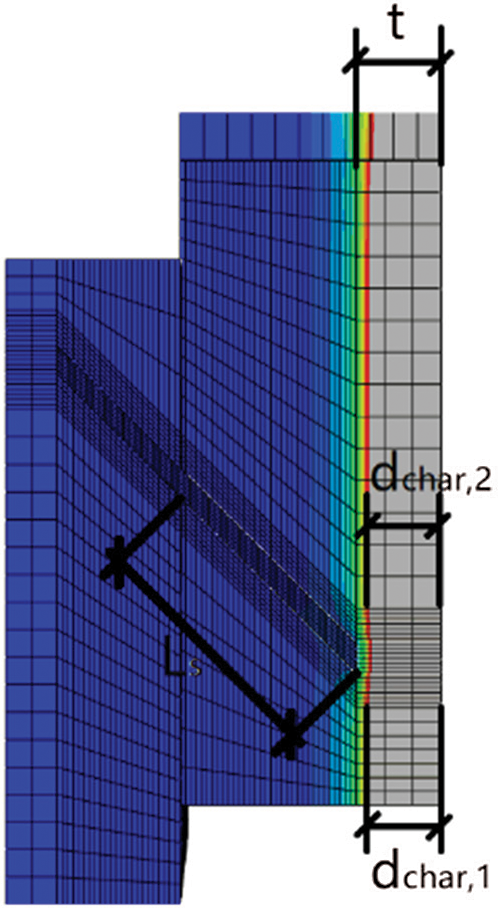
Figure 8: The calculation model for the effective penetration length of screws
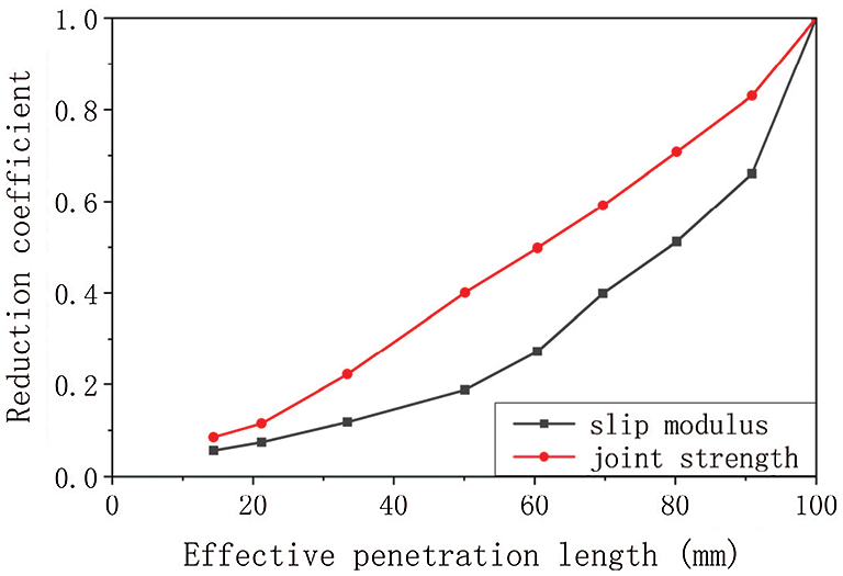
Figure 9: The relation between the effective penetration length and reduction coefficient
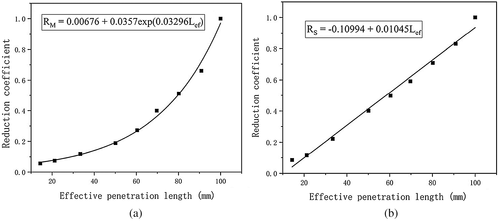
Figure 10: The fitting expressions for the reduction coefficient of (a) slip modulus and (b) joint strength
4.1 The Coupling Thermal Stress Model of TCC
Because of the symmetry of the test specimen [7], only a quarter of the model was built. According to the specimen of full-scale fire-resistant experiments, the thickness of the 5-ply CLT and concrete were simulated to be 175 and 89 mm, respectively (see Fig. 11). Since the specimen dimension was 1829 mm × 4800 mm, the size of the numerical model was set to 914.5 mm × 2400 mm. The sequentially coupling thermal stress analysis was adopted to simulate the fire resistance test.
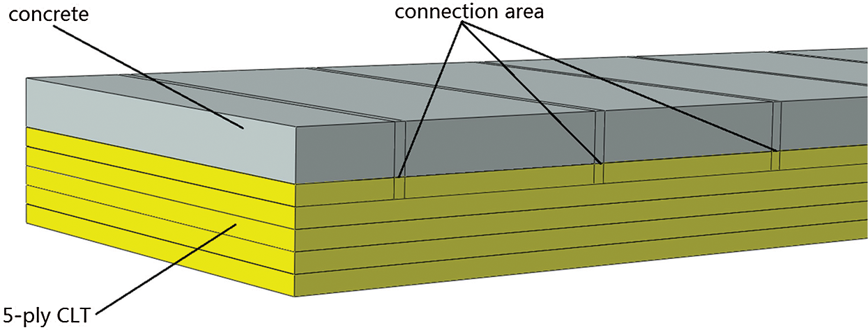
Figure 11: The numerical model of full-scale TCC floor
The model of the TCC slab consisted of the concrete and CLT slab. The cross lamination of CLT was simulated by assigning the material direction of each ply timber.
‘Tie’ contact was adopted between all wood panels. For the thermal analysis, the surfaces between the concrete and timber were interrelated by the tie contact. The contact properties of these surfaces for the mechanical analysis were presented in Section 4.2. The bottom layers of CLT were deactivated during the fire simulation to simulate the char fall-off of timber. The first, second and third layers of CLT were deactivated by creating the model change interaction at 90, 120 and 180 min of fire exposure [7], respectively.
Due to developing a quarter of the numerical model, two boundary conditions were required for symmetry planes. The three translations of all the nodes that correspond to support areas was set to values of zero displacements to simulated the supports at the bottom of timber. The fire loading was simulated by one-dimensional heat transfer throughout the TCC slab section under standard CAN/ULC-S101 fire curve. The temperature filed from the thermal analysis was input into the structural model to conduct structurally analysis. A pressure of 2.4 kPa was applied to the upper surface of the concrete to simulate the live load. The self-weight loads of the TCC slab were also applied to the numerical model.
4.2 Simplified Model of Screw Connection
Considering the reliability and efficiency of the TCC slab models, the surfaces of all the nodes that correspond to the connected areas of screw were simplified as a special cohesive contact [38], as shown in Fig. 12. Since the screws along the width were spaced at 102 mm, a 102 mm × 20 mm rectangular area at the interface between the timber and concrete was adopted as cohesive contact. As only quarter of the model was built, the cohesive contact areas were adjusted to 51 mm × 20 mm.
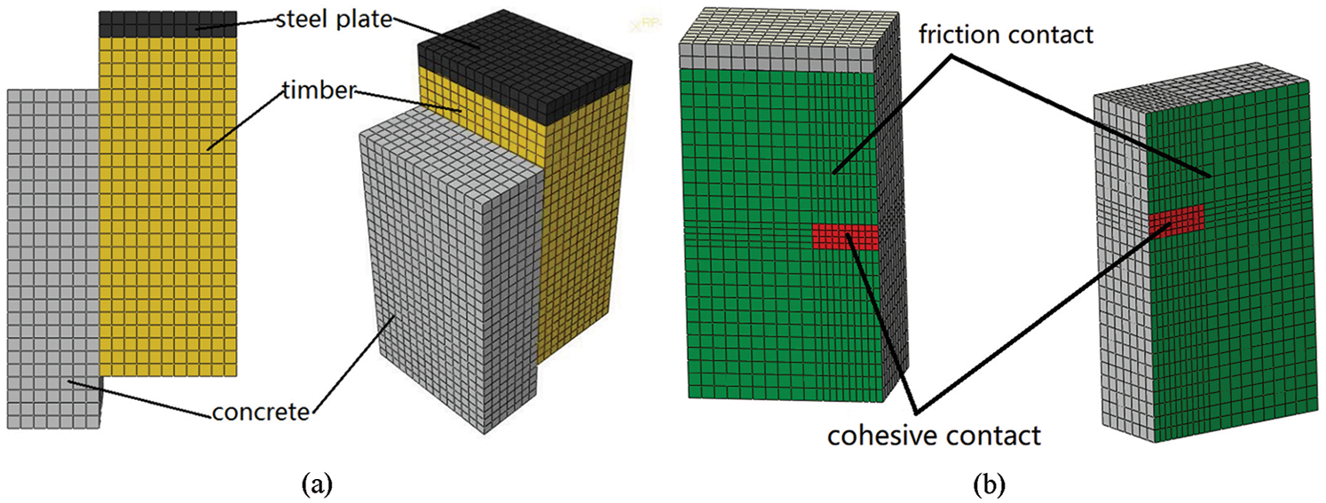
Figure 12: (a) The quarter of simplified model, (b) the contact of the surfaces between the timber and concrete
The cohesive contact parameters were calibrated, according to modifying the slip stiffness and shear strength of the simplified model. The shear strength Fmax is defined by the peak load of the load-slip curves. The slip modulus Ku at ultimate limit state is determined from the load-slip curves according to the formulation offered by [39]:
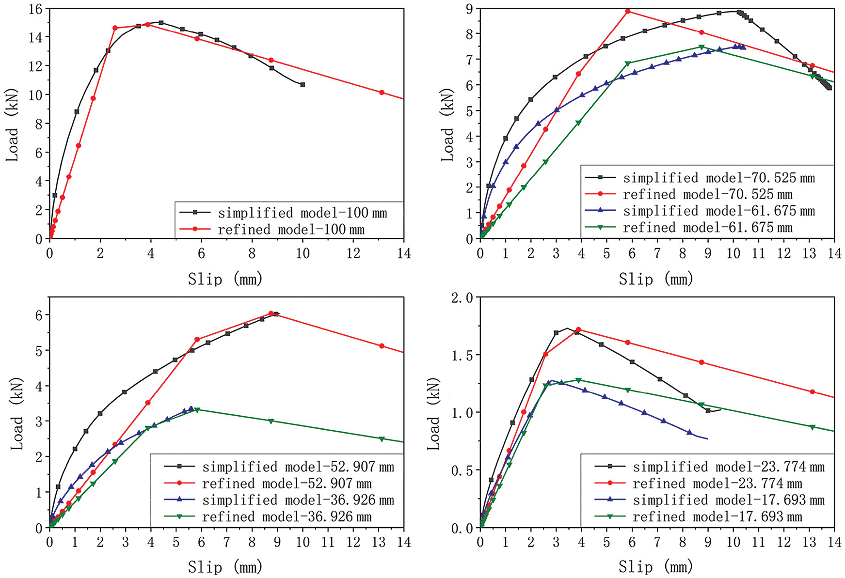
Figure 13: The load-slip curves of refined and simplified models for different effective penetration length

4.3 Validation of the FE Full-Scale Model
As shown in Fig. 14, the deflection-time curves of the numerical simulation and test [7] was consistent. It can be observed that the FE model could provide good predictions of displacement at the initial stage. However, this FE model overestimates the deflection when the burning time is from 96 to 156 min. The simulated deflection increased sharply at 170 min until the TCC slab failed at 184 min, while ultimate fire-resistance time of test was 214 min. A comparison between the fire resistances obtained from the numerical simulations and experimental tests shows that the deviation of numerical simulation is up to −14.02%. The reason is that the delamination simulated by the FE model is assumed as the whole layer of the laminate exposed to fire falling off, while the delamination during the test is a local phenomenon. Therefore, the numerical model of TCC slab overestimates the weakening structural performance by fire and underestimates the fire resistance.
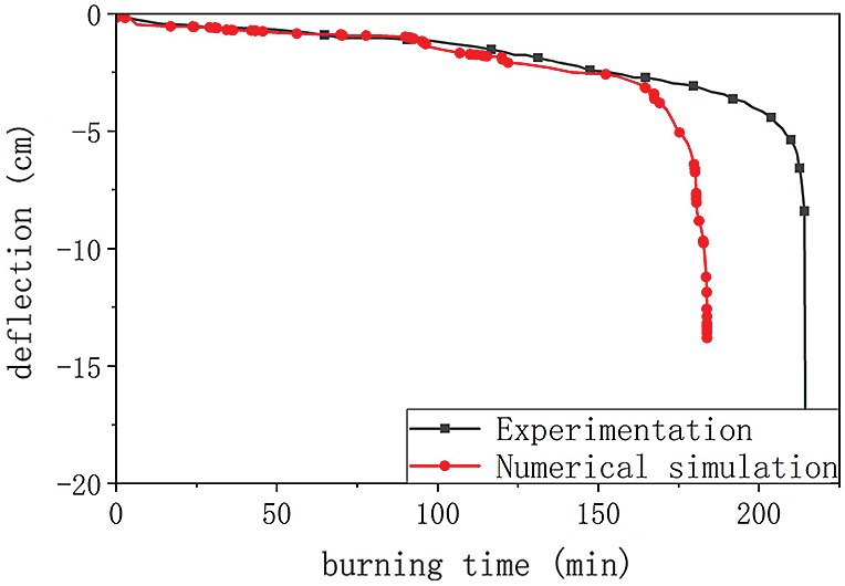
Figure 14: Numerical model of TCC floor and experimental deflection-time curves
In this paper, the structural performance of the TCC connections and the fire performance of the TCC connections and TCC slabs were numerically investigated. Besides, the obtained reduction law was also applied to the full-scale FE model to investigate the fire performance of TCC slab. The main conclusion can be drawn as follows:
(1) A FE model was proposed to predict the connection behavior of concrete-timber-concrete push-out specimens. The proposed FE model with different screw diameters and penetration lengths was validated by existing experimental results. The developed numerical model shows the capacity to describe the load slip behavior of push-out specimens. Although the maximum load of the numerical model was predicted accurately, the initial stiffness was overestimated. The relative error of the slip modulus was acceptable except + 29.97% relative error for specimen L80-10.
(2) A sequentially coupling thermal stress model was developed to predict the connection behavior of push-out specimens under different temperatures. The reduction law of the joint strength Fmax and slip modulus KS with the burning time were proposed. Considering the usability of reduction law, the relationship between the effective penetration length and reduction coefficient was established.
(3) A sequentially coupling thermal stress model combined with the proposed reduction law of connection performance was used to predict the fire performance of the TCC slab. Comparing load-slip curves, a simplified push-out model with a special cohesive contact to replace the screw connection was validated. For computational efficiency, this simplified push-out model was applied to the composite slab model. The TCC slab deflection as a function of standard fire exposure time was predicted by this numerical model in good agreement with the experimental results. However, a comparison between the fire-resistance time obtained from the numerical simulations and experiment shows that the deviation of numerical simulation is up to −14.02%.
The sequentially coupling thermal stress model with the reduction law proposed in this paper can provide good predictions of the fire performance and fire-resistance time. The further research is necessary, especially more detailed and extensive experimental results are needed to verify the reliability of the proposed model. Finally, more experiments for TCC slab should be conducted to better validate the numerical model.
Acknowledgement: The authors gratefully acknowledge the financial support provided by National Natural Science Foundation of China (Grant No. 5187082769).
Funding Statement: This study was funded by National Natural Science Foundation of China (Grant No. 5187082769).
Conflicts of Interest: The authors declare that there is no conflict of interest to report regarding the present study.
1. Aicher, S., Dill-Longer, G. (2005). Effect of lamination anisotropy and lay-up in glued-laminated timbers. Journal of Structural Engineering, 131(7), 1095–1103. DOI 10.1061/(ASCE)0733-9445(2005)131:7(1095). [Google Scholar] [CrossRef]
2. Ganey, R., Berman, J., Akbas, T., Loftus, S., Dolan, J. D. et al. (2017). Experimental investigation of self-centering cross-laminated timber walls. Journal of Structural Engineering, 143(10), 04017135. DOI 10.1061/(ASCE)ST.1943-541X.0001877. [Google Scholar] [CrossRef]
3. Yeoh, D., Fragiacomo, M., Franceschi, M. D., Boon, K. H. (2011). State of the art on timber-concrete composite structures: Literature review. Journal of Structural Engineering, 137(10), 1085–1095. DOI 10.1061/(ASCE)ST.1943-541X.0000353. [Google Scholar] [CrossRef]
4. Xie, Z., Hu, X. M., Du, H., Zhang, X. Y. (2020). Vibration behavior of timber-concrete composite floors under human-induced excitation. Journal of Building Engineering, 32, 101744. DOI 10.1016/j.jobe.2020.101744. [Google Scholar] [CrossRef]
5. Zhang, X. Y., Hu, X. M., Gong, H. W., Zhang, J., Lv, Z. C. et al. (2020). Experimental study on the impact sound insulation of cross laminated timber and timber-concrete composite floors. Applied Acoustics, 161, 107173. DOI 10.1016/j.apacoust.2019.107173. [Google Scholar] [CrossRef]
6. Hozjan, T., Bedon, C., Ogrin, A., Cvetkovska, M., Klippel, M. (2019). Literature review on timber–Concrete composite structures in fire. Journal of Structural Engineering, 145(11), 04019142. DOI 10.1061/(ASCE)ST.1943-541X.0002418. [Google Scholar] [CrossRef]
7. Osborne, L., Sc, M. A. (2015). Fire resistance of long span composite wood-concrete floor systems (Project Rep). FPInnovations Project No. 301009649. Montréal, Quebec, Canada: FPInnovations. [Google Scholar]
8. Caldova, E., Vymlatil, P., Wald, F., Kuklikova, A. (2014). Timber steel fiber-reinforced concrete floor slabs in fire: Experimental and numerical modeling. Journal of Structural Engineering, 141(9), 04014214. DOI 10.1061/(ASCE)ST.1943-541X.0001182. [Google Scholar] [CrossRef]
9. Dias, A., Cruz, H., Lopes, S., Kuilen, J. W. G. (2004). Experimental shear-friction test on dowel type fastener timber-concrete joints. World Conference on Timber Engineering Finland. [Google Scholar]
10. Du, H., Hu, X. M., Xie, Z., Wang, H. C. (2019). Study on shear behavior of inclined cross lag screws for glulam-concrete composite beams. Construction and Building Materials, 224, 132–143. DOI 10.1016/j.conbuildmat.2019.07.035. [Google Scholar] [CrossRef]
11. Marchi, L., Scotta, R., Pozza, L. (2017). Experimental and theoretical evaluation of TCC connections with inclined self-tapping screws. Materials and Structures, 50(3), 180. DOI 10.1617/s11527-017-1047-1. [Google Scholar] [CrossRef]
12. Mirdad, M. A. H., Chui, Y. H. (2019). Load-slip performance of mass timber panel-concrete (MTPC) composite connection with self-tapping screws and insulation layer. Construction and Building Materials, 213(20), 696–708. DOI 10.1016/j.conbuildmat.2019.04.117. [Google Scholar] [CrossRef]
13. Mirdad, M. A. H., Chui, Y. H. (2010). Stiffness prediction of mass timber panel-concrete (MTPC) composite connection with inclined screws and a gap-scienceDirect. Engineering Structures, 207, 110215. DOI 10.1016/j.engstruct.2020.110215. [Google Scholar] [CrossRef]
14. Avez, C., Descamps, T., Serrano, E., Léoskool, L. (2016). Finite element modelling of inclined screwed timber to timber connections with a large gap between the elements. European Journal of Wood and Wood Products, 74, 467–471. DOI 10.1007/s00107-015-1002-1. [Google Scholar] [CrossRef]
15. Bedon, C., Fragiacomo, M., Tamagnone, G. (2019). Numerical analysis of timber-to-timber joints and composite beams with inclined self-tapping screws. Composite Structures, 207, 13–28. DOI 10.1016/j.compstruct.2018.09.008. [Google Scholar] [CrossRef]
16. Resch, E., Kaliske, M. (2010). Three-dimensional numerical analyses of load-bearing behavior and failure of multiple double-shear dowel-type connections in timber engineering. Computers & Structures, 88(3), 165–177. DOI 10.1016/j.compstruc.2009.09.002. [Google Scholar] [CrossRef]
17. Kuilen, J. W. V. D., Dejong, M. (2004). 3D-numerical modelling of DVW-reinforced joints. World Conference on Timber Engineering Finland. [Google Scholar]
18. Dias, A. M. P. G., Kuilen, J. W. V. D., Lopes, S., Cruz, H. (2007). A non-linear 3D FEM model to simulate timber-concrete joints. Advances in Engineering Software, 38(8), 522–530. DOI 10.1016/j.advengsoft.2006.08.024. [Google Scholar] [CrossRef]
19. Oudjene, M., Meghlat, E. M., Ait-Aider, H., Lardeurc, P., Khelifa, M. et al. (2018). Finite element modelling of the nonlinear load-slip behaviour of full-scale timber-to-concrete composite T-shaped beams. Composite Structures, 196, 117–126. DOI 10.1016/j.compstruct.2018.04.079. [Google Scholar] [CrossRef]
20. Bedon, C., Fragiacomo, M. (2018). Timber-concrete composite structures in fire conditions-finite element numerical modelling of tensile tests. Final Conference COST FP1404 “Fire Safe Use of Bio-Based Building Products”, Zurich. [Google Scholar]
21. Palma, P., Frangi, A. (2017). Modelling the fire resistance of steel-to-timber dowelled connections loaded perpendicularly to the grain. Fire Safety Journal, 107, 54–74. DOI 10.1016/j.firesaf.2017.12.001. [Google Scholar] [CrossRef]
22. Frangi, A., Knobloch, M., Fontana, M. (2010). Fire design of timber-concrete composite slabs with screwed connections. Journal of Structural Engineering, 136(2), 219–228. DOI 10.1061/(ASCE)ST.1943-541X.0000101. [Google Scholar] [CrossRef]
23. Auclair, S. C., Sorelli, L., Salenikovich, A. (2016). Simplified nonlinear model for timber-concrete composite beams. International Journal of Mechanical Sciences, 117, 30–42. DOI 10.1016/j.ijmecsci.2016.07.019. [Google Scholar] [CrossRef]
24. Dagenais, C., Ranger, L., Auclair, S. C. (2016). Understanding fire performance of wood-concrete composite floor systems. World Conference on Timber Engineering Austria. [Google Scholar]
25. CSA O86-14 (2014). Engineering design in wood. Mississauga, Ontario, Canada, CSA Group. [Google Scholar]
26. EN 1993-1-4: 2006, Eurocode3 (2006). Design of steel structures, part 1–4: General rules-supplementary rules for stainless steels. Brussels: European Committee for Standardization. [Google Scholar]
27. Al-Sammari, A. T., Clouston, P. L., Brea, S. F. (2018). Finite-element analysis and parametric study of perforated steel plate shear connectors for wood-concrete composites. Journal of Structural Engineering, 144(10), 04018191. DOI 10.1061/(ASCE)ST.1943-541X.0002188. [Google Scholar] [CrossRef]
28. EN 338-2016 (2016). Structural timber-strength classes. Brussels: European Committee for Standardization. [Google Scholar]
29. Chatzistergos, P. E., Magnissalis, E. A., Kourkoulis, S. K. (2010). A parametric study of cylindrical pedicle screw design implications on the pullout performance using an experimentally validated finite-element model. Medical Engineering & Physics, 32(2), 145–154. DOI 10.1016/j.medengphy.2009.11.003. [Google Scholar] [CrossRef]
30. Chatzistergos, P. E., Magnissalis, E. A., Kourkoulis, S. K. (2014). Numerical simulation of bone screw induced pretension: The cases of under-tapping and conical profile. Medical Engineering & Physics, 36(3), 378–386. DOI 10.1016/j.medengphy.2013.12.009. [Google Scholar] [CrossRef]
31. EN 26891-1991 (1991). Timber structures-joints made with mechanical fasteners-general principle for the determination of strength and deformation characteristics. Brussels: European Committee for Standardization. [Google Scholar]
32. EN 1995-1-2: 2004, Eurocode5 (2004). Design of timber structures, part 1–2: General-structural fire design. Brussels, European Committee for Standardization. [Google Scholar]
33. EN 1993-1-2: 2005, Eurocode3 (2005). Design of steel structures, part 1–2: General rules-structural fire design. Brussels, European Committee for Standardization. [Google Scholar]
34. EN 1994-1-2: 2004, Eurocode 4 (2004). Design of composite and concrete structures, part 1–2: Structural fire design. Brussels, European Committee for Standardization. [Google Scholar]
35. CAN/ULC-S101 (2014). Standard methods of fire endurance test of building construction and materials. Ottawa: ULC Standards. [Google Scholar]
36. EN 1991-1-5: 2004, Eurocode1 (2004). Actions on structures, part 1–5: General actions-thermal actions. Brussels: European Committee for Standardization. [Google Scholar]
37. Schaffer, E. L., Marx, C. M., Bende, D. A., Woeste, F. E. (1986). Strength validation and fire endurance of glued-laminated timer beams. Research Paper FPL 467. Forest Products Laboratory, USA. [Google Scholar]
38. Caldová, E., Blesák, L., Wald, F., Kloiber, M., Urushadze, S. et al. (2014). Behaviour of timber and steel fibre reinforced concrete composite constructions with screwed connections. Wood Research, 59(4), 639–660. http://www.woodresearch.sk/wr/201404/11.pdf. [Google Scholar]
39. Gerber, A. R. (2016). Timber-concrete composite connectors in flat-plate engineered wood products (Ph.D. Thesis). University of British Columbia, Canada. [Google Scholar]
 | This work is licensed under a Creative Commons Attribution 4.0 International License, which permits unrestricted use, distribution, and reproduction in any medium, provided the original work is properly cited. |