| Journal of Renewable Materials |
DOI: 10.32604/jrm.2022.020671
ARTICLE
Influence of the Loading Protocol and Loading Rate on the Characteristics of Timber Nail Joints
1Department of Civil Engineering, University of Victoria, Victoria, V8P 5C2, Canada
2Advanced Building Systems, FPInnovations, Vancouver, V6T 1W5, Canada
*Corresponding Author: Lina Zhou. Email: linazhou@uvic.ca
Received: 06 December 2021; Accepted: 22 February 2022
Abstract: Nail joints are one of the key components that control the lateral performance of light wood frame shear walls. In previous experimental studies, researchers have used different loading rates, which failed specimens from less than a minute to more than an hour, to study the characteristics of nail joints. Moreover, there have been different loading protocols used for testing of timber nail joints or shear walls. Although some efforts have been made to address this subject, it is still unclear how the loading protocol and loading rate may influence the performance of nail joints. In this study, a total of 96 nail joints tests were carried out under monotonic and reversed-cyclic loads at three different loading rates, and under three different loading protocols (ISO, CUREE and SPD). The results of the test revealed that the loading rate did not have a noticeable effect on the mechanical properties of nail joints, while the loading protocol did influence those properties. Especially, protocols with larger cumulative damage demands lead to lower ultimate displacement and ductility of nail joints.
Keywords: Loading protocol; loading rate; timber nail joint; reversed-cyclic load; monotonic load
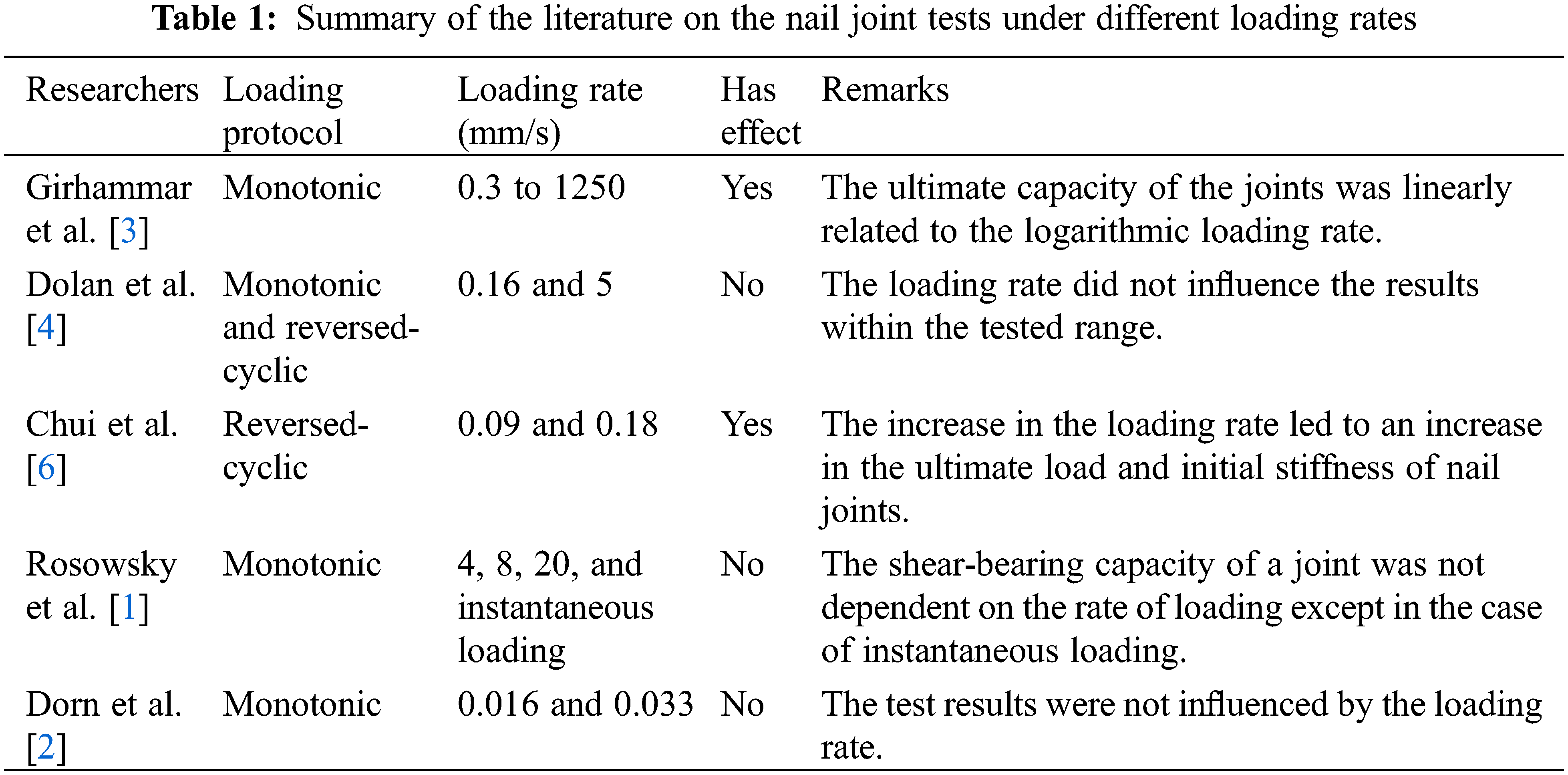
Light wood frame buildings are the predominant type of structures for residential buildings in North America. The lateral load capacity of light wood frame structures is provided by light wood frame shear walls, which are made of dimension lumber, sheathing panels, and nails. The sheathing-to-framing nail joints play an important role in determining the lateral load resistance of the shear walls. So far, many experimental studies have been carried out on nail joints used in light wood frame shear walls. In these tests, different loading rates were used, which caused the failure of nail joints in less than a minute in some studies and more than an hour in other studies [1,2]. The conclusions reported by other researchers regarding the effect of loading rate on the performance of nail joint are not consistent (Table 1). It is not clear whether these test results derived under various loading rates are comparable, and what is the effect of the loading rate on the performance of timber nail joints. Meanwhile, various loading protocols have been used for the reversed-cyclic test of nail joints and there is no literature available on the effect of these loading protocols on the performance of nail joints, as previous research on the effect of loading protocol effect were mainly focused on shear wall systems.
Girhammar et al. [3] investigated the effect of loading rate on timber nail joints under monotonic load, with loading rates varying from 0.3 mm/s to 1250 mm/s. Their experiments showed that the increase in loading rate led to a higher shear capacity of nail joints. Additionally, they concluded that the increase in shear capacity of the joints was linearly related to the logarithmic loading rate. Dolan et al. [4] examined two different loading rates for the reversed-cyclic loading tests, 10 mm/min (0.16 mm/s) and 300 mm/min (5 mm/s). They concluded that the respective load-displacement curves under the two loading rates were statistically identical; therefore, within the tested range, the loading rate did not influence the results. In Dolan et al.’s tests, the lower loading rate was selected based on the experiments done by Foschi [5] while the higher loading rate was the maximum capacity of the hydraulic actuator. Chui et al. [6] conducted a study on nail joints to determine the effect of loading rate on the performance of the nail joints. Their study revealed that the increase in the loading rate would lead to an increase in the maximum load and initial stiffness of nail joints, which was also reported by Soltis et al. [7]. Rosowsky et al. [1] studied the effect of loading rate on nail joints under monotonic load (4 mm/s, 8 mm/s, 20 mm/s, and instantaneous loading). The loading time to fail a joint varied between a fraction of a second to 4 seconds. Their study determined that the shear capacity of a nail joint was not dependent on the rate of loading except in the case of instantaneous loading. Dorn et al. [2] conducted an experimental study on dowel-type connections. They tested a range from 0.01 mm/s to 0.03 mm/s for the loading rate and explained that the test results were not influenced by the loading rate. Table 1 summarizes the literature on the nail joint tests under different loading rates.
The loading rate suggested by timber joint standards also vary a lot. BS EN 26891 [8] suggested that the total monotonic testing time is about 10 to 15 minutes for the introduced loading procedure. BS EN 12512 [9] recommended the loading rate to be in the range of 0.02 mm/s to 0.2 mm/s for testing fasteners under reversed-cyclic loading. ISO 16670 [10] stipulates that the loading rate for testing joints with mechanical fasteners is between 0.1 mm/s and 10 mm/s for reversed-cyclic loading, respectively. ASTM D1761 [11] prescribed that the maximum load of fasteners in wood should be reached between 5 to 20 min. It explained that the loading speed of 0.015 mm/s
There has been no research done on the effect of loading protocols on the performance of wood nail joints. Given the fact that nail joints govern the performance of wood shear walls, a review of research related to wood shear walls under different loading protocols is discussed. For testing light wood frame shear walls, various loading protocols have been developed and used by researchers. There are three well-established and widely used protocols specified in ASTM E2126 [12]: ISO, sequential-phased displacement (SPD), and CUREE basic loading protocol. In the ISO loading protocol, two displacement patterns are defined based on the ultimate displacement. Three cycles are repeated at the same amplitude of each displacement increment in the second pattern (Fig. 1a). The SPD loading protocol also comprises two displacement patterns. The main pattern of the SPD loading protocol includes seven cycles in each displacement increment that consists of a reduced amplitude for the first four cycles and a recovered constant amplitude for the last three cycles (Fig. 1b). Lastly, the CUREE loading protocol includes low-amplitude initiation cycles and primary cycles. The primary cycles consist of three cycles with the last two having a reduced amplitude (Fig. 1c). The incremental displacements of all three loading protocols are defined as a percentage of the reference displacement. Fig. 1 shows the ISO, SPD and CUREE loading protocols.
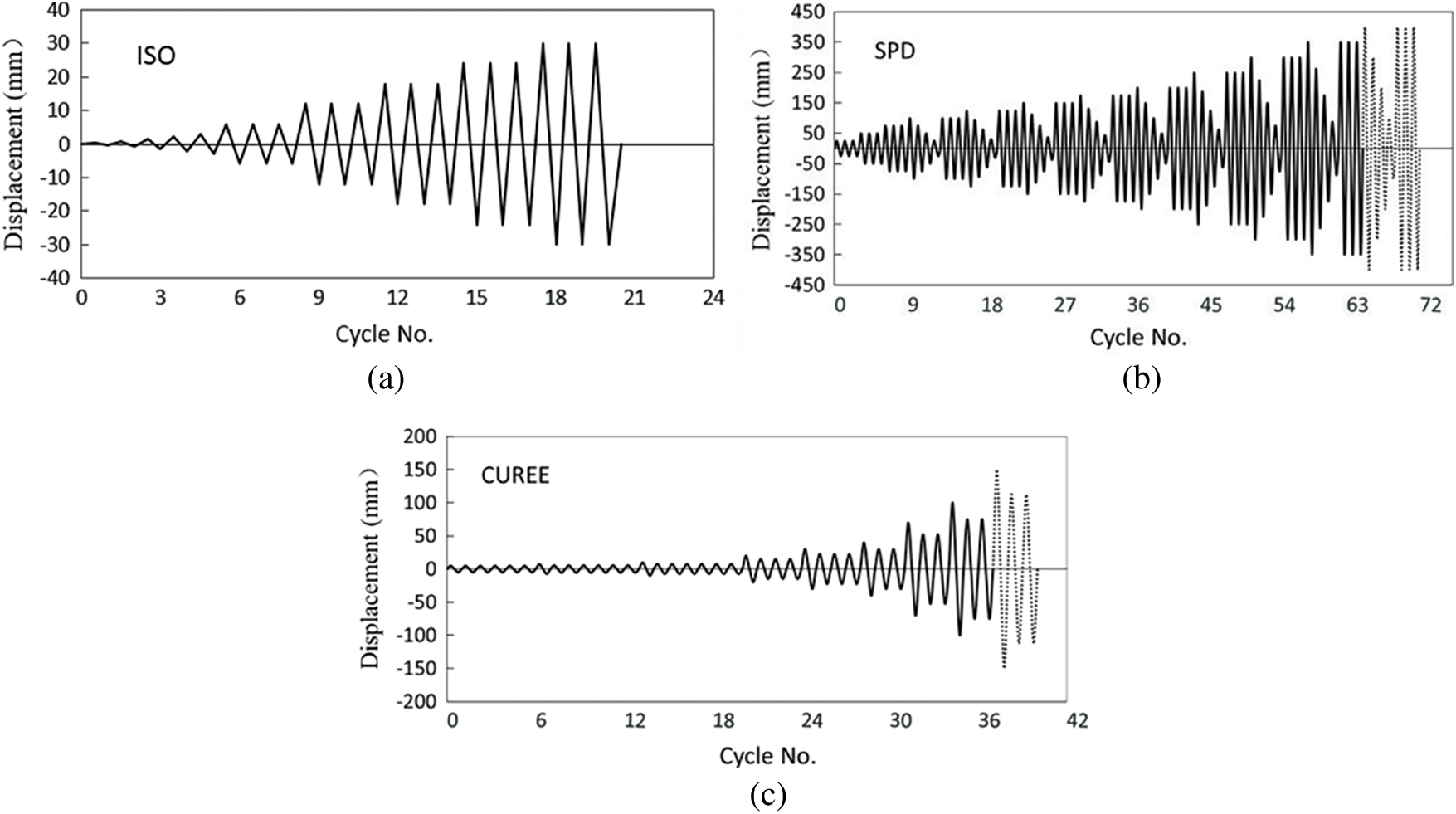
Figure 1: Patterns of loading protocols: (a) ISO, (b) SPD, and (c) CUREE
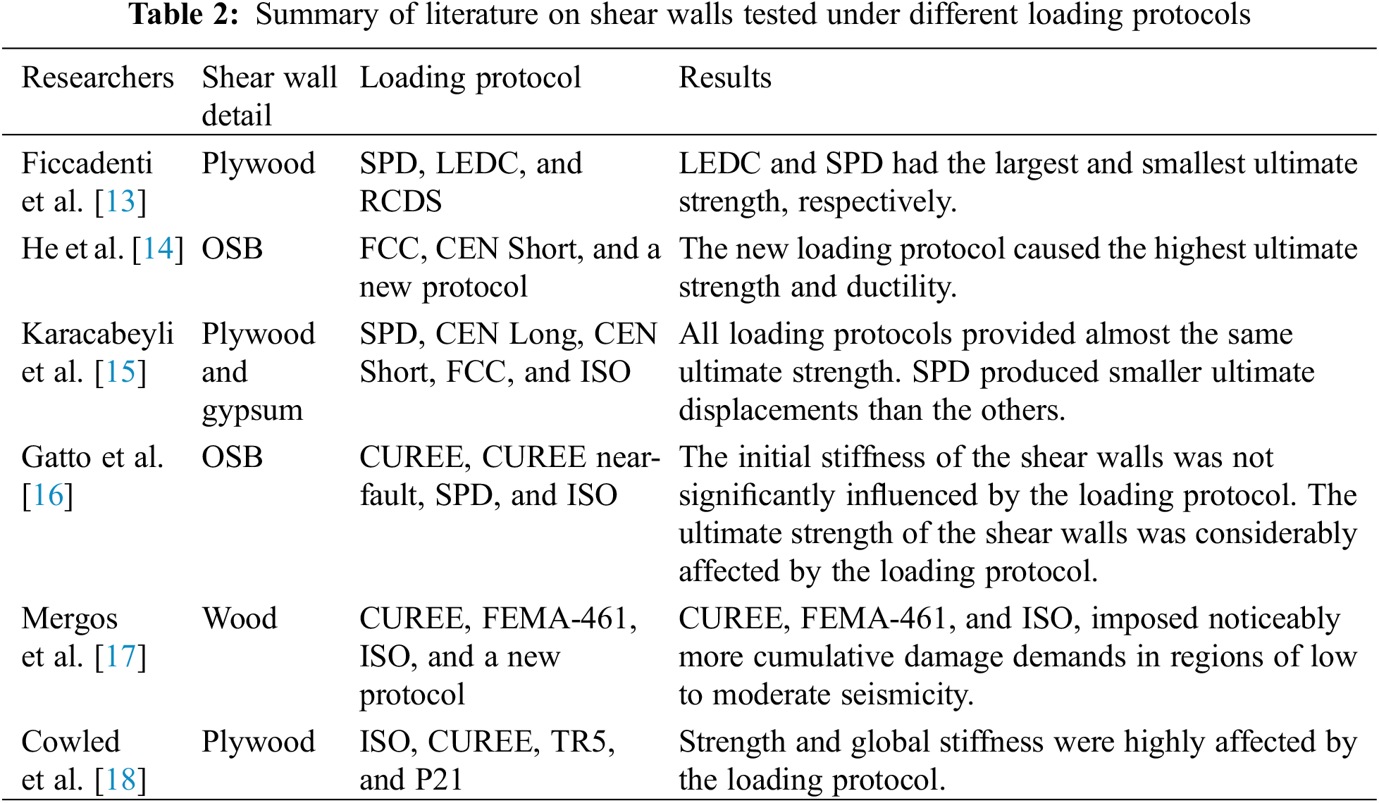
Ficcadenti et al. [13] conducted tests on light wood frame shear walls under three different loading protocols: SPD, large excursion displacement sequence (LEDS), and reduced cyclic displacement sequence (RCDS). LEDS loading protocol is similar to the SPD loading protocol but the first four cycles are eliminated in order to simulate huge pulses in near-field earthquakes. RCDS loading protocol is also similar to the SPD loading protocol but the last three cycles in each displacement increment are eliminated to minimize the nail failure. The results revealed that the walls under LEDS loading protocol had the largest ultimate strength, whereas the ones under the SPD loading protocol had the smallest ultimate strength. Moreover, they found that the ultimate displacement was not considerably affected by the loading protocols. He et al. [14] carried out an experimental investigation on the effect of the loading protocol on wood-based shear walls. Forintek Canada crop (FCC), Committee European Normalization (CEN) short protocol, and a newly developed loading protocol were examined. Different nail failure modes were observed under different loading protocols. The result of the experiments indicated that under FCC protocol, which had a redundant number of cycles, nail failure was the dominant failure mode, however, this failure mode rarely takes place during a real earthquake. On the other hand, CEN short protocol did not present an expected and reasonable behavior of the shear wall. The newly developed loading protocol was able to reasonably demonstrate the behavior of shear walls under seismic loads. They reported that the shear wall tested with the newly developed loading protocol experienced the highest ultimate strength and ductility. Karacabeyli et al. [15] investigated the performance of shear walls under different loading protocols: SPD, CEN Long protocol, CEN short protocol, FCC, and ISO. They reported that all of the five loading protocols provided approximately the same ultimate strength (with a maximum of 10% difference); however, SPD loading protocol produced smaller ultimate displacements compared with the other loading protocols (with a maximum of 40% difference). Gatto et al. [16] carried out a series of experiments to compare the effects of various loading protocols on the cyclic response of light wood shear walls. Monotonic loading tests were conducted as well as reversed-cyclic loading tests under CUREE, CUREE near-fault, SPD, and ISO loading protocols. Their findings confirmed that the initial stiffness of the shear walls was not significantly influenced by the applied loading protocol, while the ultimate strength of the shear walls was considerably affected by the loading protocol. For instance, in the case of SPD loading protocol, the corresponding averaged ultimate strength and ultimate deformation were 25% and 47% less than those under CUREE loading protocol, respectively. Mergos et al. [17] developed a new loading protocol suitable for regions of low to moderate seismicity. They argued that the existing loading protocols, CUREE, FEMA-461, and ISO, imposed noticeably more cumulative damage demands, leading to an underestimation of the lateral load capacity and especially the ultimate deformation of the specimens in regions of low to moderate seismicity. Cowled et al. [18] conducted experiments on the shear walls under three monotonic and four cyclic loading protocols, namely ISO, CUREE, TR5, and P21. Their experiments revealed that the shear wall strength and global stiffness were highly affected by the loading protocols. Table 2 summarizes the literature on the shear wall tests under different loading protocols.
Although a wide variety of loading rates and loading protocols have been suggested by different standards or examined by different researchers, their effect on the characteristics of timber nail joints needs further investigation. In this study, a reasonable range of loading rates and commonly used loading protocols were adopted for both monotonic and reversed-cyclic loading tests to investigate the effect of loading rates and protocols on the characteristics of nail joints.
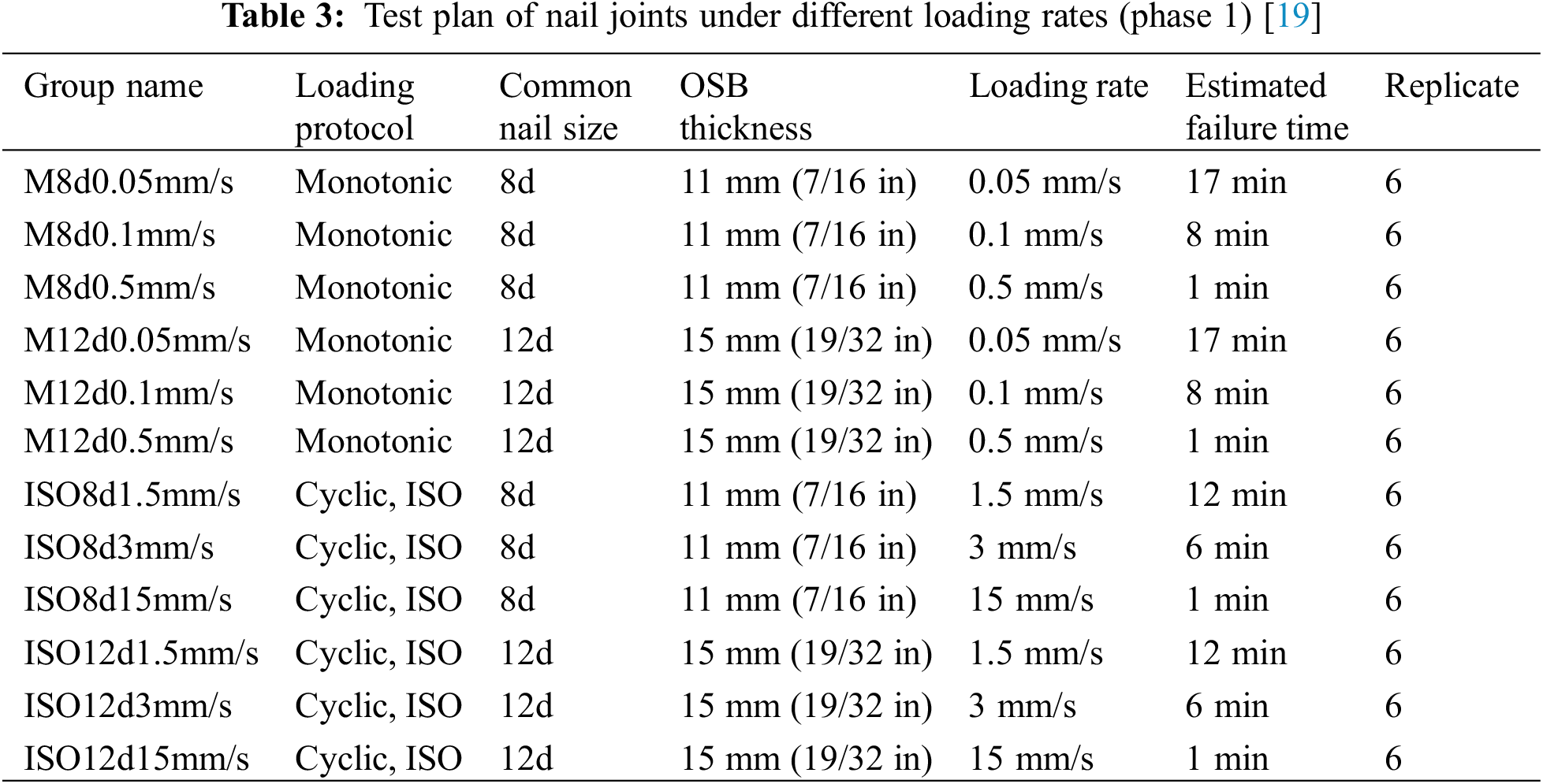
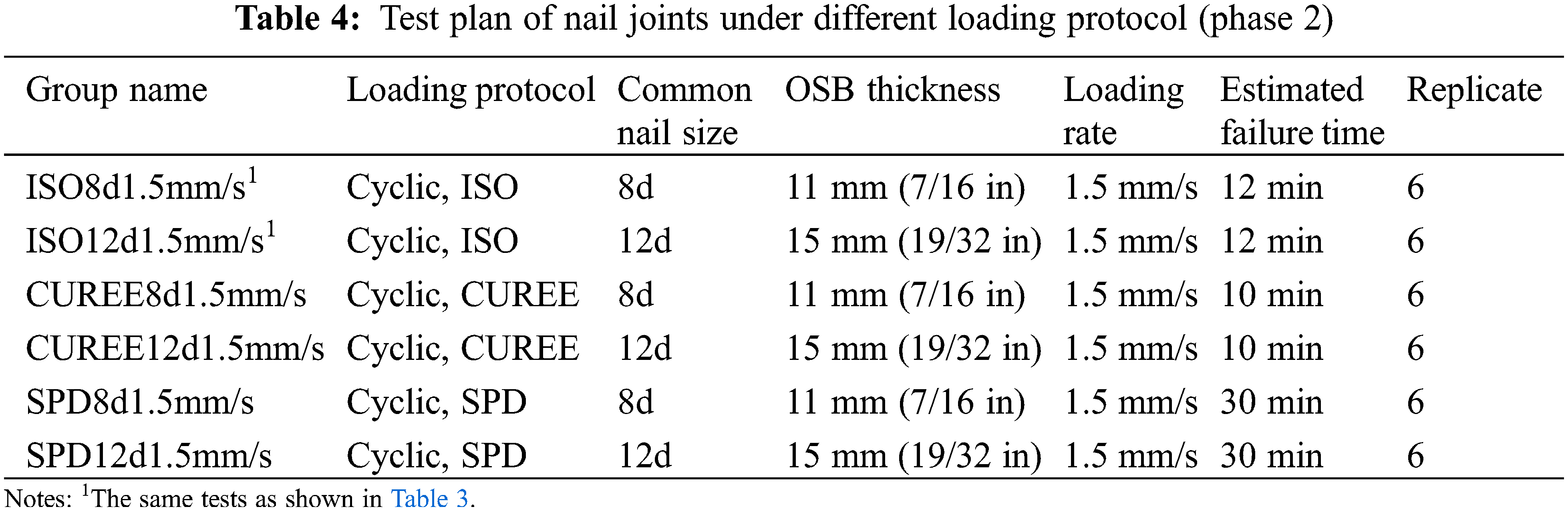
In this project, a total number of 96 nail joints specimens were tested. The nail joints were made of 2 × 4 in. (38 × 89 mm) No. 2 and better grade spruce-pine-fir (SPF) dimension lumber, oriented strand board (OSB), and common nails. The lumber was stored in an environmental chamber at 20°C and 65% relative humidity for a few weeks. The selected lumber had a specific gravity within the range of 0.42 ± 10%. Two types of sheathing nail joints were used: common 8d nail with 11 mm thickness OSB (rated as 1R24/2F16) and common 12d nail with 15 mm thickness OSB (rated as 2R40/2F20) (Tables 3 and 4). The 8d common nail has a shank length of 63.5 mm (2.5 in) and a diameter of 3.33 mm (0.131 in), and 12d common nail has a shank length of 82.6 mm (3.25 in) and a diameter of 3.76 mm (0.148 in). The OSB panel was attached to the lumber by two common nails. Fig. 2 illustrates the details of the nail joints specimens. Two linear variable differential transformers (LVDTs) were attached to the specimen to measure the relative displacement between the lumber and the sheathing panel. The test schedule consisted of two phases. In the first phase, 72 specimens, including monotonic and reversed-cyclic loading (ISO loading protocol), were tested. The main objective of this phase was to investigate the effect of loading rate on the mechanical properties of nail joints. Specimens were tested under monotonic loading at rates of 0.05 mm/s, 0.1 mm/s, and 0.5 mm/s and under reversed-cyclic loading at rates of 1.5 mm/s, 3 mm/s, and 15 mm/s (Table 3). The group names listed in Table 3 indicate the configurations of nail joints. For monotonic tests, the above-mentioned loading rates were selected to have the samples fail in about 20 min for the lowest rate to control the total testing time in a reasonable period and 1 min for the fastest rate to represent the duration of a real earthquake. The rates were set based on the ultimate displacement of 30 mm obtained from trial tests. In the case of reversed-cyclic loading tests, the three loading rates were estimated so that the specimen failure occurred with approximately the same duration of testing under the three monotonic loading rates, respectively. Since the total displacement of reversed-cyclic loading tests is much larger than that of monotonic tests, the chosen loading rates for reversed-cyclic loading tests were considerably larger than those of monotonic tests. In the second phase, additional 24 nail joints specimens under CUREE, and SPD cyclic loading protocols [12] described in the introduction of the paper were tested and compared their performance to the ones tested under ISO loading protocol in phase 1 to investigate the effect of loading protocol on the mechanical properties of nail joints (Table 4). Among these three loading protocols, SPD is expected to have the highest cumulative damage demand, while CUREE has the least demand.
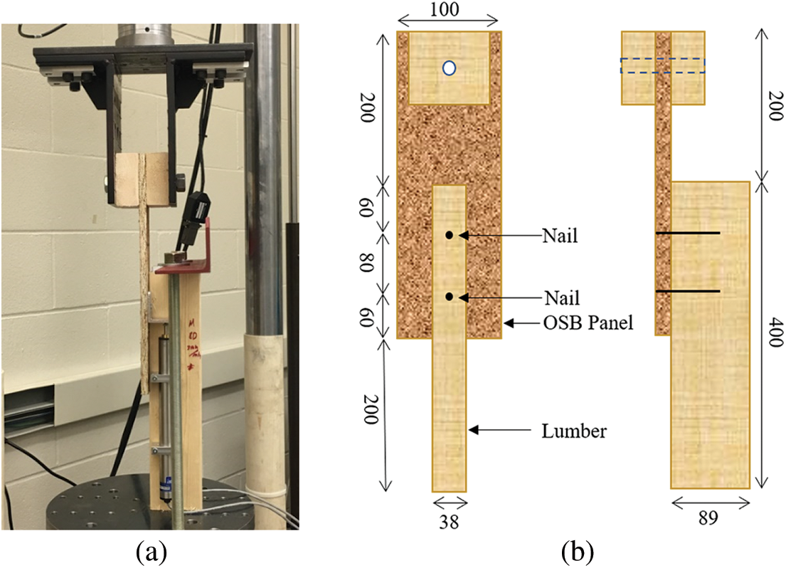
Figure 2: Nail joint test: (a) test setup; (b) schematic view of the specimens (unit: mm)
All tested specimens had a ductile failure. In other words, all nail joints failed as a result of the yielding of nails under both monotonic and reversed-cyclic loading. The failure took place through gradual pullout of the nail from the lumber, which was accompanied by nail bending (Fig. 3a). In the case of SPD loading protocol, all nail joints experienced nail breakage (Fig. 3b). Nevertheless, no nail breakage was observed in other loading groups (Fig. 3a). In some samples of CUREE8d (Table 4), where the thickness of the sheathing panel was relatively small, 11 mm, crushing of wood fibers around the nail head occurred (Fig. 3c). This is mostly because of the nail head rotation during testing of joints with thin sheathing panels.
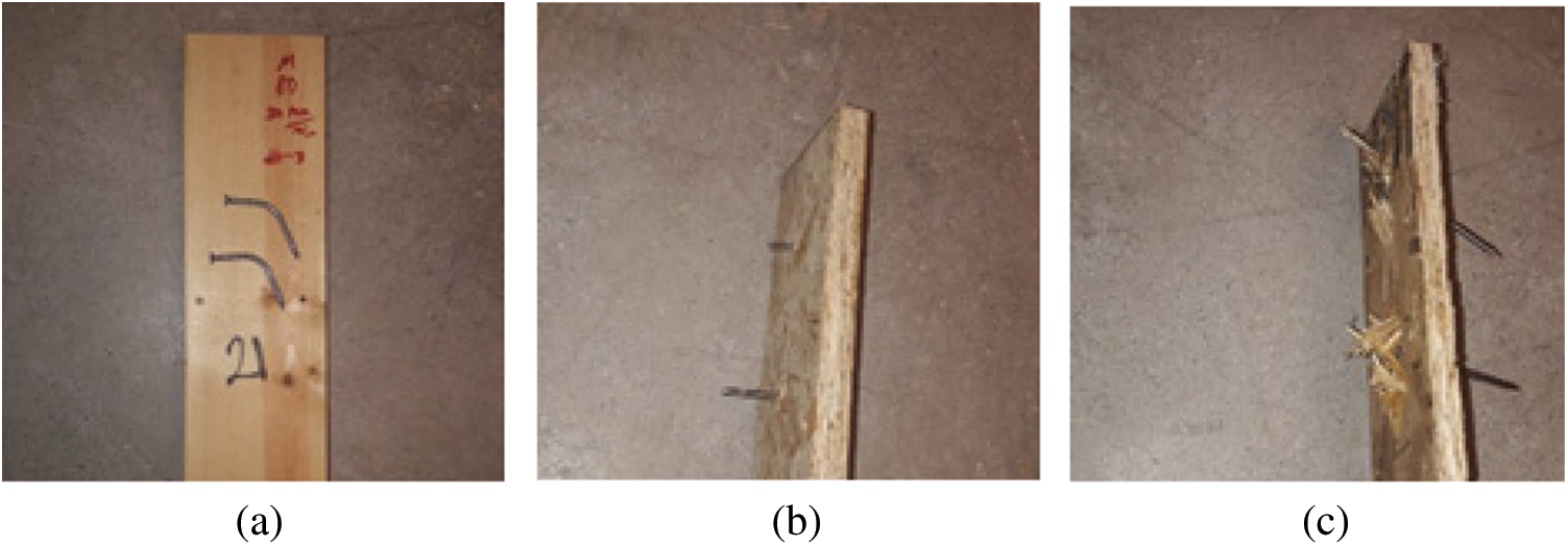
Figure 3: Failure modes of nail joints: (a) nail pull out and bending, (b) nail breakage (c) wood crushing around nails
In this phase of the study, the effect of loading rate for both monotonic and reversed-cyclic loading tests was investigated. As mentioned earlier, three different loading rates for both monotonic and reversed-cyclic loading rates were examined and the results are presented in this section. Fig. 4 illustrates the averaged load-displacement curves of monotonic tests and the averaged backbone curves of reversed-cyclic tests, respectively. The backbone curves were obtained following ASTM E2126 [12].
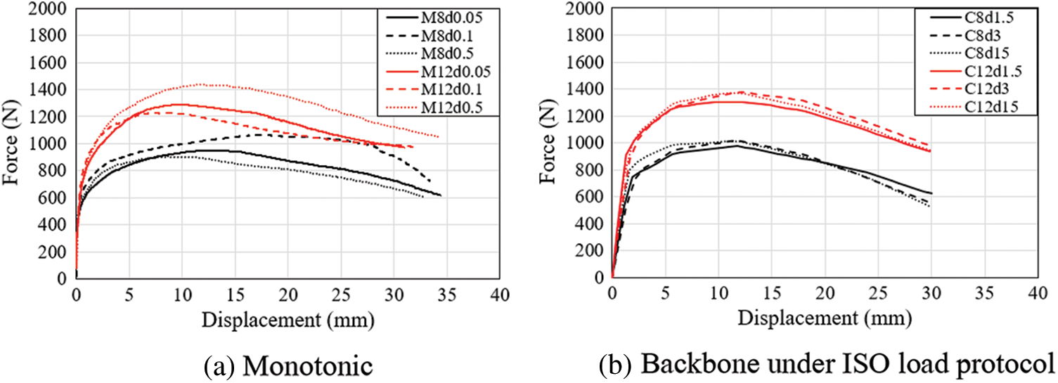
Figure 4: Load-displacement curves with different loading rates
In the case of monotonic loading tests, for both types of nail joints, the load-displacement curves under different loading rates are reasonably close to each other before the ultimate load. After reaching the ultimate load, however, deviations between the curves are observed. For reversed-cyclic loading tests shown in Fig. 4b, the loading rate has minimal influence on the backbone curves of nail joints under ISO loading protocol tests. The curves with the same nail joint details are considerably close to each other.
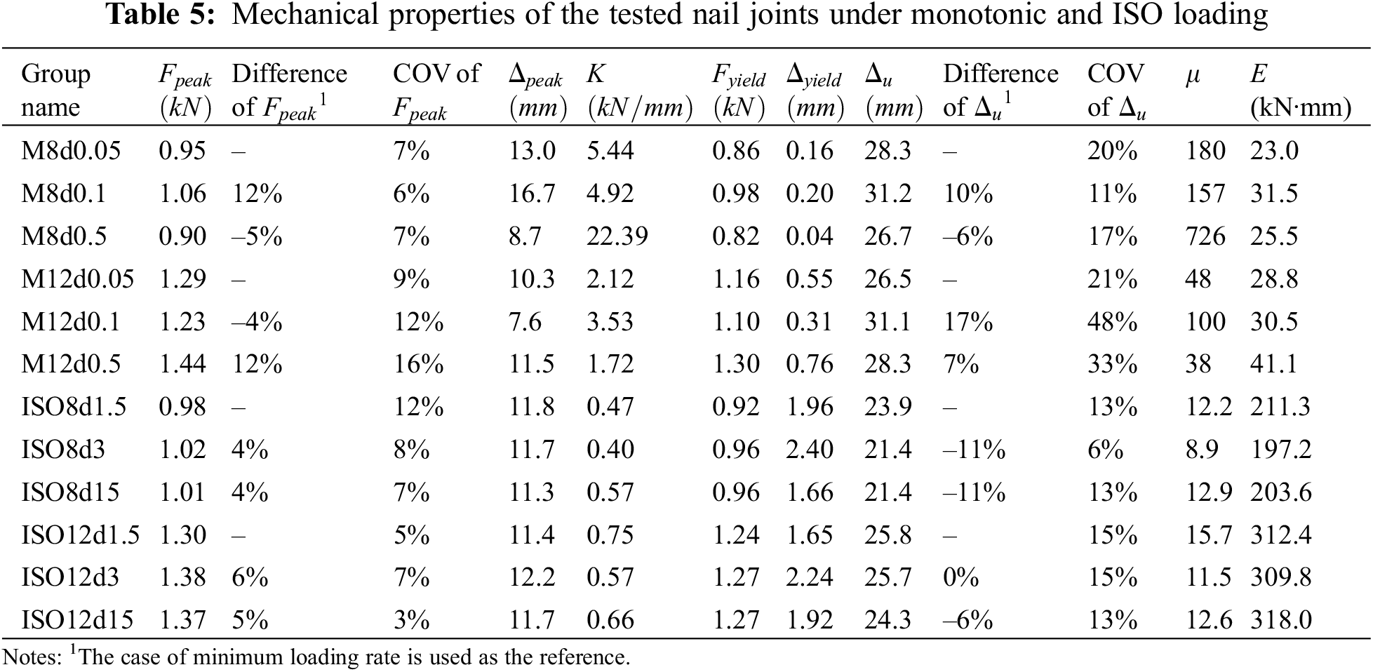
Table 5 presents the average mechanical properties, obtained from EEEP curves introduced in ASTM E2126 [12] of nail joints under the monotonic and reversed-cyclic (ISO) loading tests. In the table,
3.3 Effect of Loading Protocols
In this phase, nail joints were tested under three loading protocols with a constant loading rate of 1.5 mm/s that failed a specimen in around 10 to 30 min. Fig. 5 illustrates the hysteresis loops of nail joints under ISO, CUREE, and SPD loading protocols.
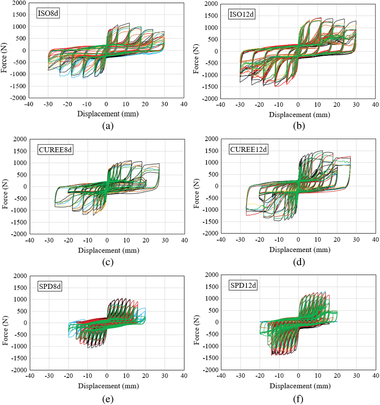
Figure 5: Load-displacement curves under different loading protocols: (a) 8d nail joints under ISO, (b) 12d nail joints under ISO, (c) 8d nail joints under CUREE, (d) 12d nail joints under CUREE, (e) 8d nail joints under SPD, and (f) 12d nail joints under SPD
The positive and negative backbone curves of each specimen were averaged first according to ASTM E2126 [12], then the backbone curves of six replicates were averaged to get the load-displacement curve for each group (Table 4). Fig. 6 shows the averaged backbone curves of nail joints under ISO, CUREE, SPD, and monotonic loading protocols. As mentioned earlier, nail breakage occurred in all SPD loading protocol tests. This results in a much smaller ultimate displacement and relatively smaller resistance of nail joints under the SPD loading protocol. Breakage due to nail fatigue under SPD loading protocol happened at an earlier stage of 8d nail joints compared with 12d nail joints (i.e., the corresponding ultimate deformation was smaller for 8d nail joints). The backbone curves under ISO and CUREE loading protocols agree well with the monotonic curve except relatively lower initial stiffness.
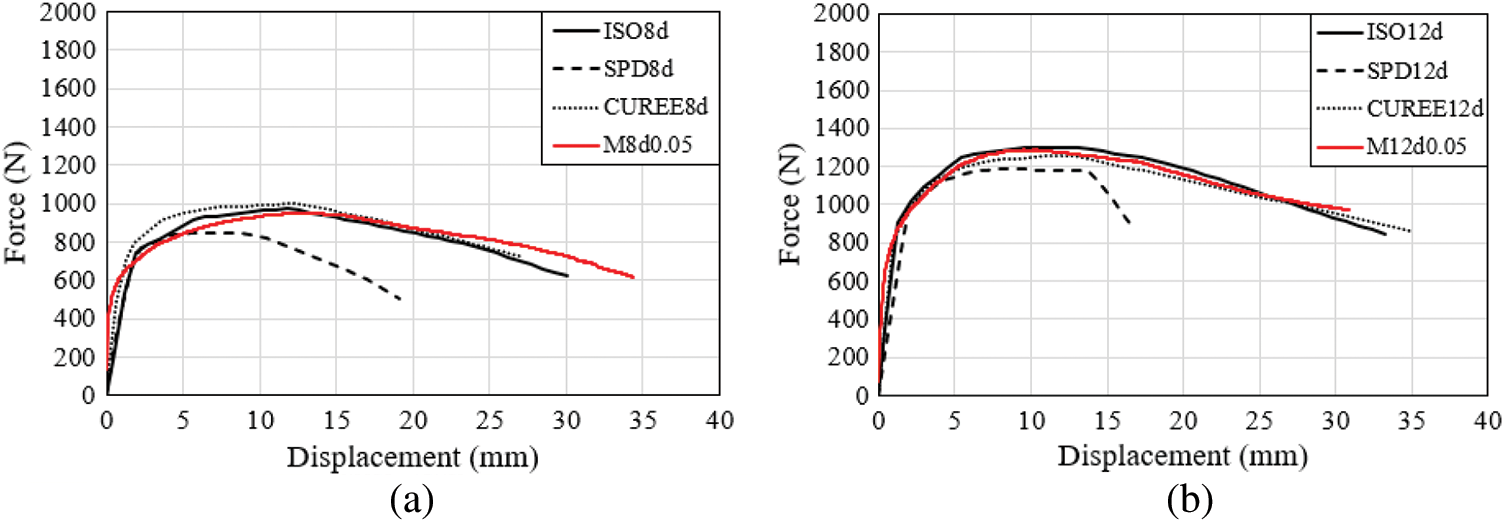
Figure 6: Backbone curves of nail joints under cyclic loads: (a) 8d nail joints, and (b) 12d nail joints
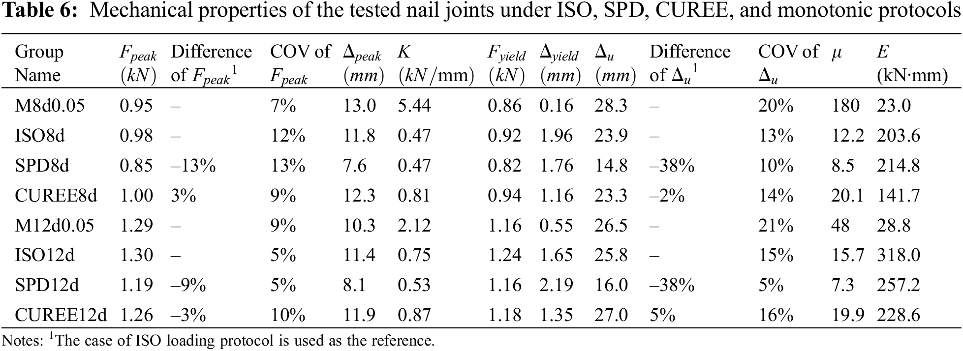
Table 6 shows the mechanical properties of nail joints for ISO, SPD, CUREE and monotonic loading protocols. The mechanical properties of the other groups are compared to that of the corresponding ISO group. From Table 6, it is found that the difference in ultimate load due to different load protocols is within 13%. Results show that the ultimate resistance of nail joints under CUREE loading protocol is similar to that under ISO protocol (± 3% difference), while the ultimate resistance under SPD loading protocol is around 10% lower than that under ISO loading protocol. This may be due to a relatively larger number of cycles included in each primary displacement increment in SPD protocol (7 cycles) compared to the other two protocols (3 cycles). Similarly, for both 8d and 12d nail joints, the displacement at the ultimate load,
Stiffness degradation is an important criterion that represents the changes in the stiffness and strength of the system while undergoing cyclic loading. In this study, the effective stiffness was used to demonstrate the stiffness degradation of the nail joints when they were experiencing different loading protocols. Effective stiffness is the slope of the line passing through the maximum positive displacement point and maximum negative displacement point in a full cycle of loading on the hysteresis loop [20]. Therefore, different loading protocols lead to different degradation patterns based on the number of repeated cycles in each step and the increment of displacement between steps. Fig. 7 shows the averaged effective stiffness degradation of nail joins under the three loading protocols. The step number of the loading protocols refers to the steps named in ASTM E2126 [12]. Each step includes several repeated cycles (shown on the horizontal axis). It can be seen that for all three loading protocols, 12d nail joint groups have higher effective stiffness compared to 8d groups. Stiffness degradation is observed under all three loading protocols when the same or reduced displacement is repeated. This stiffness degradation is due to the cumulated damage occurred in previous cycles. Under SPD loading protocol, the stiffness slightly increases in cycle 5. This is because the cycles of 2–4 have a reduced displacement compared to cycles 1 and 5–7.
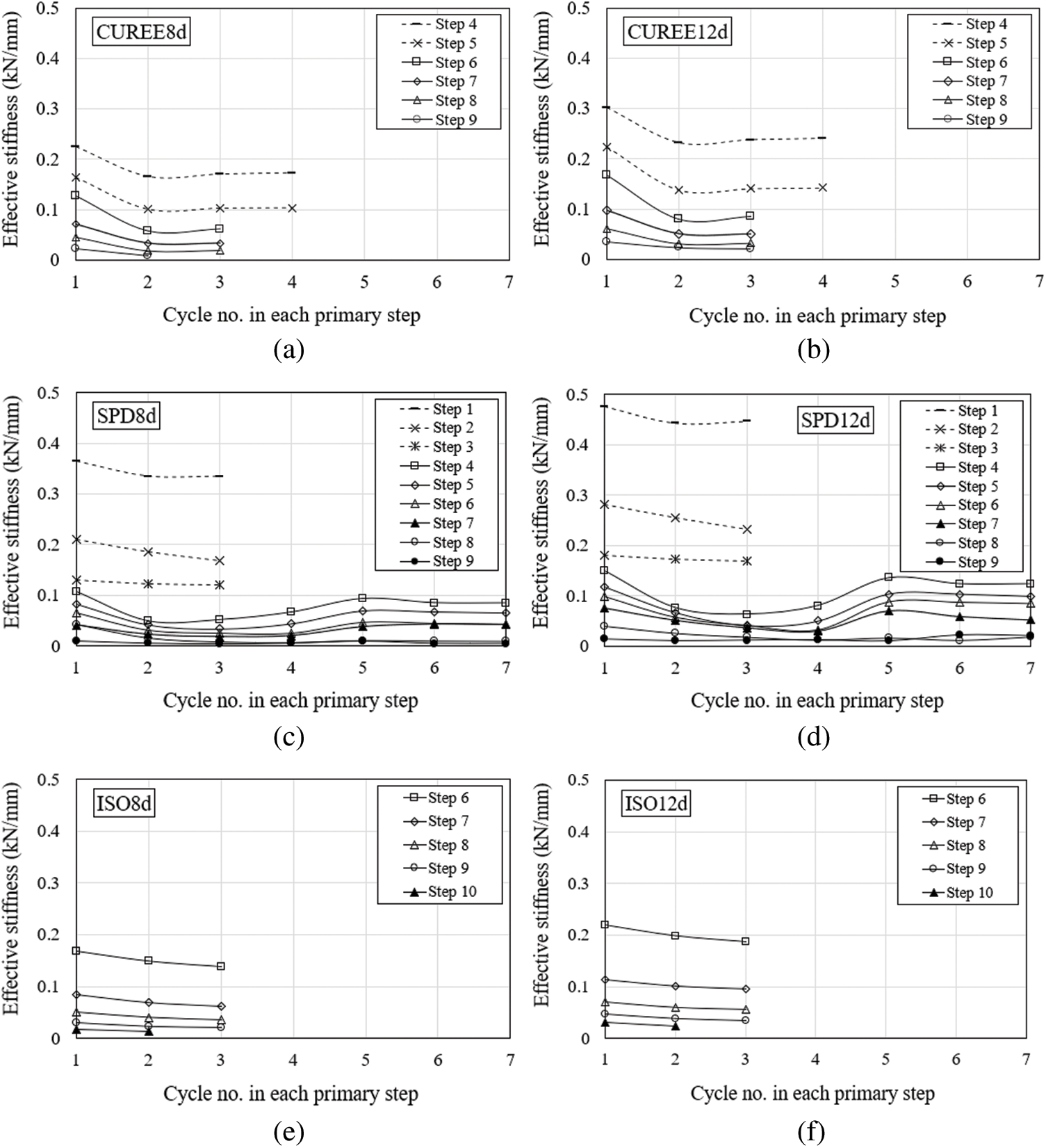
Figure 7: Effective stiffness degradation: (a) 8d nail joints under CUREE, (b) 12d nail joints under CUREE, (c) 8d nail joints under SPD, (d) 12d nail joints under SPD, (e) 8d nail joints under ISO, (f) 12d nail joints under ISO
This research investigated the effect of loading rate and loading protocol on the mechanical properties of nail joints. The results revealed that there were no discernible trends between the loading rate and the mechanical properties of nail joints within the range of loading rates investigated in this project. Generally, the variance of mechanical properties caused by different loading rates is more obvious under monotonic load than that under reversed cyclic load. In terms of loading protocols, the results showed that for both 8d and 12d nail joints, the mechanical properties under the CUREE loading protocol are similar to that under the ISO loading protocol. Both 8d and 12d nail joints experienced the lowest peak load, ultimate displacement and ductility under SPD loading protocol. This is mainly due to the fact that SPD protocol has repeated 7 cycles for each primary displacement increment, therefore has the highest cumulative damage compared to CUREE and ISO loading protocols, both of which have only repeated 3 cycles. Nail joints under CUREE loading protocol dissipated the least energy within the three cyclic protocols. It is worth noting that due to the difference between the standardized loading protocols and a real earthquake load, the properties derived under the standardized loading protocols may not be representative of those under a real earthquake event, especially for the values of ultimate displacement and the ductility.
Funding Statement: This work was funded by the Natural Sciences and Engineering Research Council of Canada, Discovery Grants RGPIN-2018-05104, LZ, https://www.nserc-crsng.gc.ca/index_eng.asp.
Conflicts of Interest: The authors declare that they have no conflicts of interest to report regarding the present study.
1. Rosowsky, D. V., Reinhold, T. A. (1999). Rate-of-load and duration-of-load effects for wood fasteners. Journal of Structural Engineering, 125(7), 719–724. DOI 10.1061/(ASCE)0733-9445(1999)125:7(719). [Google Scholar] [CrossRef]
2. Dorn, M., de Borst, K., Eberhardsteiner, J. (2013). Experiments on dowel-type timber connections. Engineering Structures, 47(2), 67–80. DOI 10.1016/j.engstruct.2012.09.010. [Google Scholar] [CrossRef]
3. Girhammar, U. A., Andersson, H. (1988). Effect of loading rate on nailed timber joint capacity. Journal of Structural Engineering, 114(11), 2439–2456. DOI 10.1061/(ASCE)0733-9445(1988)114:11(2439). [Google Scholar] [CrossRef]
4. Dolan, J. D., Madsen, B. (1992). Monotonic and cyclic nail connection tests. Canadian Journal of Civil Engineering, 19(1), 97–104. DOI 10.1139/l92-010. [Google Scholar] [CrossRef]
5. Foschi, R. O. (1982). Load/slip results for nailed connections using waferboard panels (Supplementary report A). Report to the Canadian Waferboard Association. Forintek Canada Corp., Vancouver, BC, Canada. [Google Scholar]
6. Chui, Y. H., Ni, C. (1997). Load-embedment response of timber to reversed cyclic load. Wood and Fiber Science, 29(2), 148–160. [Google Scholar]
7. Soltis, L., Mtenga, P. (1985). Strength of nailed wood joints subjected to dynamic load. Forest Products Journal, 35(11/12), 14–18. [Google Scholar]
8. BSI (1991). BC EN 26891: Timber structures-joints made with mechanical fasteners-general principles for the determination of strength and deformation characteristics. London, UK: British Standards Institution. [Google Scholar]
9. BSI (2001). BS EN 12512: Timber structures-test methods-cyclic testing of joints made with mechanical fasteners. London, UK: British Standards Institution. [Google Scholar]
10. ISO (2003). Timber structures—Joints made with mechanical fasteners—Quasi-static reversed-cyclic test method. ISO 16670. [Google Scholar]
11. ASTM (2020). ASTM D1761: Standard test methods for mechanical fasteners in wood. ASTM Int’l. PA, USA. [Google Scholar]
12. ASTM (2019). ASTM E2126: Standard test methods for cyclic (reversed) load test for shear resistance of vertical elements of the lateral force resisting systems for buildings. ASTM Int’l. PA, USA. [Google Scholar]
13. Ficcadenti, S., Steiner, M., Pardoen, G., Kazanjy, R. (1998). Cyclic load testing of wood-framed, plywood sheathed shear walls using ASTM E 564 and three loading sequences. Proceedings of 6th US National Conference on Earthquake EngineeringSeattle, Washington, USA. [Google Scholar]
14. He, M., Lam, F., Prion, H. G. (1998). Influence of cyclic test protocols on performance of wood-based shear walls. Canadian Journal of Civil Engineering, 25(3), 539–550. DOI 10.1139/l97-114. [Google Scholar] [CrossRef]
15. Karacabeyli, E., Ceccotti, A. (1998). Nailed wood-frame shear walls for seismic loads: Test results and design considerations. Atti del Structural Engineers World Congress. San Francisco, CA, USA. [Google Scholar]
16. Gatto, K., Uang, C. M. (2003). Effects of loading protocol on the cyclic response of woodframe shearwalls. Journal of Structural Engineering, 129(10), 1384–1393. DOI 10.1061/(ASCE)0733-9445(2003)129:10(1384). [Google Scholar] [CrossRef]
17. Mergos, P. E., Beyer, K. (2014). Loading protocols for European regions of low to moderate seismicity. Bulletin of Earthquake Engineering, 12(6), 2507–2530. DOI 10.1007/s10518-014-9603-3. [Google Scholar] [CrossRef]
18. Cowled, C. J. L., Crews, K., Gover, D. (2021). Influence of loading protocol on the structural performance of timber-framed shear walls. Construction and Building Materials, 288(1), 123103. DOI 10.1016/j.conbuildmat.2021.123103. [Google Scholar] [CrossRef]
19. Derakshan, S. S., Zhou, L., Ni, C. (2019). Effect of loading speed on the mechanical properties of nail joints. Modular and Offsite Construction (MOC) Summit Proceedings, pp. 462–470. Banff, Alberta, Canada. [Google Scholar]
20. Shenton III, H. W., Dinehart, D. W., Elliott, T. E. (1998). Stiffness and energy degradation of wood frame shear walls. Canadian Journal of Civil Engineering, 25(3), 412–423. DOI 10.1139/l97-108. [Google Scholar] [CrossRef]
 | This work is licensed under a Creative Commons Attribution 4.0 International License, which permits unrestricted use, distribution, and reproduction in any medium, provided the original work is properly cited. |