| Journal of Renewable Materials |
DOI: 10.32604/jrm.2022.022326
ARTICLE
Bending, Compression and Bonding Performance of Cross-Laminated Timber (CLT) Made from Malaysian Fast-Growing Timbers
1Institute for Infrastructure Engineering and Sustainable Management (IIESM), Universiti Teknologi MARA, Shah Alam, 40450, Malaysia
2School of Civil Engineering, College of Engineering, Universiti Teknologi MARA, Shah Alam, 40450, Malaysia
3Sapulut Forest Development Sdn. Bhd., Kota Kinabalu, 88400, Malaysia
4Institute of Tropical Forestry and Forest Products (INTROP), Universiti Putra Malaysia UPM, Serdang, 43400, Malaysia
*Corresponding Author: Norshariza Mohamad Bhkari. Email: nshariza@uitm.edu.my
Received: 04 March 2022; Accepted: 04 May 2022
Abstract: This study investigated the bending, compression as well as the bonding performance of CLT panels made from fast-growing timber species, i.e., Laran (Neolamarckia cadamba) and Batai (Paraserianthes falcataria). The variables studied were timber species (Laran and Batai), layers of lamination (3-layer and 5-layer), loading direction in bending (in-plane and out-of-plane), loading direction in compression (x-, y-, and z-axis) and different treatment conditions for bonding performance test. The desired outputs of this study were bending and compression properties (strength and stiffness) as well as bonding performance (block shear strength, wood failure percentage and delamination value). The bending and compression test were conducted according to EN16351:2015 and EN408:2012, respectively. On the other hand, the bonding performance test was determined by block shear and delamination test based on EN16351:2015 and EN14374:2004, respectively. Prior to block shear test, the samples were subjected to three different treatment conditions. The results showed that CLT made from 3-layer Laran timber, loaded at out-of-plane direction exhibited the highest bending properties. Contrarily, CLT made from 5-layered Batai timber, loaded at in-plane direction showed the lowest bending properties. Laran samples for compression loaded at x-axis exhibited the best compressive properties. Generally, Laran CLT showed greater bonding performance determined by shear test compared to Batai CLT for both 3- and 5-layer panels. On the contrary, delamination results showed that Batai CLT demonstrated better bonding performance compared to Laran CLT. In terms of bonding performance measured by wood failure percentage (WFP), most samples under various treatment conditions showed WFP ≥ 80% except for samples under wet condition with WFP ≤ 60%.
Keywords: Cross-laminated timber; plantation timber; flexural performance; bonding performance
Mass timber construction is gaining popularity around the world because of its potential to revolutionise the construction industry by addressing the need for green and sustainable building materials. Cross laminated timber (CLT) is a mass timber product composed of an odd number of layers (3, 5, 7, etc.) of timber boards laid side by side and laminated orthogonally with structural adhesives. CLT was developed in Austria in the 1990s and then spread to other European countries in the 2000s as a residential, office, and school building construction material [1]. CLT is an excellent material choice for the building industry due to its high strength-to-weight ratio, which allows it to support a substantial load while weighing less. CLT buildings effectively store significant amounts of carbon and have been shown to produce lower emissions than concrete or steel construction. The CLT’s prefabricated design allows for efficient construction with minimal disruption to the site’s environment. Previous research has demonstrated that CLT can compete with, and even outperform, many traditional materials [2]. CLT panels are commonly used as load bearing walls, roofs, and slabs. CLT panels are efficient and suitable for medium and high-rise timber building construction [3].
Malaysia’s natural timber log supply is decreasing [4], prompting the government to consider forest plantation as an alternative source of natural forest timber]. The rapid growth of plantation timber ensures a continuous supply chain as well as sustainable forestry. Plantation timber species in the tropics can grow four times faster than those in temperate climates, according to Okuda et al. [5], due to year-round sunlight. The Malaysian Ministry of Plantation Industries and Commodities (MPIC) has proposed planting nine species as part of its current forest plantation programme, including Laran (Neolamarckia cadamba), also known as Kelempayan in Peninsular Malaysia, and Batai (Paraserianthes falcataria) [6]. According to MS544:Part 2:2017 [7], these species are classified as tropical light hardwood. These two species are currently planted in the states of Pahang, Perak, Kelantan, Sabah, and Sarawak. Due to their low strength properties, these species are commonly used for non-structural components such as plywood, particleboard, cement-bonded board, hardboard, timber furniture, and so on, according to Nordahlia et al. [8]. However, as CLT manufacturing technology advances, the strength properties of these species can be improved, giving them a high potential for commercialization as structural components.
There are only a few scientific papers on the performance of CLT made from fast-growing species, specifically tropical hardwood species [9–15]. Corpataux et al. [12] evaluated and compared CLT made from Sengon (Falcataria moluccana), Red Jabon (Anthocephalus macrophyllus), and Acacia hybrid (Acacia mangium and Acacia auriculiformis) from Indonesia to Norway spruce (Pinus abies) sourced from Latvia as targeted strength classes of CL24 [16]. Using 1C-PUR adhesive, all CLT panels were manufactured in three layers in accordance with EN16351:2015 [17]. Bending performance was evaluated both inside and outside of the CLT plane. All CLT samples (mono-and mixed-species) had modulus of rupture (MOR) values greater than 30 N/mm2 and exceeded the CL24 targeted strength classes. In terms of bending stiffness, Sengon mono-species CLT had the lowest bending stiffness, followed by Red Jabon. When compared to Norway spruce, the bending stiffness value for these two species did not meet the CL24 target [16]. However, the researchers concluded that combining A. mangium as the outer layer can improve the strength of these mono-fast-growing species CLT.
Mohd Yusof et al. [13] investigated the physical and mechanical properties of 3-layer A. mangium CLT. The CLT was made with two different structural adhesives, PRF and PUR. CLT bonded with PRF adhesive demonstrated superior physical properties to CLT bonded with PUR adhesive in terms of water absorption (WA), thickness swelling (TS), and delamination. PUR was less water resistant, as evidenced by its higher WA and TS. Furthermore, when it came to mechanical properties, the bending strength and stiffness of CLT bonded with PRF adhesive were higher than those of the panel bonded with PUR. Other studies conducted by various researchers demonstrated that manufacturing CLT from fast-growing species increased the strength for structural applications [9–11].
CLT panel bending properties are closely related to the bonding performance of their glue lines. Only a few studies on the bonding performance of fast-growing species have been published to date [5,18,19]. Various standard testing procedures for determining bonding performance between laminations have been established based on the determination of local shear strength and wood failure percentage (WFP) in accordance with standards such as EN302:2013, EN392:1995, ASTM D 905:2013 and EN16351:2015 [20]. The bonding integrity assessment tests suggested by CLT standards, on the other hand, were designed for glulam, but experts discovered that the testing criteria are too stringent for CLT [18], focusing on softwood and temperate hardwood.
According to EN16351:2015 [17], the requirement value for bonding integrity is based on the characteristic shear strength, which must be ≥1.25 N/mm2, with each glue line having a shear strength of at least 1 N/mm2. WFP for the bonding strength of glue lines between crosswise bonded layers, on the other hand, is not mentioned in this standard. As a result, the requirement value for WFP in this study was based on EN14374:2004 [21], which stated that the average of WFP must be 70%. The total delamination length for a delamination test must not exceed 10% of the sum of all glue lines, and the maximum delamination length must not exceed 40% of the total length of a single glue line [17]. Each glue line must be split for WFP evaluation if the delamination length exceeds the required value or the surface quality of the end grain is insufficient to estimate. WFP is considered acceptable when the percentage of each split glued area is greater than 50% and greater than 70% for the total split glued area.
Yusoh et al. [19] investigated the bonding performance of four tropical fast-growing timbers, Batai (P. falcataria), Rubberwood (Hevea brasiliensis), Sesendok (Endospermum malaccensis), and Kedondong (Canarium sp.), for glue spreads ranging from 200 to 300 g/m2 and clamping pressures ranging from 0.7 to 1.4 N/mm2. The dry shear bond strength and WFP determined for this study, as well as the delamination behaviour, exceeded the minimum required values specified in EN16351:2015 [17]. This study discovered that the glue spread rate had a significant influence on shear bond strength and WFP and suggested that 200 g/m2 was sufficient. For delamination value, both parameters were not significant. Adnan et al. [18] discovered that the bonding performance of CLT was not only highly dependent on glue spread rate but also on timber species due to different wood anatomy resulting in different amounts of glue penetration. Okuda et al. [5] investigated the bonding performance of Red Jabon, Sengon, Acacia hybrid, and laminated bamboo (Dendrocalamus asper) using a delamination test. The authors discovered that CLT bonded with IC-PUR adhesive met the requirements of EN16351:2015 [17], but not EPI adhesive.
Previous research found that CLT panels made from tropical fast-growing species had promising structural performance. As a result, this paper focuses on the bending, compression, and bonding properties of CLT panels made from two locally grown fast-growing species from Sabah, Malaysia: White Laran (N. cadamba) and Batai (P. falcataria). These species were chosen for their commercial viability as CLT products. PRF adhesive was used as a binder in the fabrication of 3- and 5-layer CLT. The primary goal of this research was to determine the strength and stiffness of CLT samples subjected to bending and compression loads in different loading directions. Furthermore, through block shear and delamination tests, this study aimed to evaluate the bonding performance of this CLT product under different treatment conditions, which had not been addressed by previous research.
2.1 Manufacturing of CLT Panels
A solid sawn lamella from fast-growing species namely White Laran (N. cadamba) and Batai (P. falcataria) were selected and obtained from plantation forest in Sabah. These timbers with an average moisture content of 19% were then cut into the dimension of 30 mm thick × 115 mm width × 1500 mm length for vertical and horizontal lamella. The lamellae were then further dried to the targeted moisture content of 12% to 14%. Prior to fabrication, the lamellae were visually graded according to HS grade, MS1714:2003 [22] by certified graders. In order to obtain longer-length lamella, the lamella was finger jointed and glued using phenol-resorcinol formaldehyde (PRF) with adequate pressure. After that, the lamellas were planed and glued edge to edge by applying single glue line with PRF adhesive at the spread rate of more than 300 g/m2 using a roller-coater. The lamellas were then clamped for 4 h and the surface was planed again in order to removed excess glue. The surface glue was applied for each CLT layer and laminated orthogonally in three or five layers. The panel was then clamped using hydraulic pressure machine at 1.0 to 1.4 N/mm2 pressure for 4 h and conditioned at 20°C with relative humidity of 65%.
The CLT panels were manufactured in accordance with EN16351:2015 [17] at a CLT factory in Sabah. Five panels for each of the 3- and 5-layer CLT for every selected species with a dimension of 4 m × 1 m were produced using PRF adhesive. A glue to hardener ratio for this product is 100:25.
2.2 Determination of Moisture Content and Density
The moisture content of the test samples was determined using oven dry method according to EN13183-1:2002 [23]. The density for test samples was determined from 50 mm thick sections (thickness measured parallel to grain). The correction for density at 12% timber moisture content was carried out according to EN384:2018 [24].
2.3 Determination of Bending Strength and Stiffness
Bending strength and stiffness for major strength direction of 3- and 5-layer CLT panels under in-plane and out-of-plane loading were conducted according to EN16351:2015 [17] and EN408:2012 [25]. The bending strength, global modulus of elasticity (MOE) and local MOE was calculated using Eqs. (1)–(3), respectively, as following:
where F = load at a given point on the load deflection curve (in N);
where
where
Table 1 presents the dimension and geometrical characteristics of CLT bending test samples.

2.3.1 Bending Test with Out-of-Plane Loads
The bending test of beams with out-of-plane loads were carried out in 4-point bending according to EN16351:2015 [17]. The support distance was 24 times the test sample height and the distance between support and load was 9 times to the test sample height. The distance between the load introduced and the length of the constant moment area was 6 times to the height of the test sample. For determination of the global MOE, the deflection was measured at mid-span of beam using displacement sensor of LVDT based on the electrical resistance principle. For determination of the local MOE in bending, the deflection was measured in the neutral axis of the sample over a central length of 5 times of the test sample height. The bending test was performed using a hydraulic universal testing machine (UTM) with maximum capacity of 250 kN (AUTOMAX-T, CONTROLS, Milan, Italy) at a constant rate of displacement in which the maximum load (Fmax) was reached within 300 ± 120 s. Fig. 1 shows the setup of the CLT bending test for samples loaded at out-of-plane direction.

Figure 1: Setup for bending test with out-of-plane loads accordance with EN16351:2015 [17]
2.3.2 Bending Test with In-Plane Loads
The 4-point bending test for samples loaded at in-plane direction was setup in accordance with EN16351:2015 [17] as showed in Fig. 2. The support distance was 18 times the test sample height and the distance between support and load was one-third of the support span. The other test configuration was similar to bending test with out-of-plane load.

Figure 2: Setup for bending test with in-plane loads in accordance with EN16351:2015 [17]
2.4 Determination of Compression Properties
Table 2 summarizes important characteristics of the industrially manufactured test samples and the test configuration. The compression test was carried out according to EN408:2012 [25]. The test was performed using UTM with load cell capacity of 450 kN (AUTOMAX-T, CONTROLS, Milan, Italy) and tested in three different direction which a x, y and z-axis for 3-layer CLT and only z-axis for 5-layer CLT due to limitation of machine load capacity.

Fig. 3 shows the test scheme complying with EN408:2012 [25]. The test sample was placed on steel plate and loaded at a constant rate. For determination of compression modulus of elasticity in x-axis and y-axis, the deflection was measured using LVDT placed on both wide side of the respective test specimen with central gauge length of four times the smallest cross-sectional dimension of the specimen. For both 3- and 5-layer samples in z-axis the samples were tested in full-area cross sectional compression.

Figure 3: Test setup for CLT compression test in (a) x-axis; (b) y-axis; and (c) z-axis in accordance with EN408:2012 [25]
The compressive strength and also compressive modulus of the individual test piece were calculated using the following equations:
where Fmax = maximum load (in N); A = cross-sectional area (in mm2).
where F2 − F1 = is an increment of loads on the straight-line portion of the load deformation curve (in N); W2 − W1 = is the increment of deformation corresponding to F2 − F1 (in mm); l1= gauge length for the determination of modulus of elasticity (in mm); A = cross-sectional area (in mm2).
2.5 Determination of Bonding Performance
2.5.1 Treatment Conditions of Block Shear Samples
All block shear samples were subjected to three treatment conditions prior to block shear test. All block shear samples were prepared in the dimensions of (40 × 40 × 90) mm and (40 × 40 × 150) mm for 3- and 5-layer CLT panel, respectively. The treatment conditions for all test samples are given in Table 3.

The test was conducted using Universal Testing Machine (UTM) of 450 kN (AUTOMAX-T, CONTROLS, Milan, Italy). The test samples were prepared according to EN16351:2015 [17] and cut at various random location to represent bonding performance of the entire CLT panel. The sample was then placed in the shearing tool and the glue lines was loaded by self-adjusting bearing in the direction of the end-grain as shown in Fig. 4. For 3-layer test samples, both bond lines were tested for block shear. Meanwhile, for 5-layer samples, all four bond lines were tested. The failure was targeted to occur not less than 20 s with a constant loading rate.
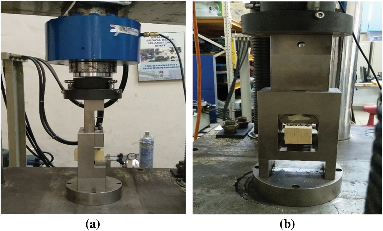
Figure 4: Test set up for CLT block shear test: (a) front view; (b) side view
The wood failure of every tested glue line was expressed in percentage to the nearest 5%. Meanwhile, the shear strength was then determined using Eq. (6).
where
The delamination test was performed according to EN16351:2015 [17]. The test samples were prepared with the dimensions of (100 × 100 × 90) mm and (100 × 100 × 150) mm for 3- and 5-layer CLT, respectively. The test samples were selected in random locations of CLT panel in such a way that represent the production run. For each species, a total of 60 test samples were prepared for each 3- and 5-layer CLT. The total length of glue lines on the end-grain surfaces of the test specimen was measured.
The test samples were subjected to the test cycle described in Annex C, EN16351:2015 [17]. The test samples were placed and completely submerged into water in the pressure vessel (Fig. 5a). The test pieces were separated so that all the end grains were freely exposed to water (Fig. 5b). The test samples in the pressure vessel were subjected to vacuum of at least 85 kPa for 30 min. Then the vacuum was released and a pressure of at least 600 kPa was applied to the test pieces for 2 h.
Test samples were then dried in an oven up to 75°C for approximately 15 h as shown in Fig. 5c. Delamination was measured when the mass of the test samples has returned to within 100% to 110% from the original mass (Fig. 5d). The length of opened joint was measured along the glue-lines accordance with the criteria stated in EN16351:2015 [17].

Figure 5: Test set up for CLT delamination test: (a) pressure vessel; (b) CLT samples spaced and separated before submerged in the pressure vessel; (c) drying of samples in an oven; (d) measurement of the delamination length
3.1 Bending Strength and Stiffness for In-Plane and Out-Plane Loading Direction
The summary of bending strength and stiffness for in-plane and out-of-plane loading direction is shown in Table 4. It can be observed that, the strength and stiffness for Laran CLT was generally slightly higher compared than that of Batai CLT especially for 5-layer CLT. This was due to the fact that Laran has higher density than Batai. The results were consistent with the findings by Adnan et al. [18] which showed that CLT made from higher density timber demonstrated higher bending performance. However, for in-plane samples, the MOR for 3-layer Batai CLT (16.66 N/mm2) was slightly higher than that of 3-layer Laran CLT (15.78 N/mm2). Contrarily, the MOE of 3-layer Laran CLT (7662 N/mm2) was much higher than that of 5-layer Batai CLT (6038 N/mm2). Similar trend can also be observed in out-of-plane samples.

The MOR values for samples loaded at of out-of-plane direction showed higher value compared than that of MOR values for in-plane loading direction for both species in 3- and 5-layer CLT. For in-plane load direction, the bending strength of 3-layer CLT from both species showed higher value compared to 5-layer CLT with percentage difference of 16% and 36% for Laran and Batai, respectively. These results indicated that the increase in the number of layers contributed to the decrease in bending strength. Similar trend was also reported in other studies [26–29]. He et al. [26] stated that the bending strength decreases with increasing panel thickness while maintaining the same span-to-depth ratio. Also, increasing the panel’s thickness will only slightly increase the max load but not the overall bending strength of a panel. It is because bending strength of a panel is mainly governed by the strength of the outermost lamination.
For samples loaded at out-of-plane direction, similar trend was also observed, where the percentage difference is 10% and 20% for Laran and Batai, respectively. The strength difference between 3- and 5-layer CLT panels could be attributed to the manufacturing process of the CLT panels, and additional investigation is required. It was hypothesised that the duration and pressure applied for 5-layer CLT were insufficient, and that the effect was more significant when CLT samples were loaded at in-plane direction.
The local and global MOE for all the samples was measured and determined using Eqs. (2) and (3). MOEglobal (Em,g) provides the measurement of total deflection representative of the whole span which combines with bending and shear deformation [30]. It can be observed that CLT samples subjected to out-of-plane loading showed higher global and local MOE value for 3- and 5-layer CLT for both timber species. This result was consistent with those reported by Li et al. [31]. For in-plane samples, Em,g of 3-layer Laran CLT was 18% higher than the 5-layer counterpart. Meanwhile, 3-layer Batai CLT showed only 7% higher Em,g than the 5-layer counterpart. For out-of-plane loading direction, the Em,g of 3-layer Laran CLT was only 4% higher than compared to 5-layer CLT of the same species. However, for Batai CLT, the Em,g exhibited a reduction by 22% when the number of layers was increased from 3 layers to 5 layers.
The MOElocal (Em,l) which measured at the mid-span was used to determine the pure bending deflection without shear effect. In this study, the Em,l for out-plane load direction for 5-layer Laran CLT was taken from one test sample only since result for the other test samples were not acceptable due to problem in LVDT measurement during testing. Nocetti et al. [32] stated that in the measurement of local displacement, higher risks of measurement errors are possible due to little deflection size at the reference points. The Em,l values for 3-layer Laran samples loaded at in-plane direction was 12% higher the 5-layer samples. On the other hand, for Batai CLT, the Em,l values for 3-layer samples was 9% higher than the 5-layer sample. For out-of-plane loading samples, the Em,l for 5-layer CLT was higher compared to the 3-layer counterpart with percentage difference of 16%. Contrarily, for Batai CLT, the 3-layer samples presented 20% higher Em,l when compared to 5-layer samples.
3.2 Failure Pattern of CLT in Bending for In-Plane and Out-of-Plane Loading Direction
Failure pattern of CLT loaded at out-of-plane direction is presented in Fig. 6. All samples in 3-and 5-layer CLT exhibited similar failure pattern. Overall, the total failure occurred more slowly after first crack was observed. The failure mode of CLT Laran and Batai started at the finger joint in tension zone. Then the tearing failure propagated to the glue line and later the rolling shear failure occurred in transverse direction of the lamination. He et al. [33] also reported that most CLT samples tested at out-of-plane direction failed at the tension zone, however without glue line failure. Contrarily, most tension failure of the samples observed in this study was accompanied by glue line and rolling shear failure. This might explain the relatively low bending strength and stiffness obtained in this study. For failure pattern of in-plane loaded CLT samples, similar pattern was observed when the crack started at the finger joint and then propagated to the transverse lamination presented in Fig. 7. However, total failure of the samples tested occurred almost immediately after first crack.

Figure 6: Failure modes of Laran CLT in bending out-plane loading direction: (a) tension failure started at finger joint; (b) tearing failure propagated from failure in finger joint; and (c) rolling shear failure at middle lamination layer

Figure 7: Failure modes of Laran CLT in bending in-plane loading direction: (a) failure started at finger joint at tension zone; (b) from soffit of CLT panel, finger jointed failure extended into shear failure and propagated to another lamination
The mean compressive strength and modulus values for all the CLT samples tested are tabulated in Table 5. Laran CLT demonstrated higher compressive strength and modulus compared to Batai CLT. This trend supported the results obtained from bending test which showed that higher density Laran CLT showed better structural performance than lower density Batai CLT. Comparing the properties from 3 different axis, it was found that Laran CLT samples loaded at x-axis and z-axis has higher compressive strength and modulus than that of Batai CLT. Meanwhile, compressive strength loaded at y-axis was lower in Laran CLT when compared to Batai CLT.

3.4 Failure Pattern of CLT under Compression Load
Almost all test samples of Laran and Batai CLT in x- and y-axis failed in crushing failure due to weakness in compression and failure along maximum compression line as shown in Fig. 8. This result is in agreement with Huang et al. [34] which found that CLT sample under compression load would produce compressive crush failure on the concave side. A few specimens failed caused by shearing on the convex side is presented in Fig. 9 and splitting failure due to the low bonding integrity between wood and adhesive shown in Fig. 10. For specimens in z-axis direction tested in full area compression, almost all specimens for both species failed in crushing due to densification and cause a distortion to specimens as clearly shown in Fig. 11. The increasing of stress is faster with larger deformation because of the collapsed and densification of the fibres causes the specimen can resist a higher load.

Figure 8: Crushing failure on the concave of CLT samples at x-axis

Figure 9: Shearing failure on the convex of CLT samples at x-axis

Figure 10: Splitting failure along the glue line of CLT samples at y-axis

Figure 11: Crushing failure and densification of CLT samples in z-axis direction
3.5.1 Shear Bond Strength under Various Treatment Conditions
The mean shear strength values for all the CLT samples tested was summarised in Table 6. For CLT samples of both species, 5-layer CLT in dry condition showed the highest value (2.49 N/mm2) while 3-layer Batai CLT in wet and redry condition showed the lowest value (0.84 N/mm2). Generally, Laran CLT demonstrated better shear strength than Batai CLT when subjected to various treatment conditions with all samples surpassing the minimum shear strength requirement of 1 N/mm2 [17]. The shear strength of Laran CLT ranged from 1.39 to 2.49 N/mm2. Contrarily, the shear strength of Batai CLT ranged from 0.84 to 1.29 N/mm2. 3- and 5-layer Batai CLT failed to meet the minimum requirement of shear strength under wet and wet and redry conditions with shear strength value ranging from 0.84 to 0.99 N/mm2. This could be due to the permanent degradation of glue line under continuous influence of extreme moisture and heat [35]. Besides that, the undesirable shear strength of Batai CLT samples might be caused by the non-uniform density of the Batai timber within and between the laminations which consequently resulted in non-uniform swelling of the samples. Such swelling is difficult for the adhesive system to accommodate which can lead to the failure of wood adhesive bond [36,37]. However, further investigation should be carried out in future study to verify the effect of this factor in this study.
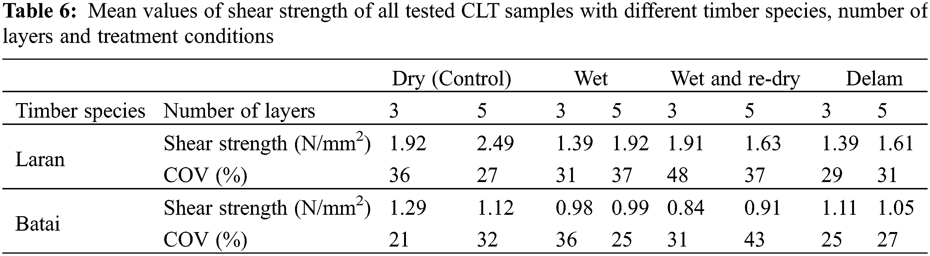
It is clearly shown in Table 6 that the shear strength values of 3- and 5-layer Laran and Batai CLT samples in dry condition are higher than the samples subjected to different treatment conditions which was expected. Three-layer Laran CLT samples under dry condition showed the highest shear strength followed by samples under wet and redry condition, wet condition and delam condition. 5-layer Laran CLT samples under dry condition showed the highest shear strength followed by samples under wet condition, wet and redry condition, and delam condition. On the other hand, 3-layer Batai CLT samples under dry condition showed the highest shear strength followed by samples under delam condition, wet condition and wet and redry condition. Five-layer Batai CLT samples under dry condition showed the highest shear strength followed by samples under delam condition, wet condition and wet and redry condition. Nonetheless, it is rather difficult to draw a conclusion on the effects of the treatment condition on the shear strength of the sample as the COV was quite high. Further research is needed to investigate the reason causing the inconsistency in shear strength for all the CLT samples tested.
3.5.2 Wood Failure Percentage under Various Treatment Conditions
Fig. 12 shows the histogram and normal distribution curve for WFP of all samples subjected to various treatment conditions. EN16351:2015 [17] clearly stated the value of WFP (100%) required if the shear strength between parallel bonded layers is <2 N/mm2. However, the WFP required for crosswise bonded layers is not given. Therefore, EN14374:2004 [18] was used in this study to evaluate the WFP of the tested CLT samples. According to EN14374:2004 [21], the average WFP must be ≥70%. The WFP for most CLT samples in wet condition were less than 70% as shown in Fig. 12b thus did not fulfil the requirement stated in the standard. Meanwhile, most dry CLT samples as well as those subjected to wet and redry, and delam condition showed good bonding strength with WFP more than 80%. Also, it was shown that after the CLT samples were subjected to heat and extreme moisture they were likely to regain some of the bonding strength after redry as shown in wet and redry samples with high WFP. It should be stressed that, the requirement value of WFP used as the reference in this study is not meant for CLT specifically as no such requirement is provided in any of the current CLT standards. This value may not be appropriate for CLT samples, particularly CLT panels fabricated from tropical hardwoods. The diffuse-porous morphological structure of tropical hardwoods may result in a different bonding performance than those of softwood and temperate hardwood CLT [38]. In addition, the penetration of adhesive into the surface of wood is significantly affected by the grain angle of the wood surface as CLT is laminated orthogonally and poor penetration of adhesive into the surface of lamination will be reflected in the WFP under excessive stress [39].

Figure 12: Histogram and normal distribution curve of wood failure percentage (WFP) for all CLT samples subjected to different treatment conditions: (a) dry samples; (b) wet samples; (c) wet and redry samples; (d) delam samples
The delamination percentage of Laran and Batai CLT with 3 and 5 layers of lamination was determined. It was found that good bonding quality of glue lines and high resistance against delamination was observed in 5-layer CLT for Laran and Batai. All test samples fulfilled the requirement of maximum laminations where the delamination length did not exceed 40% of the total length of a single glue line. However, several test samples from 3- and 5-layer CLT for Laran and Batai exceeded the total delamination length of 10% from the sum of all glue lines. 3-layer Laran CLT showed the lowest bonding strength determined by delamination test, where only 47% of the total samples met the requirement value which indicates that wood-adhesive bonding under internal stresses was inadequate. On the other hand, 5-layer Batai CLT showed excellent performance under delamination with 87% of samples fulfil the requirement stipulated in the standard.
The bending properties (MOR and MOE), compression properties as well as the bonding performance of CLT fabricated from fast-growing light hardwoods, i.e., Laran and Batai with 3 and 5 layers of lamination were studied. The conclusions of this study are the summarised as follow:
1. The bending MOR and MOE values of Laran CLT were higher compared to Batai CLT due to Laran timber having higher density.
2. In terms of bending properties based on loading direction of the CLT panel, samples loaded at out-of-plane direction performed better than those loaded at in-plane direction.
3. The bending properties of 3-layer CLT was higher compared to 5-layer CLT for both timber species when tested at major strength direction.
4. CLT samples made from Laran timber showed the highest compressive properties when loaded at x-axis, followed closely by samples loaded at y-axis. Sample loaded at z-axis showed the poorest performance.
5. For CLT samples subjected to various treatment conditions, the shear strength of most samples meet the minimum requirement of 1 N/mm2. Also, most samples showed acceptable WFP of more than 80% with the exception of samples subjected to wet condition which most samples showed WFP of 60%.
6. Batai CLT outperformed Laran CLT in terms of bonding performance due to delamination.
Acknowledgement: The author would like to thank School of Civil Engineering, College of Engineering Universiti Teknologi MARA (UiTM) and Institute for Infrastructure Engineering and Sustainable Management (IIESM) for the facilities used during the study.
Funding Statement: This research was funded by Lancar Syabas Sdn Bhd (20210202003).
Conflicts of Interest: The authors declare that they have no conflicts of interest to report regarding the present study.
1. Brandner, R., Flatscher, G., Ringhofer, A., Schickhofer, G., Thiel, A. (2016). Cross laminated timber (CLTOverview and development. European Journal of Wood and Wood Products, 74(3), 331–351. DOI 10.1007/s00107-015-0999-5. [Google Scholar] [CrossRef]
2. Espinoza, O., Trujillo, V. R., Laguarda Mallo, M. F., Buehlmann, U. (2016). Cross-laminated timber: Status and research needs in Europe. BioResources, 11(1), 281–295. DOI 10.15376/biores.11.1.281-295. [Google Scholar] [CrossRef]
3. Sun, J., Niederwestberg, J., Cheng, F., Chui, Y. (2020). Frequencies prediction of laminated timber plates using ANN approach. Journal of Renewable Materials, 8(3), 319–328. DOI 10.32604/jrm.2020.08696. [Google Scholar] [CrossRef]
4. Forestry Department of Peninsular Malaysia (2021). Forestry statistic. https://www.forestry.gov.my/. [Google Scholar]
5. Okuda, S., Corpataux, L., Muthukrishnan, S., Wei, K. H. (2018). Cross-laminated timber with renewable and fast-growing tropical species in South east Asia. 2018 World Conference onTimber Engineering, pp. 19–23. Seoul, Korea. [Google Scholar]
6. Ahmad Zuhaidi, Y., Hassan, N. H., Tong, L. N., Hong, H. L., Zorkarnain, F. A. (2020). Comparing the early growth performance of plantation-grown Eucalyptus hybrid and Eucalyptus pellita, South Johore, Peninsular Malaysia. World Journal of Advanced Research and Reviews, 6(2), 234–238. DOI 10.30574/wjarr.2020.6.2.0157. [Google Scholar] [CrossRef]
7. MS544:Part 2 (2017). Structural use of timber. Code of practice for permissible stress design, materials and workmanship. Cyberjaya, Malaysia: Department of Standards Malaysia. [Google Scholar]
8. Nordahlia, A. S., Lim, S. C., Hamdan, H., Anwar, U. M. K. (2014). Wood properties of selected plantation species: Tectona grandis (teakNeolamarckia cadamba (kelempayan/LaranOctomeles sumatrana (binuang) and Paraserianthes falcataria (batai). Timber Technology Bulletin, 54, 1–8. [Google Scholar]
9. Husain, H., Khairun, M., Uyup, A. (2016). Cross-laminated timber made from Malaysian pioneer species timber. Timber Technology Bulletin, 59, 1–6. [Google Scholar]
10. Liao, Y., Tu, D., Zhou, J., Zhou, H., Yun, H. et al. (2017). Feasibility of manufacturing cross-laminated timber using fast-grown small diameter eucalyptus lumbers. Construction and Building Materials, 132(1), 508–515. DOI 10.1016/j.conbuildmat.2016.12.027. [Google Scholar] [CrossRef]
11. Pangh, H., Hosseinabadi, H. Z., Kotlarewski, N., Moradpour, P., Lee, M. et al. (2019). Flexural performance of cross-laminated timber constructed from fibre-managed plantation eucalyptus. Construction and Building Materials, 208(6), 535–542. DOI 10.1016/j.conbuildmat.2019.03.010. [Google Scholar] [CrossRef]
12. Corpataux, L., Okuda, S., Kua, H. W. (2020). Panel and plate properties of Cross-laminated timber (CLT) with tropical fast-growing timber species in compliance with Eurocode 5. Construction and Building Materials, 261(5–6), 119672. DOI 10.1016/j.conbuildmat.2020.119672. [Google Scholar] [CrossRef]
13. Mohd Yusof, N., Md Tahir, P., Lee, S. H., Khan, M. A., Mohammad Suffian James, R. (2019). Mechanical and physical properties of Cross-Laminated Timber made from Acacia mangium wood as function of adhesive types. Journal of Wood Science, 65(1), 1–11. DOI 10.1186/s10086-019-1799-z. [Google Scholar] [CrossRef]
14. Muñoz, F., Tenorio, C., Moya, R., Navarro-Mora, A. (2022). CLT fabricated with Gmelina arborea and Tectona grandis wood from fast-growth forest plantations: Physical and mechanical properties. Journal of Renewable Materials, 10(1), 1–17. DOI 10.32604/jrm.2022.017392. [Google Scholar] [CrossRef]
15. Gui, T., Cai, S., Wang, Z., Zhou, J. (2020). Influence of aspect ratio on rolling shear properties of fast-grown small diameter eucalyptus lumber. Journal of Renewable Materials, 8(9), 1053–1066. DOI 10.32604/jrm.2020.011645. [Google Scholar] [CrossRef]
16. Schickhofer, G., Brandner, R., Bauer, H. (2016). Introduction to CLT-product properties-strength classes. Cross Laminated Timber-A Competitive Wood Product for Visionary and Fire Safe Buildings: Joint Conference of COST Actions FP1402 and FP1404, pp. 9–32. Stockholm, Sweden. [Google Scholar]
17. EN 16351 (2015). Timber structures-cross laminated timber-requirements. Brussels, Belgium: Requirements. European Committee for Standardization (CEN). [Google Scholar]
18. Adnan, N. A., Md Tahir, P., Husain, H., Lee, S. H., Anwar Uyup, M. K. et al. (2021). Effect of ACQ treatment on surface quality and bonding performance of four Malaysian hardwoods and cross laminated timber (CLT). European Journal of Wood and Wood Products, 79(2), 285–299. DOI 10.1007/s00107-020-01609-7. [Google Scholar] [CrossRef]
19. Yusoh, A. S., Tahir, P. M., Uyup, M. K. A., Lee, S. H., Husain, H. et al. (2021). Effect of wood species, clamping pressure and glue spread rate on the bonding properties of cross-laminated timber (CLT) manufactured from tropical hardwoods. Construction and Building Materials, 273(3), 121721. DOI 10.1016/j.conbuildmat.2020.121721. [Google Scholar] [CrossRef]
20. Sikora, K. S., McPolin, D. O., Harte, A. M. (2016). Shear strength and durability testing of adhesive bonds in cross-laminated timber. The Journal of Adhesion, 92(7–9), 758–777. DOI 10.1080/00218464.2015.1094391. [Google Scholar] [CrossRef]
21. EN 14374 (2004). Timber structures. Structural laminated veneer lumber. Requirements. Brussels, Belgium: European Committee for Standardization (CEN). [Google Scholar]
22. MS 1714 (2003). Specification for visual strength grading of tropical hardwood timber. Cyberjaya, Malaysia: Department of Standards Malaysia. [Google Scholar]
23. EN 13183-1 (2002). Moisture content of a piece of sawn timber–Part 1: Determination by oven dry method. Brussels, Belgium: European Committee for Standardization (CEN). [Google Scholar]
24. EN 384 (2018). Structural timber-determination of characteristic values of mechanical properties and density. Brussels, Belgium: European Committee for Standardization (CEN). [Google Scholar]
25. EN 408 (2012). Timber structures-structural timber and glued laminated timber-determination of some physical and mechanical properties. Brussels, Belgium: European Committee for Standardization (CEN). [Google Scholar]
26. He, M., Sun, X., Li, Z., Feng, W. (2020). Bending, shear, and compressive properties of three-and five-layer cross-laminated timber fabricated with black spruce. Journal of Wood Science, 66(1), 1–17. DOI 10.1186/s10086-020-01886-z. [Google Scholar] [CrossRef]
27. Boggian, F., Andreolli, M., Tomasi, R. (2019). Cross laminated timber (CLT) beams loaded in plane: Testing stiffness and shear strength. Frontiers in Built Environment, 58, 1–12. DOI 10.3389/fbuil.2019.00058. [Google Scholar] [CrossRef]
28. Choi, C., Kojima, E., Kim, K. J., Yamasaki, M., Sasaki, Y. et al. (2018). Analysis of mechanical properties of cross-laminated timber (CLT) with plywood using Korean larch. BioResources, 13(2), 2715–2726. DOI 10.15376/biores.13.2.2715-2726. [Google Scholar] [CrossRef]
29. Gong, Y., Liu, F., Tian, Z., Wu, G., Ren, H. et al. (2019). Evaluation of mechanical properties of cross-laminated timber with different lay-ups using Japanese larch. Journal of Renewable Materials, 7(10), 941–956. DOI 10.32604/jrm.2019.07354. [Google Scholar] [CrossRef]
30. Solli, K. H. (2000). Modulus of elasticity—Local or global values. Proceedings of the 6th World Conference on Timber Engineering, Whistler, Canada. [Google Scholar]
31. Li, H., Wang, L., Wei, Y., Wang, B. J., Jin, H. (2022). Bending and shear performance of cross-laminated timber and glued-laminated timber beams: A comparative investigation. Journal of Building Engineering, 45(9), 103477. DOI 10.1016/j.jobe.2021.103477. [Google Scholar] [CrossRef]
32. Nocetti, M., Brancheriau, L., Bacher, M., Brunetti, M., Crivellaro, A. (2013). Relationship between local and global modulus of elasticity in bending and its consequence on structural timber grading. European Journal of Wood and Wood Products, 71(3), 297–308. DOI 10.1007/s00107-013-0682-7. [Google Scholar] [CrossRef]
33. He, M., Sun, X., Ren, H., Li, Z., Feng, W. (2021). Experimental study on the system effect of bending cross-laminated timber fabricated with Karamatsu larch. Construction and Building Materials, 299(1), 124271. DOI 10.1016/j.conbuildmat.2021.124271. [Google Scholar] [CrossRef]
34. Huang, Z., Huang, D., Chui, Y. H., Shen, Y., Daneshvar, H. et al. (2022). Modeling of Cross-Laminated Timber (CLT) panels loaded with combined out-of-plane bending and compression. Engineering Structures, 250(2), 113335. DOI 10.1016/j.engstruct.2021.113335. [Google Scholar] [CrossRef]
35. Bockel, S., Harling, S., Grönquist, P., Niemz, P., Pichelin, F. et al. (2020). Characterization of wood-adhesive bonds in wet conditions by means of nanoindentation and tensile shear strength. European Journal of Wood and Wood Products, 78(3), 449–459. DOI 10.1007/s00107-020-01520-1. [Google Scholar] [CrossRef]
36. Frihart, C. R., Beecher, J. F. (2016). Factors that lead to failure with wood adhesive bonds. World Conference on Timber Engineering, pp. 22–25. Vienna, Austria. [Google Scholar]
37. Gong, Y., Wu, G., Ren, H. (2016). Block shear strength and delamination of cross-laminated timber fabricated with Japanese larch. BioResources, 11(4), 10240–10250. DOI 10.15376/biores.11.4.10240-10250. [Google Scholar] [CrossRef]
38. Hänsel, A., Sandak, J., Sandak, A., Mai, J., Niemz, P. (2021). Selected previous findings on the factors influencing the gluing quality of solid wood products in timber construction and possible developments: A review. Wood Material Science & Engineering, 20(11), 1–12. DOI 10.1080/17480272.2021.1925963. [Google Scholar] [CrossRef]
39. Hass, P. (2014). Penetration behaviour of adhesives into solid wood and micromechanics of the bondline (Ph.D. Thesis). ETH Zurich, Switzerland. [Google Scholar]
 | This work is licensed under a Creative Commons Attribution 4.0 International License, which permits unrestricted use, distribution, and reproduction in any medium, provided the original work is properly cited. |