| Journal of Renewable Materials |
DOI: 10.32604/jrm.2022.021840
ARTICLE
Multi-Layer and Multi-Objective Optimization Design of Supporting Structure of Large-Scale Spherical Solar Concentrator for the Space Solar Power Station
School of Chemical Engineering, Northwest University, Xi’an, 710069, China
*Corresponding Author: Lin Zhu. Email: zl@nwu.edu.cn
Received: 08 February 2022; Accepted: 21 March 2022
Abstract: Space solar power station is a novel renewable energy equipment in space to provide the earth with abundant and continuous power. The Orb-shaped Membrane Energy Gathering Array, one of the alternative construction schemes in China, is promising for collecting space sunlight with a large-scale spherical concentrator. Both the structural and optical performances such as root mean square deformation, natural frequency, system mass, and sunlight blocking rate have significant influences on the system property of the concentrator. Considering the comprehensive performance of structure and optic, this paper proposes a novel mesh grid based on normal polyhedron projection and spherical arc bisection for the supporting structure to deal with the challenge of the large-scale structural modular design. For both achieving low system mass and high surface precision, a multi-layer and multi-objective optimization model is proposed by classifying the supporting structure into different categories and optimizing their internal and external diameters. The Particle Swarm Optimization algorithm is adopted to find optimal sectional dimensions of the different kinds of supporting structure. The infinite model is also established and structural analysis is carried out, which are expected to provide a certain reference for the subsequent detailed structural design. The numerical results indicate that the spherical concentrator designed by the novel mesh grid would obtain as high as 94.37% sunlight collection efficiency. The supporting structure constructed with the multiple layers would reduce the system quality by 6.92%, sunlight blocking rate by 28.54%, maximum deformation by 41.50%, and root mean square by 9.48% to the traditional single layer, respectively.
Keywords: Solar power; space solar power station; the OMEGA concept; structural optimization; particle swarm optimization
Nomenclature
| Ab | blocking area of supporting structure (m2) |
| Ar | sunlight irradiating area (m2) |
| b, bmin | eigenfrequency and its constraint (Hz) |
| C1, C2 | cognitive and social factors |
| ej,k | power of a single sampling ray (W) |
| E | elastic modulus (GPa) |
| I0 | solar constant (W/m2) |
| m, mmax | system mass and its constraint (t) |
| m0, m1 | number of segments in longitudinal and latitudinal direction |
| M | number of subsections |
| n | unit vector along the normal |
| Nj | number of sun rays reflected in a single subsection |
| | pbest and gbest |
| Rc | radius of the ideal spherical concentrator (m) |
| Re,i | external radius of a circular beam (m) |
| Rinc | unit vector of an incident ray |
| Rref | unit vector of its reflected ray |
| | random numbers distributed uniformly on the interval [0, 1] |
| | inner and outer radius of the three categories of the pipe beams (m) |
| | velocity vector |
| | position vector |
| α | incident angle (°) |
| ηc | collection efficiency |
| ηs, ηsmax | blocking rate and its constraint (%) |
| θi, φj | elevation and azimuth angle (rad) |
| ρ | density (kg/m3) |
| μ | poisson ratio |
| ω, ω1, ω2 | weighting coefficients |
A clean and renewable energy platform can be truly established only when energy is driven by solar power. However, ground-based solar energy is small in scale and low in efficiency because it is greatly affected by climate, geography, and other factors. Space solar power station (SSPS) has demonstrated an exclusive advantage, where the power density is 1367 W/m2, much higher than that of ground-based solar energy (about 300 W/m2) [1]. A typical SSPS will consist of several subsystems, such as a solar energy collection system (SECS), a wireless power transmitting system (WPT), and a ground receiving system.
The SECS is the frontend of the SSPS, the size of which would reach km level and the performance of which would directly affect the overall performance of the SSPS. The conceptual design of the SECS is greatly important and several classical schemes have been proposed until now. Classical schemes can be classified by focus mode into three types, such as non-focusing mode, point-focusing mode, and distribution-focusing mode.
The original SSPS, the reference model, and the tethered SSPS capture sunlight by the non-focusing mode [2–4]. These schemes have the advantage of simple and scalable structure, but the planar photovoltaic array is too large, the light collection rate fluctuates greatly, and the system efficiency is low.
Focusing technology can decrease the area of the cell array whilst increasing the photovoltaic conversion efficiency. The Integrated Symmetrical Concentrator (ISC) utilizes parabolic point-focusing mode but complicated control strategies and thermal problems on the sandwich structure restrict its realization [5]. The ALPHA (Arbitrarily Large Phased Array) collects sunlight by separately adjusting 4,662 groups of reflectors to focus sunlight [6,7]. Complicated control strategy, self-shadowing, and light leaking decrease the energy collection efficiency.
To improve the performance presented above, the Chinese research team proposed the OMEGA (Orb-shaped Membrane Energy Gathering Array) concept [8]. The novel scheme is promising for utilizing line-focused mode to gather space sunlight. As is illustrated in Fig. 1, sunrays reflected by the spherical concentrator with semi-transparent and semi-reflective thin-film materials converge to the region from 0 to Rc/2 along the Z1-axis, where Rc is the radius of the concentrator. The concentrator is connected to the microwave transmitting antenna via long cables. Because the curvature of the ideal sphere is equal everywhere, the photovoltaic array moves around the geometric center of the concentrator in a circle with a period of 24 h, which can theoretically ensure the stability of the light collection efficiency.

Figure 1: Illustration of the OMEGA scheme and its spherical concentrator
For the concentrator for the space solar power station, Yang et al. [9] evaluated the optical performance of the point-focusing mode by the ray-tracing technology. Ji et al. [10] studied comprehensively the coordinate kinematic among subsystems of the concentrator, the cell array, and the antenna. Yang et al. [11] also discussed the influences of the interfering factors such as the sun’s non-parallelism, the tracking precision, and the orbital periodic motion. Warmann et al. [12] presented a detailed design treatment for an ultralight concentrator photovoltaic system for space solar power harvesting.
For the optimization algorithms for the space solar power station, Meng et al. [13] adopted Ant Colony Optimization (ACO) algorithm to find suitable aiming vectors of modular reflectors of the ALPHA scheme. Li et al. [14] utilized Grey Wolf Optimizer (GWO) and Genetic Algorithm (GA) to deal with several electromagnetic optimization problems of the WPT antenna. Yang et al. [15] optimized the geometry of the cell array by Particle Swarm Optimization (PSO) to improve the energy distribution uniformity under the condition of an ideal sphere. Yang et al. [16] proposed a synchronous placement and size-based multi-objective optimization model and optimized it with GA to balance the module’s mass and temperature distribution of the SSPS.
The concentrator of the 2 GW-output OMEGA is as large as km level which undertakes the function of structural support and energy collection. According to the conceptual design, the radius is about 1,500 m [8]. Therefore, the ultra-large concentrator should be designed with a modularization process and the topology design on the supporting structure would be of great importance on both optical and structural properties.
Considering the topology design of the supporting structure of the spherical concentrator, this paper mainly deals with the mesh grid of the spherical concentrator and its optimization. At first, a novel topology grid scheme of the super large-scale spherical concentrator is proposed. Optical simulation via the ray-tracing method evaluates the efficiency of the concentrator with the novel topology. Second, the connection relationship between the long truss cables and the concentrator is evaluated. Third, a multi-layer and multi-objective optimization model is proposed to improve both the optical and structural performance. Finally, the PSO algorithm is adopted to achieve optimal numerical results. Furthermore, the structural analysis is conducted and modal shape is discussed to provide a detailed reference to the further research.
2 Mesh Grid and Modular Design
For the OMEGA scheme, the spherical concentrator would be constructed with supporting structure and thin-film elements and should meet the requirements of high collection rate, small fluctuation of energy of collection, and small grid distortion for small structural deformation. To meet the previous requirements, the grid design criterion based on the idea of normal polyhedron projection and spherical arc bisection is established. Then, the shape and node of sub-array mesh, and splicing modules are determined based on the design criteria. Finally, the topological grid, that is the connection relationship of supporting structure is designed.
Shown in Fig. 1, the coordinate system is established for the ideal spherical concentrator. O-XYZ is the Cartesian right-handed system of which origin O is at the center of the Microwave Power Transmitting (MPT) antenna or the spherical concentrator and the Z-axis directs to the north pole of the sphere. The X-axis points to the mass center of the earth. Likewise, the local coordinate system O1-X1Y1Z1 is established for the PV cell array. O1 is a boundary point of the PV cell array. X1-axis points to O1 and Y1-axis is opposite to tangent to the trajectory.
To satisfy the previous requirements, the authors divide the sphere with the process of the sphere–subarrays–modules. The grid design criteria are as follows:
1. The OMEGA would operate in the geosynchronous (GEO) orbit and the PV cell array would be rotated around the geometric center of the spherical concentrator in a two-dimensional plane. Using the symmetry of a regular polyhedron can guarantee the stability of light collection in principle. By projecting a regular polyhedron onto its external sphere, several groups of basic subarrays are obtained.
2. To avoid the problems such as poor equal-area property and a large number of modules caused by plane mapping in traditional methods [17,18], and improve the light collection rate, the spherical surface is meshed directly based on the idea of arc bisection. The spatial hexagon is used as the basic module to further improve the light collection rate.
The sunrays paralleling the Y-axis are reflected by the reflector. Based on the previous criteria, the spherical mesh grid can be obtained as follows:
1. As is shown in Fig. 2a, projecting a regular polyhedron onto its external sphere, such as an octahedron, eight groups of basic subarrays are acquired. Each subarray is a spherical triangle, for example, the subarray ΔABC.
2. Meshing the subarray ΔABC by equatorial circles, declination circles, and meridian circles at equal arc distance and in sequence, the nodes of the subarray can be obtained. The progress is illustrated in Fig. 2b and the coordinates of the nodes can be given by:
where Rc is the radius of the sphere, φj and θi are azimuth and elevation, calculated as:
where m0 and m1 are the number of segments in longitudinal and latitudinal direction, respectively.
3. Mirroring the nodes and connecting the adjacent nodes, the grid for the subarray ΔABC is obtained. While the incident angle of the sun rays α ∈ (π/6, π/2], the sun rays are reflected to the focus region with multiple reflecting times. Considering the reflectivity and the manufacturing accuracy of the concentrator, the nodes are removed to increase the power-area ratio and the power-mass ratio. The process above is shown in Fig. 2c.

Figure 2: Illustration of the progress of subarray meshing: (a) regular polyhedron; (b) subarray meshing; (c) nodes and elements
Ray tracing technique is one of the important methods to analyze the optical performance for complicated system geometries [19–21]. According to the geometry of the proposed spherical mesh, the unit vector of reflected rays can be calculated by Fresnel’s reflection law, given by:
where Rref, Rinc and n are the unit vector of a sampling ray, the unit vector of its reflected ray and the unit normal vector of the splicing sphere.
The collection efficiency of the splicing concentrator ηc can be calculated as follows:
where ej,k is the power of a single sampling ray, Ar is the area of sunlight irradiating to the aperture of the splicing sphere, I0 is the solar constant at a value of 1367 W/m2. M and Nj are the number of subsections and the number of sun rays reflected in the jth subsection.
Considering the proposed topological grid, the specific grid is determined by the number of segments in the longitudinal and latitudinal directions. To evaluate the influence of the mesh grid on the collection efficiency, the authors analyze the optical performance in the different number of segments in the longitudinal and latitudinal directions with the previous ray-trace method. To reduce grid distortion, the number of segments in the longitudinal and latitudinal directions are set to be equal in the simulation progress. To precisely track incident sunlight, the transmittance and the reflectance of the concentrator modules are all assumed to be 100%. The results are indicated in Table 1.

As seen in Table 1, the module number and normalized efficiency increase with the number of segments. While the number is 30, the normalized collection efficiency approaches 95% and the spherical concentrator could be assembled by near 1,200 groups of spatial hexagonal modules. The authors also conducted numerical simulation with traditional equal latitude and longitude mesh grid [18]. With the same condition of 30 segments, the concentrator constructed with the traditional mesh grid has 1,600 groups of modules and the collection efficiency is 91.59%. The results indicate that the spherical concentrator constructed with the proposed mesh grid can obtain high sunlight collection efficiency. In the following sections, the number of segments is set to 30.
3 Structural Finite Element Model
The size of the spherical concentrator is in km scale and it is likely to be a large flexible structure. It is necessary to analyze the structural characteristics. Section 2 has provided the topology connection relationship of the supporting structure. As is shown in Fig. 1, the supporting structure is promising for being constructed with circular pipe beams and fixed devices.
In terms of the topology connection relationship, key points are obtained and the pipe beams can be connected. Additionally, the membrane elements are generated by key points. Based on the connection relationship, the vertex of the thin-film modules and the ends of the beams have common key points. The three-dimensional beam element and three-dimensional shell element are selected for the beams and thin-film elements. As the fixed devices are locked, a rigid connection between the beams is taken into account. According to the system transmission efficiency of the 2GW-output OMEGA project, the diameter of the microwave power transmission antenna and the spherical concentrator are 1 and 3 km, respectively [8]. The antenna is promising for being connected to the concentrator with long steel cables. The material properties of the primary structural elements are illustrated in Table 2.

According to the original design of the OMEGA, the MPT antenna will be connected to the spherical concentrator with eight steel cables. The static analysis and modal analysis with different connection positions are conducted, as is shown in Fig. 3a. The cables are prestressed and prestressed force is set to 20 MPa and the boundary condition is hinge support at the symmetrical position of the equatorial surface support structure of the concentrator.
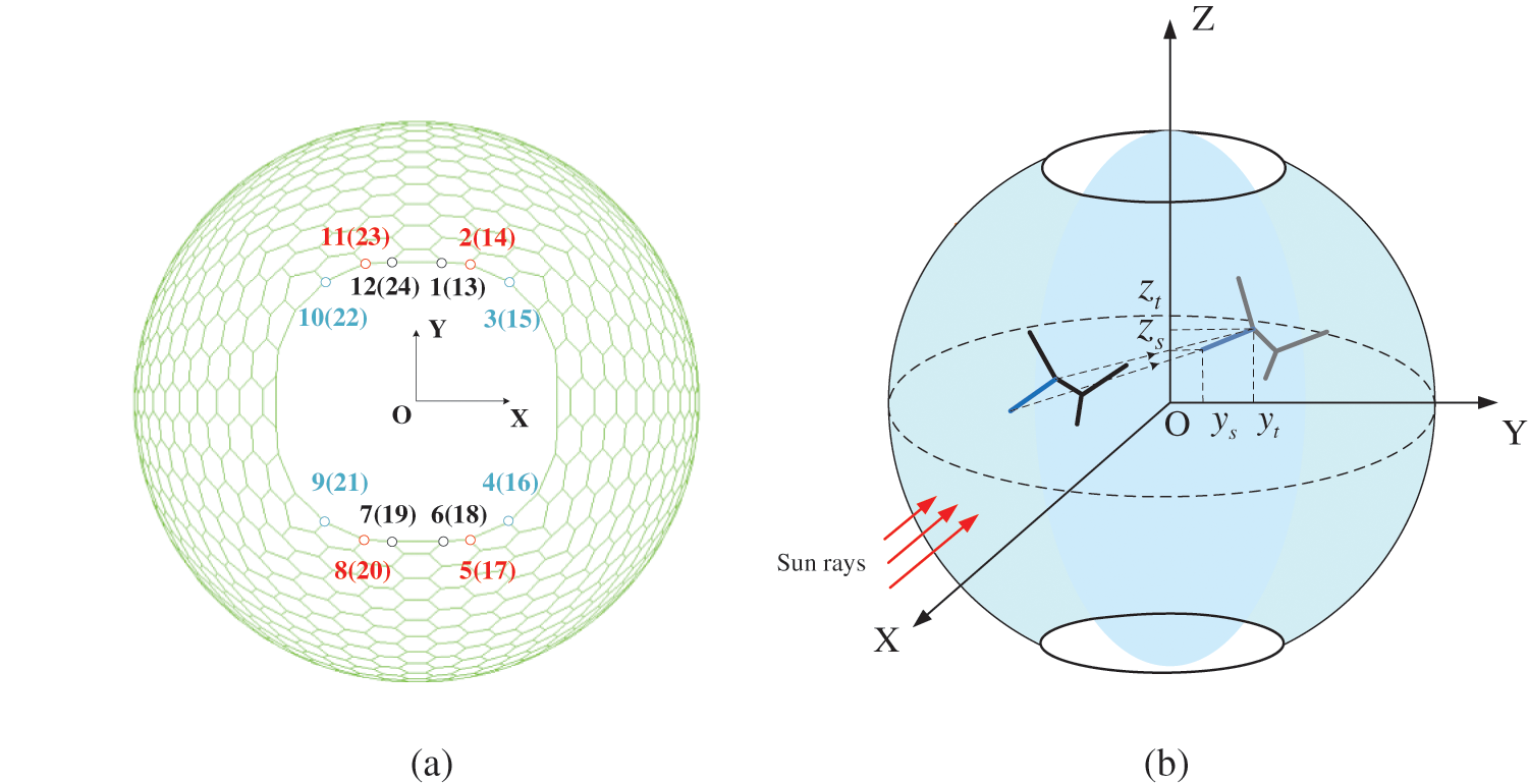
Figure 3: Illustration connection position of steel cables and the blocking of circular beams: (a) connection positions of cables; (b) blocking of circular beams
Nevertheless, the pipe beams can block the incident sun rays. As presented in Fig. 3b, the blocking area can be described by calculating the projected area of the circular beams on its aperture surface, or the O-YZ plane. The blocking area, Ab, is defined as:
where Re,i is the external radius of a circular beam, (ys,i, zs,i) and (yt,i, zt,i) are the coordinates of its start point and end point in aperture surface.
The cross-sectional area of the irradiating surface, Ar, can be calculated as:
With Eqs. (6) and (7), the blocking rate, ηs, can be calculated with:
Assuming that the beams have the same outer radius and considering that if the blocking rate cannot exceed 3%, the maximum outer radius of the beams for the 2GW-output OMEGA should not be over 0.692 m. According to the technology development planning route of the SSPS, the sunlight concentrator is about 1,500 t [22]. Therefore, the initial outer radius and inner radius are set to 0.692 and 0.687 m, respectively. The initial system mass is 1,682 t. Furthermore, the thickness of the thin-film reflectors is in um order. Relative to the size of the concentrator system, thin-film mirrors are large flexible components. In order to avoid falling into a local mode, the thin-film reflector elements are omitted in modal analysis. The static analysis and modal analysis with different connection positions are conducted, the results of which are indicated in Table 3. In Table 3, the RMS (Root Mean Square) can be expressed as:
where n is the number of nodes of the finite element model. ΔX, ΔY and ΔZ are the displacement along X, Y, and Z direction, respectively.

The structural deformation would make an influence on the solar energy collection efficiency. According to the numerical results in Table 3, the natural frequency is the same for the three cases. However, Case III has better performance on the structural deformation to Cases I and II, which would contribute to the optical and structural properties of the spherical concentrator. Therefore, Case III is studied in the following sections of this paper.
4 Optimization Model and Particle Swarm Optimization
4.1 Problem Specification and Optimization Mode
As mentioned, light collection efficiency, system quality, surface accuracy, and fundamental frequency are the key characteristic parameters of a super large-scale light collection system. The size of the GW level concentrator will reach km level, and the system will have a large mass and low dynamic stiffness. As a supporting structure, the structural characteristics of the concentrator framework directly affect the overall performance of the system. The topological connection form of the supporting structure has been obtained in the previous work in this paper, and the mesh density can be controlled by adjusting the number of segments in the longitudinal and latitudinal direction directions. Illustrated in Fig. 4, a multi-layer model is established by classifying the supporting structures into three categories.

Figure 4: Illustration of the multi-layer construction method
The structural deformation is evaluated by RMS, which has been defined with Eq. (9). The system mass can be calculated with:
where ρj is the material density, Rj and rj are the external and internal radius of different categories of the circular beams. (xs,i, ys,i, zs,i) and (xt,i, yt,i, zt,i) are the coordinates of its start point and end point in aperture surface.
For its super large scale, the concentrator is expected to reduce system mass whilst reducing the structural deformation. Therefore, a multi-objective function is established as:
where ω1 and ω2 are weighting coefficients, and ω1 + ω2 = 1.
To prevent numerical issues, two different dimensions of the objective function are translated into a unified dimensionless as follows:
where MASSmin and MASSmax are the minimum and maximum mass, RMSmin and RMSmax are the minimum and maximum RMS.
Based on the multi-layer construction method and multi-objective function, a multi-layer and multi-objective optimization model is established and optimal design is to find the optimum internal and external diameters of the three categories of the supporting structure. The optimization model can be described as follows:
where
4.2 Particle Swarm Optimization
PSO is a population-based heuristic, which is motivated by social behaviors such as bird flocking. Knowledge is optimized by social interaction in the population, which is called a swarm. PSO has the characteristics of a simple algorithm, fewer computational resources, and high convergence speed.
The PSO algorithm starts with a randomly allocated population in the search space. Each solution within the swarm is a particle, described by a vector
where
To test the proposed optimization model, the authors utilize the PSO algorithm to obtain optimal results. Three models are compared:
1. Model I: the initial conceptual design in Section 3, which the outer radius and inner radius are 0.692 m and 0.687 m, respectively;
2. Model II: the objective function and constraints are the same as the optimization model in Eq. (13), but the pipe beams are designed with only one category;
3. Model III: the proposed optimization model in Eq. (13).
Comprehensively considering calculation time and accuracy, the generation number is 200 and the population size is 100. The inertia weight ω decreases linearly from 0.9 to 0.4. Two acceleration constants C1 and C2 are set to 2.0. During the simulation, bmin, ηsmax and mmax are set to 0.005 Hz, 5%, and 2,000 t, respectively. To take account of the system mass and RMS, the weighting coefficients ω1 and ω2 are set to 0.5.
The variation of objective function and performance properties with iterations are shown in Fig. 5. The comparison between three kinds of different models is illustrated in Table 4.

Figure 5: Variation of objective function and performance properties: (a) objective function; (b) RMS; (c) max. deformation; (d) natural frequency; (e) mass; (f) blocking rate

As is illustrated in Fig. 5 and Table 4, For Model III, after convergence of iterations, the multi-objective function is converged to 0.0204. The dimensions of three categories of pipe beams are (0.23970, 0.2450), (0.3977, 0.3998), and (0.4882, 0.5000), respectively. The RMS is controlled within 0.0296 m whilst the maximum deformation is 0.0891 m. The natural frequency, system mass, and sunlight blocking rate are 0.00561 Hz, 1,130 t, and 1.5487%, respectively.
1. Comparing the results of Model I and Model III in detail, the natural frequency of Model III is decreased from 0.00774 to 0.00561 Hz. However, the RMS and maximum deformation are decreased by 1.33% and 52.20%, respectively. The system mass is reduced by 32.82% and the blocking rate is also decreased by 48.38%.
2. Comparing the results of Model II and Model III in detail, the support skeleton constructed with three types of trusses could reduce the system quality by 6.92%, light blocking rate by 28.54%, maximum deformation by 41.50%, and RMS by 9.48%, respectively. Furthermore, the fundamental frequency is raised by 0.54%.
As is stated, Model III has better performance on both structural and optical properties than Model I and Model II. The large-scale spherical concentrator optimized with the multi-layer and multi-objective optimization model could have the characteristics of lightweight, high surface precision, and high sunlight collection efficiency.
To further evaluate the dynamic properties of Model III, model analysis is also conducted and the natural frequency and corresponding modal shape are summarized in Table 5. The mode shape diagram is also shown in Fig. 6.

Figure 6: Diagram of modal shape: (a) 1st order, (b) 4th order
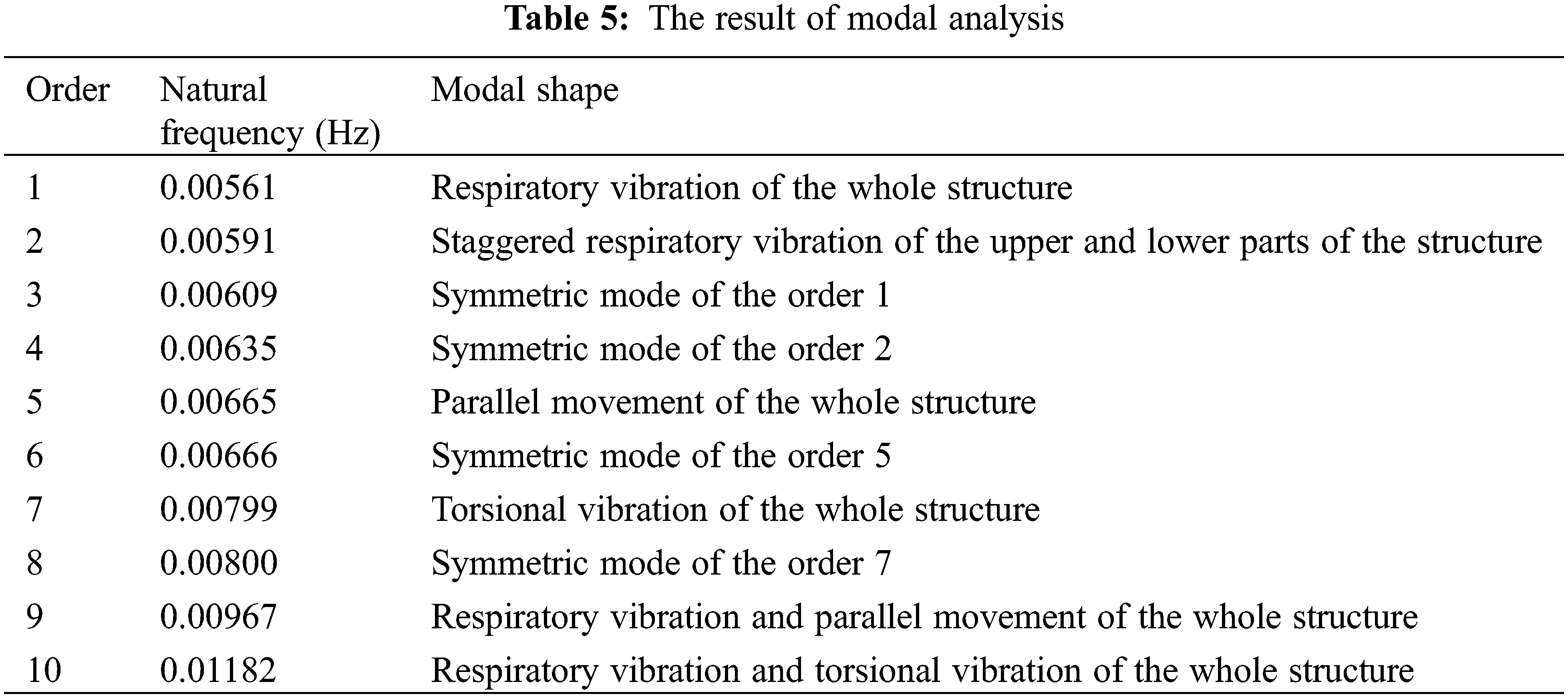
Due to the large scale of the system and the material properties at the current state, the natural frequency is low, the fundamental frequency of the supporting structure is 0.00561 Hz. From the 1st order to the 10th order, the modal shapes appear as respiratory vibration, parallel movement, and torsional vibration in different directions. In addition, there exists a corresponding symmetrical mode with different orders of torsion.
Considering the construction strategy, the regular polyhedron is utilized and mesh generation based on symmetrical sub-array was conducted in Section 2. Consequently, there exists regular torsion in the modal shape, and the symmetrical sub-arrays are useful to maintain balance and stability.
Considering the SSPS-OMEGA concept, modular design and multi-layer and multi-objective optimization design of supporting structure of large-scale spherical solar concentrator were calculated. A novel spherical grid meshed with the equatorial circles, declination circles, and meridian circles was proposed. The optical performance was also evaluated by the ray-tracing method and the collection efficiency is as high as 95%. The finite element model for the spherical concentrator was established. Structural analysis and modal analysis were performed to give a preliminary investigation of the structural static and dynamic characteristics. A multi-layer and multi-objective optimization model was proposed by a comprehensive consideration of the structural and optical properties. The numerical results by PSO have indicated better structural and optical performance such as system mass, structural deformation, natural frequency, and sunlight blocking rate. Compared to the traditional single layer, the proposed multiple layers would reduce the system mass by 6.92%, blocking rate by 28.54%, maximum deformation by 41.50%, and RMS by 9.48%, respectively. Furthermore, the fundamental frequency is also raised by 0.42%.
Although better structural and optical properties were obtained, only sunlight blocking was involved in the proposed optimization model and better sunlight collection efficiency was achieved. For further study, the sunlight efficiency loss and the variation of energy distribution on the cell array caused by the structural deformation should be evaluated. Furthermore, the thermal vibration and thermal deformation should be also considered and an optical, mechanical, electrical, thermal coupled-field simulation analysis of the SSPS would be established.
Funding Statement: The work was supported by the National Natural Science Foundation of China [No. 52105275]; the Natural Science Foundation of Shaanxi Province [2020JQ-595]; Open Fund of Shaanxi Key Laboratory of Space Solar Power Station System in Xidian University.
Conflicts of Interest: The authors declare that they have no conflicts of interest to report regarding the present study.
1. Rouge, J. D. (2007). Space-based solar power as an opportunity for strategic security: Phase 0 architecture feasibility study. Report to the Director. National Security Space Office. [Google Scholar]
2. Glaser, P. E. (1968). Power from the sun: Its future. Science, 162, 857–861. DOI 10.1126/science.162.3856.857. [Google Scholar] [CrossRef]
3. Hanley, G. M. (1980). Satellite power systems (SPS) concept definition study. NASA Contractor Report 3318. [Google Scholar]
4. Sasaki, S., Tanaka, K., Higuchi, K., Okuizumi, N., Kawasaki, S. et al. (2006). A new concept of solar power satellite: Tethered-SPS. Acta Astronautica, 60, 153–165. DOI 10.1016/j.actaastro.2006.07.010. [Google Scholar] [CrossRef]
5. Meng, X. L., Xia, X. L., Sun, C., Hou, X. B. (2014). Adjustment, error analysis and modular strategy for space solar power station. Energy Conversion and Management, 85, 292–301. DOI 10.1016/j.enconman.2014.05.070. [Google Scholar] [CrossRef]
6. Mankins, J. C. (2012). SPS-ALPHA: The first practical solar power satellite via arbitrarily large phased array. California: Artemis Innovation Management Solutions LLC. [Google Scholar]
7. Mankins, J. C. (2014). The case for space solar power. Virginia: Virginia Edition Publishing. [Google Scholar]
8. Yang, Y., Zhang, Y. Q., Duan, B. Y., Wang, D. X., Li, X. (2016). A novel design project for space solar power station (SSPS-OMEGA). Acta Astronautica, 121, 51–58. DOI 10.1016/j.actaastro.2015.12.029. [Google Scholar] [CrossRef]
9. Yang, Y., Zhang, Y. Q., Fan, G. H., Wang, D. X., Li, X. (2017). Energy distribution design on the photovoltaic cell array of the SSPS-OMEGA concept. Acta Astronautica, 134, 170–178. DOI 10.1016/j.actaastro.2017.01.034. [Google Scholar] [CrossRef]
10. Ji, X. F., Duan, B. Y., Zhang, Y. Q., Fan, G. H., Li, M. et al. (2021). Effect of operational condition of rotational subsystem on attitude control for space solar power station. Chinese Journal of Aeronautics, 34, 289–297. DOI 10.1016/j.cja.2020.12.034. [Google Scholar] [CrossRef]
11. Yang, Y., Zhang, Y. Q., Fan, G. H., Li, M., Pei, M. C. (2020). Construction strategy and performance analysis of large-scale spherical solar concentrator for the space solar power station. Solar Energy, 207, 133–143. DOI 10.1016/j.solener.2020.06.050. [Google Scholar] [CrossRef]
12. Warmann, E. C., Espinet-Gonzalez, P., Vaidya, N., Loke, S., Naqavi, A. et al. (2019). An ultralight concentrator photovoltaic system for space solar power harvesting. Acta Astronautica, 170, 443–451. DOI 10.1016/j.actaastro.2019.12.032. [Google Scholar] [CrossRef]
13. Meng, X. L., Liu, C. L., Bai, X. H., Du, K., Mallick, T. K. et al. (2019). Optical study of a cocktail structural space-based solar power station. Solar Energy, 194, 156–166. DOI 10.1016/j.solener.2019.10.053. [Google Scholar] [CrossRef]
14. Li, X., Luk, K. M. (2020). The grey wolf optimizer and its applications in electromagnetics. IEEE Transactions on Antennas and Propagation, 68, 2186–2197. DOI 10.1109/TAP.8. [Google Scholar] [CrossRef]
15. Yang, Y., Fan, G. H., Ji, X. F., Pei, M. C. (2021). Modular line-focused space solar power satellite. Aerospace, 8, 82. DOI 10.3390/aerospace8030082. [Google Scholar] [CrossRef]
16. Yang, C., Hou, X. B., Chang, S. N. (2021). A synchronous placement and size-based multi-objective optimization method for heat dissipation design on antenna module of space solar power satellite. Sustainable Energy Technologies and Assessments, 45, 101183. DOI 10.1016/j.seta.2021.101183. [Google Scholar] [CrossRef]
17. Kimerling, J. A., Sahr, K., White, D., Song, L. (1999). Comparing geometrical properties of global grids. Cartography and Geographic Information Science, 26, 271–288. DOI 10.1559/152304099782294186. [Google Scholar] [CrossRef]
18. Gray, R. W. (1995). Exact transformation equations for fuller’s world map. Cartographica: The International Journal for Geographic Information and Geovisualization, 32, 17–25. DOI 10.3138/1677-3273-Q862-1885. [Google Scholar] [CrossRef]
19. Cheng, Z. D., He, Y. L., Cui, F. Q., Xu, R. J., Tao, Y. B. (2012). Numerical simulation of a parabolic trough solar collector with nonuniform solar flux conditions by coupling FVM and MCRT method. Solar Energy, 86, 1770–1784. DOI 10.1016/j.solener.2012.02.039. [Google Scholar] [CrossRef]
20. Goswami, D. Y. (2015). Principles of solar engineering. Boca Raton, FL, USA: CRC Press. [Google Scholar]
21. Saleh Ali, I. M., O’Donovan, T. S., Reddy, K. S., Mallick, T. K. (2013). An optical analysis of a static 3-D solar concentrator. Solar Energy, 88, 57–70. DOI 10.1016/j.solener.2012.11.004. [Google Scholar] [CrossRef]
22. URSI (2007). URSI white paper on solar power satellite (SPS) systems and report of the URSI Inter-Commission Working Group on SPS. URSI Inter-Commission Working Group on SPS. [Google Scholar]
23. Selleri, S., Mussetta, M., Pirinoli, P., Zich, R. E., Matekovits, L. (2008). Differentiated meta-PSO methods for array optimization. IEEE Transactions on Antennas and Propagation, 56, 67–75. DOI 10.1109/TAP.2007.912942. [Google Scholar] [CrossRef]
24. Xu, W. Y., Zong, Y. L., Li, P., Qiu, Y. Y. (2021). Variable thickness airborne radome design considering thickness profile control and additional electromagnetic performance. IEEE Transactions on Antennas and Propagation, 69, 2443–2448. DOI 10.1109/TAP.2020.3017439. [Google Scholar] [CrossRef]
 | This work is licensed under a Creative Commons Attribution 4.0 International License, which permits unrestricted use, distribution, and reproduction in any medium, provided the original work is properly cited. |