| Journal of Renewable Materials |
DOI: 10.32604/jrm.2022.022344
ARTICLE
Experimental Evaluation of Flexural Behavior of Stress Laminated Timber Decks
1JSTI Group, Nanjing, 210017, China
2Nanjing Tech University, Nanjing, 211816, China
*Corresponding Author: Huifeng Yang. Email: hfyang@njtech.edu.cn
Received: 05 March 2022; Accepted: 20 April 2022
Abstract: Stress laminated timber (SLT) deck is assembled using timber (lumber or glulam) components placed side by side and stressed together, which has the advantages of easy prefabrication and good cost performance. This work presented an experimental investigation of bending tests performed on SLT slabs. Several parameters, including pre-stress levels, distance of pre-stressing bars, and the existence of self-tapping screw (STS) reinforcement, were taken into consideration. To reinforce the compressive property of timber perpendicular to the grain, the STSs were placed under the anchor plate of the pre-stressed bars. The experimental results were analyzed and discussed in terms of failure modes, ultimate bearing capacity, ultimate strain, and bending stiffness. It was found that the SLT slab showed satisfactory composite action as well as residual bearing capacity. The pre-stress levels showed an obvious effect on the load bearing capacity and relatively slight effect on the bending stiffness.
Keywords: Stress laminated timber; pre-stress; bridge deck slabs; self-tapping screws; bending performances
Due to its low carbon characteristics, environmental friendliness and easy installation, timber structure has been widely used in residential and commercial buildings as well as bridges. In the field of timber bridges, the deck slabs generally apply either engineered wood products (EWP) [1] or timber-concrete composite elements [2,3].
Different from other sorts of EWPs such as glued laminated timber (glulam), cross laminated timber (CLT) and laminated veneer lumber (LVL), SLT is usually more applicable for not building structures but bridges. The concept of using transverse prestressed laminated timber in bridges originated in Canada in 1970s [4]. Sarisley et al. [5] investigated the pre-stress loss of SLT bridge deck and provided a prediction model in which the creep of wood was taking into account. Ritter et al. [6] presented an overview of some methods to evaluate the field performances of SLT bridges, and detailed discussions upon the equipment and procedures for some parameter assessment were undertaken. Davalos et al. [7] conducted an analytical-experimental study of bending stiffness of the SLT decks and primarily evaluated the effect of the butt joints. Subsequently based on the existing theoretical method, the experimental results were correlated and the design recommendations were proposed. Davalos et al. [8] investigated both longitudinal/transverse bending moduli and in-plane/out-of-plane shear moduli of SLT. It was found that the longitudinal modulus of SLT can be estimated from the mean modulus of the corresponding lumber components. Crocetti et al. [9] proposed an innovative anchorage system to reduce the loss of pre-stress in SLT slab by means of STS reinforcement. Testing results showed the compression resistance of wood perpendicular to grain was considerably improved due to the application of STSs, and the creep deformation of the associated SLT deck was also reduced. Massaro et al. [10] researched the friction between the lamellas of SLT system, and found that the kinetic friction coefficient can be assumed as 0.33. Moreover, many scholars researched the influences of loading positions and butt-joint [11–13] on the flexural behaviour of the SLT deck, in which the outcomes were helpful to avoid local damages and to provide the design reference. In addition, Fortino et al. [14] reported the results of the health monitoring of SLT bridges, including an uncoated and a thick painted bridges, and the moisture content and temperature in the wood were recorded and analysed.
To achieve either larger span or wider application, some investigations have been developed on the innovative types of SLT structures. Crews [15] proposed a cellular deck composed by two SLT slabs, one above and another below, which can realize a span of 25~30 m for bridge decks. Kermani et al. [16] carried out bending and vibration tests of SLT arch bridges with the span of 20 m. Freedman et al. [17,18] also tested the SLT arch bridges with the spans ranging from 12 m to 15 m, aiming to extend the application of SLT arch bridges and reach a practical application span of 56 m. Ekevad et al. [19] focused on the slip behaviour between the glulam beam components and found that the slip will lead to the redistribution of loads sustained, and then result into a bigger load on certain beams and less load on other beams. Fleming et al. [20] developed the SLT columns constructed by low-grade timber, in which the lamination efficiency factor reached to 0.84. As a comparison, the lamination efficiency factor of the timber columns connected by self-tapping screws was 0.53.
As elaborated above, it can be found that the SLT deck showed good application potential in both pedestrian and vehicular bridges. In addition, due to its easy assembly on-site and adhesive free characteristics compared with traditional EWP, the SLT decks also have the potential cost advantage [21]. Therefore, the flexural behavior of SLT as bridge decks was evaluated. And the effects of pre-stress levels, pre-stress distance, and STS reinforcement were discussed in this paper. Experimental results were descripted in terms of failure modes, ultimate strengths, and bending stiffness.
A total of fifteen SLT slab specimens in five groups were fabricated for bending tests as shown in Table 1. The dimensions of the specimens were designed in accordance to European standard EN 408 [22] and Chinese standard GB/T 50329 [23]. The dimension of the cross-section in width × depth was 280 mm × 80 mm, and the total length of the SLT panel was 1500 mm. As shown in Table 1, the pre-stress levels, distances between prestressed bars, and STS reinforcement were considered in the bending tests.

The detailed information of specimens is shown in Figs. 1 to 3. The SLT slab consists of eight sawn timber components held together with pre-stressed steel bars. The thickness of each lumber was 35 mm, and the total width of the SLT slab was 280 mm. For the specimens in groups P300, P600 series, and P900, the uniform pre-stress of 0.3, 0.6, and 0.9 N/mm2 were applied, respectively. The pre-stress level denotes the average pressure of the outermost lumber caused by the pre-stressing. The distance between the pre-stressed bars in group P600-S300 was 300 mm, while that in other groups were 500 mm. As shown in Fig. 3, four STSs were adopted to reinforce the local compression perpendicular to lumber grain at the positions under the anchor plates. The centre distance between the STSs was 50 mm, and total length of the STS was 140 mm, which was the half of the slab width.

Figure 1: Diagrams for P300, P600, and P900 specimens (dimensions in mm)
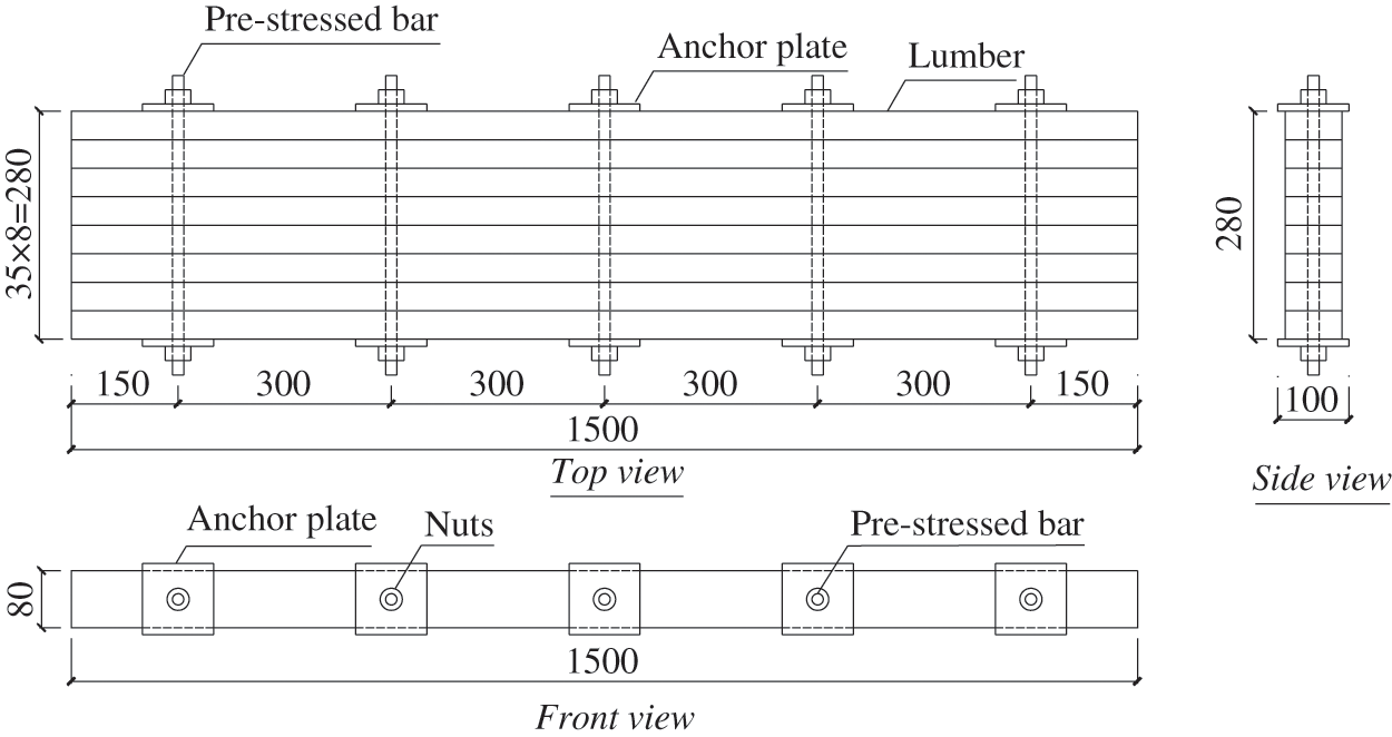
Figure 2: Diagrams for P600-S300 specimens (dimensions in mm)

Figure 3: Diagrams for P600-L140 specimens (dimensions in mm)
The timber species used was European Spruce having an average moisture content of 10.4% and average density of 555 kg/m3. The physical and mechanical properties of timber materials were tested primarily according to European standard EN 408 [22] and Chinese standard GB/T 1939 [24]. All of the average values are illustrated in Table 2.

The anchor plates were made of Q235 steel with the yield strength of 235 N/mm2. The prestressing bar was screw-thread steel bars with the yield strength of 960 N/mm2 and diameter of 14 mm. The diameter of the hole in the anchor plate was 16 mm. The sizes of the steel anchor plate were 100 mm × 100 mm × 10 mm.
The STS with the diameter of 7 mm and total length of 140 mm, designated as VGZ7140, was adopted as the local compression reinforcement. According to the manufacturer, the characteristic yield strength fy,k and withdrawal resistance strength fax,k of the STS is 1000 N/mm2 and 11.5 kN, respectively. The diameter of pre-drilled hole for STS was 4 mm.
All SLT slab specimens, with a net span of 1400 mm, were tested with the four-point bending tests in accordance with EN 408 [22] and GB/T 50329 [23], with the test setup as shown in Fig. 4. The loading rate of 3 mm/min was adopted for all specimens.
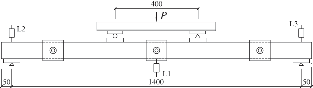
Figure 4: Test setup (dimensions in mm)
The displacements of the SLT slab at the mid-span and supports were both measured by linear voltage displacement transducers (LVDT), as shown in Fig. 4. The LVDT named as L1 was used to measure the mid-span deflection, while the LVDTs named as L2 and L3 were set to measure the displacement at both supports. The strains of the timber at the top and the bottom of the slab were measured by strain gauges, which were named as S1~S8, as shown in Fig. 5. Strain gauges S1~S4 were fixed to measure the timber strain at the top surface, while strain gauges S5~S8 were fixed to measure the timber strain at the bottom surface.

Figure 5: Layout of strain gauges on SLT specimens (dimensions in mm)
The typical failure photographs of SLT specimens are displayed in Fig. 6. Different groups of specimens showed no evident difference in failure modes. All of the specimens featured tension failure at the bottom of the lumbers. Moreover, the tension failure firstly occurred in one timber component. Then the rest timber components still worked as a whole to bear the applied load, till to the failure of the whole SLT slabs (see Fig. 6). Due to the rupture of some lumber components and the comprehensive stress state at late loading stage, timber shear failure occurred near the supports. However, timber shear failure was just considered as secondary failure.
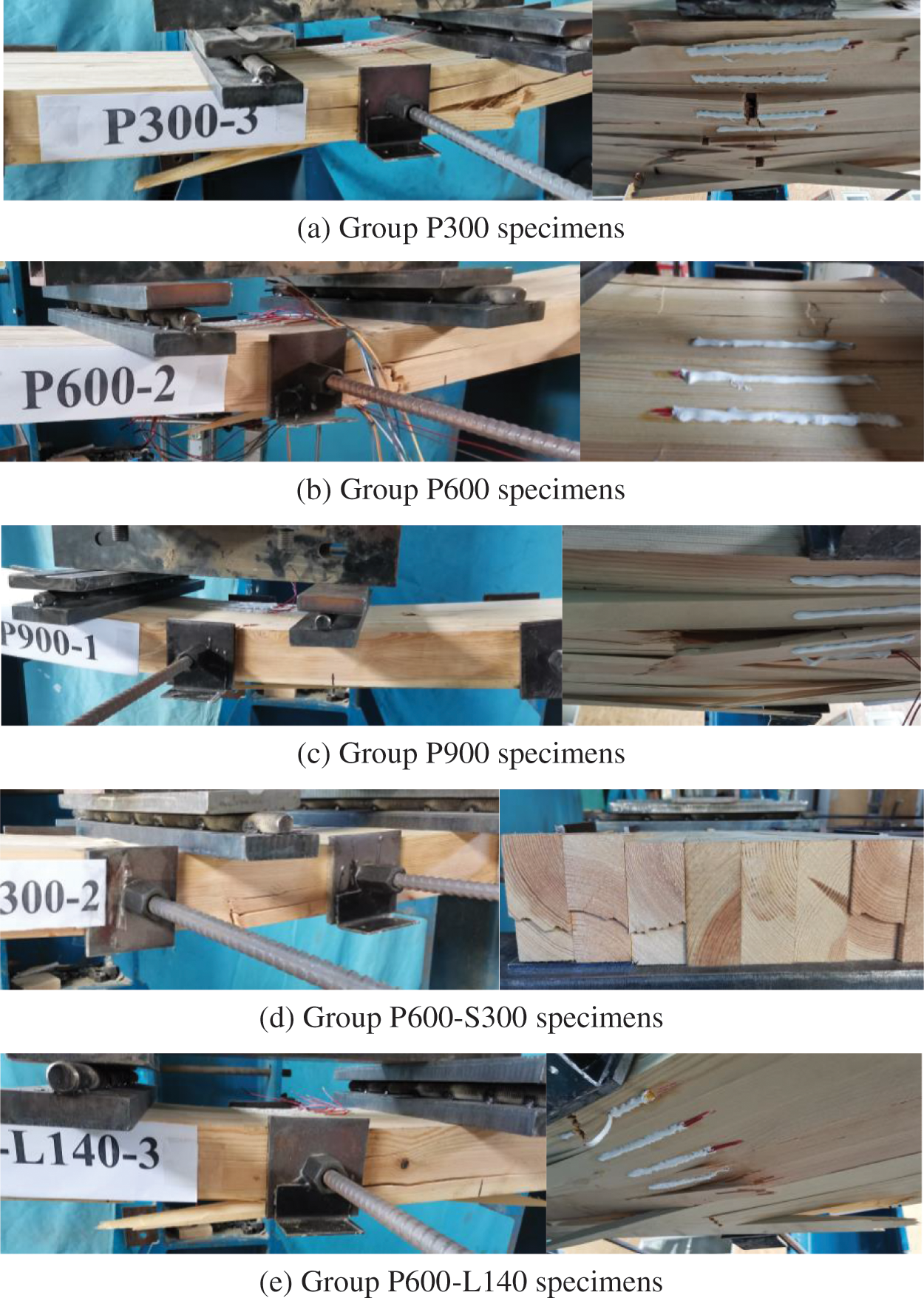
Figure 6: Failure photographs of SLT slab specimens
The load-deflection curves of the SLT slab specimens are depicted in Fig. 7. It can be seen from Fig. 7 that most specimens showed a linear elastic behaviour before the first failure of the SLT specimens occurred at the weakest timber component. After the first failure and usually a subsequent drop in load, the load increased to an even higher level. And this phenomenon may repeat one or more times, as shown in Fig. 7. It indicates that the specimen failed gradually in the last load stage and thus the specimens had a high residual strength. This was primarily due to the composite action providing by the pre-stress bars.

Figure 7: Load-deflection curves of SLT specimens
Table 3 displays some values of the test results for the specimens. From Table 3, the primary findings are as following:
(i) The pre-stress level has an evident influence on the load carrying capacity of the SLT slab. Compared with specimens P300, the specimens P600 and P900 showed the improvement in ultimate load of 15.7% and 26.8%, respectively.
(ii) The distances between the pre-stressing bars also showed an effect on the load-carrying capacities of the SLT slabs. While the distance decreased from 500 to 300 mm, the average ultimate load of the SLT slabs improved by about 9.6%.
(iii) The self-tapping screw reinforcement has little effect on the short-term load bearing capacity and bending stiffness. However, it has been proved that it can reduce the loss of pre-stress in SLT slab and therefore obtained a better composite action during the whole service life [9].

The load-strain curves were illustrated in Fig. 8. Since the load-strain curves were similar for the specimens inside each group, only one representative specimen was selected to present the load-strain curves for each group. It could be found from Fig. 8 that the outmost compressive strains have less difference than outmost tensile ones. And the tensile strains of outer components were generally larger than those of inner ones. In addition, both the maximum tensile strains and the maximum compressive ones exceeded 4000 με after the first failure occurred.

Figure 8: Load-strain curves of SLT specimens
According to Chinese standard GB/T 50329 [23], the bending stiffness can be calculated by Eq. (1), and the results were listed in Table 3. In the Eq. (1), the secant stiffness at the initial stage of the load-deflection curve was adopted.
where, ΔF refers to an increment of load on the straight-line portion of the load deformation curve; Δw refers to the increment of deformation corresponding to ΔF; l0 is the net span of the SLT slab specimens; a denotes the distance from the loading point to the nearest support.
As shown in Table 3, the bending stiffness of the specimens in group P300 reached to 15.6 × 10¹⁰ N·mm2. Increasing the pre-stress level will lead to slight improvement in bending stiffness. The average bending stiffness of the specimens in group P600 and group P900 were 16.3 × 10¹⁰ N·mm2 and 16.4 × 10¹⁰ N·mm2, respectively, which increased by 4.5% and 5.1% compared with P300 specimens. The bending stiffness of the SLT slab shows no evident improvement while decreasing the distance of the pre-stressed bar and adopting the STS as reinforcement.
Davalos et al. [7] supposed that the bending stiffness of the SLT slab can be calculated by Eq. (2). Therefore the theoretical value of bending stiffness of the SLT was equal to 15.1 × 10¹⁰ N·mm2. As a conservative design proposal, the bending stiffness of the SLT slab could be determined as the bending stiffness of the ideal section.
where, k is the reduction factor considering the butt joints, and can be determined by Eq. (3); EI is the bending stiffness of the slab section.
Further investigations will focus on the pre-stress loss in the SLT decks and the flexural performances of SLT-concrete composite slabs.
The pre-stress loss in SLT systems will be greatly influenced by the creep of the wood in compression perpendicular to grain. Zheng et al. [25] found that the creep of timber in compression perpendicular to grain was much larger than that parallel to grain. Taking the post-tensioned timber beam-column joints as an example [26], the creep of wood in compression perpendicular to grain showed non-negligible contribution on the long-term deformation of the joint. Therefore, the pre-stress loss behavior in SLT systems and the measures to reduce the creep effect, such as the STS reinforcement [9,27], will be investigated in the subsequent studies.
To improve the flexural performance of SLT decks and to provide a protection for wood from vehicles and outside environmental factors, concrete slabs could be applied as the top layer, thus forming the SLT-concrete composite bridges [28]. According to the existing investigations [29–31], the notched-screw connections, which were demonstrated to possess the high slip modulus and shear resistance, showed good feasibility. As introduced into SLT-composite systems, this sort of notched-screw connection should be investigated in detail, mainly including the notch dimension, notch distance, pre-stress level as well as slab depth.
The flexural behaviours of the stress laminated timber slabs were presented in this article. The effect of some parameters, such as pre-stress levels, the distances between the pre-stressed bar, and the self-tapping screw reinforcement, were evaluated. The failure modes, ultimate load bearing capacity, and the bending stiffness were discussed. Main conclusions could be drawn as following:
(1) The stress laminated timber slabs mainly showed the tension failure of the timber components. The constraint of the pre-stressed bar lead to superior composite action and as well as residual strength for the stress laminated timber slab.
(2) The pre-stress levels had more effect on the load bearing capacity than bending stiffness of the stress laminated timber slab. As the pre-stress increased from 0.3 to 0.6 N/mm2, the ultimate load increased by 15.7%, while the bending stiffness had no obvious improvement.
(3) The application of self-tapping screw reinforcement has no obvious effect on the short-term load bearing capacity and bending stiffness. However, it can reduce the loss of pre-stress in stress laminated timber slab and therefore obtained a better composite action.
Funding Statement: This research was sponsored by the National Natural Science Foundation of China (Grant Nos. 51878344 and 51578284).
Conflicts of Interest: The authors declare that they have no conflicts of interest to report regarding the present study.
1. Buck, D., Wang, X. A., Hagman, O., Gustafsson, A. (2015). Comparison of different assembling techniques regarding cost, durability, and ecology–A survey of multi-layer wooden panel assembly load-bearing construction elements. BioResources, 10(4), 8378–8396. DOI 10.15376/biores.10.4.8378-8396. [Google Scholar] [CrossRef]
2. Rodrigues, J. N., Providência, P., Dias, A. M. (2017). Sustainability and lifecycle assessment of timber-concrete composite bridges. Journal of Infrastructure Systems, 23(1), 04016025. DOI 10.1061/(ASCE)IS.1943-555X.0000310. [Google Scholar] [CrossRef]
3. Shi, B., Liu, W., Yang, H., Ling, X. (2020). Long-term performance of timber-concrete composite systems with notch-screw connections. Engineering Structures, 213(1), 110585. DOI 10.1016/j.engstruct.2020.110585. [Google Scholar] [CrossRef]
4. Oliva, M. G., Dimakis, A. G., Ritter, M. (1987). Development and use of stress laminated timber deck bridges. Proceedings of the Sessions at Structures Congress, pp. 249–255. Orlando, FL, USA. [Google Scholar]
5. Sarisley Jr, E. F., Accorsi, M. L. (1990). Prestress level in stress-laminated timber bridges. Journal of Structural Engineering, 116(11), 3003–3019. DOI 10.1061/(ASCE)0733-9445(1990)116:11(3003). [Google Scholar] [CrossRef]
6. Ritter, M. A., Geske, E. A., McCutcheon, W. J., Moody, R. C., Wacker, J. P. et al. (1991). Methods for assessing the field performance of stress-laminated timber bridges. Proceedings of the 1991 International Conference on Timber Engineering, pp. 319–326. Londres, Inglaterra. [Google Scholar]
7. Davalos, J. F., Kish, D. A., Wolcott, M. P. (1993). Bending stiffness of stress-laminated timber decks with butt joints. Journal of Structural Engineering, 119(5), 1670–1676. DOI 10.1061/(ASCE)0733-9445(1993)119:5(1670). [Google Scholar] [CrossRef]
8. Davalos, J. F., Sonti, S. S., Shaik, S., Moody, R. C., Hernandez, R. (1996). System stiffness for stress-laminated timber bridge decks. International Wood Engineering Conference, pp. 213–220. New Orleans, LA, USA. [Google Scholar]
9. Crocetti, R., Ekholm, K., Kliger, R. (2016). Stress-laminated-timber decks: State of the art and design based on Swedish practice. European Journal of Wood and Wood Products, 74(3), 453–461. DOI 10.1007/s00107-015-0966-1. [Google Scholar] [CrossRef]
10. Massaro, F. M., Malo, K. A. (2020). Stress-laminated timber decks in bridges: Friction between lamellas, butt joints and pre-stressing system. Engineering Structures, 213, 110592. DOI 10.1016/j.engstruct.2020.110592. [Google Scholar] [CrossRef]
11. Ekholm, K., Kliger, R., Crocetti, R. (2012). Full-scale ultimate-load test of a stress-laminated-timber bridge deck. Journal of Bridge Engineering, 17(4), 691–699. DOI 10.1061/(ASCE)BE.1943-5592.0000304. [Google Scholar] [CrossRef]
12. Ekholm, K., Kliger, I. R. (2014). Effect of vertical interlaminar shear slip and butt joints in narrow stress-laminated-timber bridge decks. Engineering Structures, 72, 161–170. DOI 10.1016/j.engstruct.2014.03.023. [Google Scholar] [CrossRef]
13. Lima do Nascimento, M., Castanheira Rodrigues, E. F., Christoforo, A. L., Rocco Lahr, F. A., Gobatto Balanco, G. (2021). Structural analysis of a stress-laminated-timber bridge deck using hardwood. Journal of Bridge Engineering, 26(3), 04021005. DOI 10.1061/(ASCE)BE.1943-5592.0001658. [Google Scholar] [CrossRef]
14. Fortino, S., Hradil, P., Koski, K., Korkealaako, A., Fülöp, L. et al. (2021). Health monitoring of stress-laminated timber bridges assisted by a hygro-thermal model for wood material. Applied Sciences, 11(1), 98. DOI 10.3390/app11010098. [Google Scholar] [CrossRef]
15. Crews, K. (2003). An overview of the development of stress laminated cellular timber bridge decks for short to medium span applications in Australia. International Conference on High Performance Materials in Bridges, pp. 162–172. Kona, Hawaii, USA. [Google Scholar]
16. Kermani, A., Freedman, G. (2005). Performance of a stress-laminated-timber arch bridge. Proceedings of the Institution of Civil Engineers-Bridge Engineering, 158(4), 155–164. DOI 10.1680/bren.2005.158.4.155. [Google Scholar] [CrossRef]
17. Freedman, G., Kermani, A. (2004). Development of long span stress-laminated timber arch bridges. Proceedings 8th World Conference on Timber Engineering, vol. 2, pp. 301–306. Lahti, Finland. [Google Scholar]
18. Freedman, G., Kermani, A. (2004). Stress-laminated arches: A stronger case for timber bridges. Proceedings of the Institution of Civil Engineers-Civil Engineering, 157(4), 172–178. DOI 10.1680/cien.2004.157.4.172. [Google Scholar] [CrossRef]
19. Ekevad, M., Jacobsson, P., Forsberg, G. (2011). Slip between glue-laminated beams in stress-laminated timber bridges: Finite-element model and full-scale destructive test. Journal of Bridge Engineering, 16(2), 188–196. DOI 10.1061/(ASCE)BE.1943-5592.0000153. [Google Scholar] [CrossRef]
20. Fleming, P. H., Ramage, M. H. (2020). Full-scale construction and testing of stress-laminated columns made with low-grade wood. Construction and Building Materials, 230, 116952. DOI 10.1016/j.conbuildmat.2019.116952. [Google Scholar] [CrossRef]
21. Liu, W., Yang, H. (2019). Research progress on modern timber structures. Journal of Building Structures, 40(2), 16–43 (in Chinese). DOI 10.14006/j.jzjgxb.2019.02.002. [Google Scholar] [CrossRef]
22. EN 408 (2010). Timber structures—Structural timber and glued laminated timber—Determination of some physical and mechanical properties. Belgium: European Committee for Standardization (CEN). [Google Scholar]
23. GB/T 50329 (2012). Standard for test methods of timber structures. China: Ministry of Housing and Urban-Rural Development of the People’s Republic of China (MOHURD) (in Chinese). [Google Scholar]
24. GB/T 1939 (2009). Method of testing in compression perpendicular to grain of wood. China: State General Administration of the People’s Republic of China for Quality Supervision and Inspection and Quarantine (AQSIQ) (in Chinese). [Google Scholar]
25. Zheng, X., Li, Z., He, M., Lam, F. (2021). Experimental investigation on the rheological behavior of timber in longitudinal and transverse compression. Construction and Building Materials, 304(1), 124633. DOI 10.1016/j.conbuildmat.2021.124633. [Google Scholar] [CrossRef]
26. Li, Z., Zheng, X., He, M., Sun, Y., He, G. (2020). Experimental and analytical investigations into the time-dependent performance in post-tensioned timber beam-column joints under sustained loads and varied environment. Construction and Building Materials, 251(S1), 118943. DOI 10.1016/j.conbuildmat.2020.118943. [Google Scholar] [CrossRef]
27. Tang, L., Xu, W., Yang, H., Tan, G., Chen, Y. (2021). Compression strength perpendicular to the grain: Testing of glulam reinforced with self-tapping screws. Journal of Nanjing Tech University (Natural Science Edition), 43(1), 94–100 (in Chinese). DOI 10.3969/j.issn.1671-7627.2021.01.014. [Google Scholar] [CrossRef]
28. Fragiacomo, M., Gregori, A., Xue, J., Demartino, C., Toso, M. (2018). Timber-concrete composite bridges: Three case studies. Journal of Traffic and Transportation Engineering (English Edition), 5(6), 429–438. DOI 10.1016/j.jtte.2018.09.001. [Google Scholar] [CrossRef]
29. Zhang, L., Chui, C. H., Tomlinson, D. (2020). Experimental investigation on the shear properties of notched connections in mass timber panel-concrete composite floors. Construction and Building Materials, 234(10), 117375. DOI 10.1016/j.conbuildmat.2019.117375. [Google Scholar] [CrossRef]
30. Shi, B., Dai, Y., Tao, H., Yang, H. (2022). Shear performances of hybrid notch-screw connections for timber-concrete composite structures. BioResources, 17(2), 2259–2274. DOI 10.15376/biores.17.2.2259-2274. [Google Scholar] [CrossRef]
31. Tao, H., Yang, H., Zhang, J., Ju, G., Xu, J. et al. (2022). Nonlinear finite element analysis on timber-concrete composite beams. Journal of Building Engineering, 51(3), 104259. DOI 10.1016/j.jobe.2022.104259. [Google Scholar] [CrossRef]
 | This work is licensed under a Creative Commons Attribution 4.0 International License, which permits unrestricted use, distribution, and reproduction in any medium, provided the original work is properly cited. |